LEXUS LS430 2003 Factory Repair Manual
Manufacturer: LEXUS, Model Year: 2003, Model line: LS430, Model: LEXUS LS430 2003Pages: 4500, PDF Size: 87.45 MB
Page 2841 of 4500
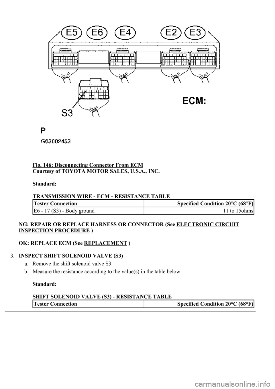
Fig. 146: Disconnecting Connector From ECM
Courtesy of TOYOTA MOTOR SALES, U.S.A., INC.
Standard:
TRANSMISSION WIRE - ECM - RESISTANCE TABLE
NG: REPAIR OR REPLACE HARNESS OR CONNECTOR (See ELECTRONIC CIRCUIT
INSPECTION PROCEDURE )
OK: REPLACE ECM (See REPLACEMENT
)
3.INSPECT SHIFT SOLENOID VALVE (S3)
a. Remove the shift solenoid valve S3.
b. Measure the resistance according to the value(s) in the table below.
Standard:
SHIFT SOLENOID VALVE (S3) - RESISTANCE TABLE
Tester ConnectionSpecified Condition 20°C (68°F)
E6 - 17 (S3) - Body ground11 to 15ohms
Tester ConnectionSpecified Condition 20°C (68°F)
Page 2842 of 4500
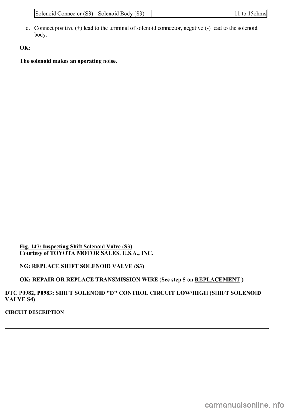
c. Connect positive (+) lead to the terminal of solenoid connector, negative (-) lead to the solenoid
body.
OK:
The solenoid makes an operating noise.
Fig. 147: Inspecting Shift Solenoid Valve (S3)
Courtesy of TOYOTA MOTOR SALES, U.S.A., INC.
NG: REPLACE SHIFT SOLENOID VALVE (S3)
OK: REPAIR OR REPLACE TRANSMISSION WIRE (See step 5 on REPLACEMENT
)
DTC P0982, P0983: SHIFT SOLENOID "D" CONTROL CIRCUIT LOW/HIGH (SHIFT SOLENOID
VALVE S4)
CIRCUIT DESCRIPTION
Solenoid Connector (S3) - Solenoid Body (S3)11 to 15ohms
Page 2843 of 4500
Shifting from 1st to 6th is performed in combination with "ON" and "OFF" operation of the shift solenoid
valves SL1, SL2, S1, S2, S3, S4 and SR which is controlled by the ECM. If an open or short circuit occurs in
either of the shift solenoid valves, the ECM controls the remaining normal shift solenoid valve to allow the
vehicle to be operated smoothly. (In case of an open or short circuit, the ECM stops sending current to the
circuit.) Fail safe function (see FAIL
-SAFE CHART ).
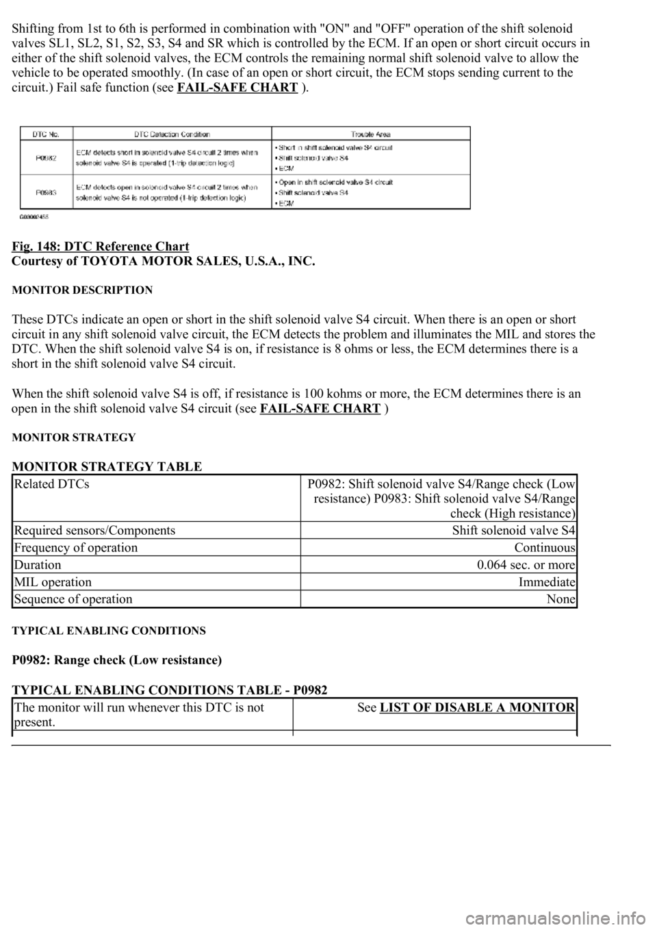
Fig. 148: DTC Reference Chart
Courtesy of TOYOTA MOTOR SALES, U.S.A., INC.
MONITOR DESCRIPTION
These DTCs indicate an open or short in the shift solenoid valve S4 circuit. When there is an open or short
circuit in any shift solenoid valve circuit, the ECM detects the problem and illuminates the MIL and stores the
DTC. When the shift solenoid valve S4 is on, if resistance is 8 ohms or less, the ECM determines there is a
short in the shift solenoid valve S4 circuit.
When the shift solenoid valve S4 is off, if resistance is 100 kohms or more, the ECM determines there is an
open in the shift solenoid valve S4 circuit (see FAIL
-SAFE CHART )
MONITOR STRATEGY
MONITOR STRATEGY TABLE
TYPICAL ENABLING CONDITIONS
P0982: Range check (Low resistance)
TYPICAL ENABLING CONDITIONS TABLE - P0982
Related DTCsP0982: Shift solenoid valve S4/Range check (Low
resistance) P0983: Shift solenoid valve S4/Range
check (High resistance)
Required sensors/ComponentsShift solenoid valve S4
Frequency of operationContinuous
Duration0.064 sec. or more
MIL operationImmediate
Sequence of operationNone
The monitor will run whenever this DTC is not
present.See LIST OF DISABLE A MONITOR
Page 2844 of 4500
P0983: Range check (High resistance)
TYPICAL ENABLING CONDITIONS TABLE - P0983
TYPICAL MALFUNCTION THRESHOLDS
P0982: Range check (Low resistance)
TYPICAL MALFUNCTION THRESHOLDS TABLE - P0982
P0983: Range check (High resistance)
TYPICAL MALFUNCTION THRESHOLDS TABLE - P0983
COMPONENT OPERATING RANGE
COMPONENT OPERATING RANGE TABLE
WIRING DIAGRAM
Shift solenoid valve S4ON
Battery voltage8 V or more
Ignition switchON
StarterOFF
The monitor will run whenever this DTC is not
present.See LIST OF DISABLE A MONITOR
Shift solenoid valve S4OFF
Battery voltage8 V or more
Ignition switchON
StarterOFF
Shift solenoid valve S4 resistance8 ohms or less
Shift solenoid valve S4 resistance100 kohms or more
Shift solenoid valve S4Resistance: 11 to 15 ohms at 20°C (68°F)
Page 2845 of 4500
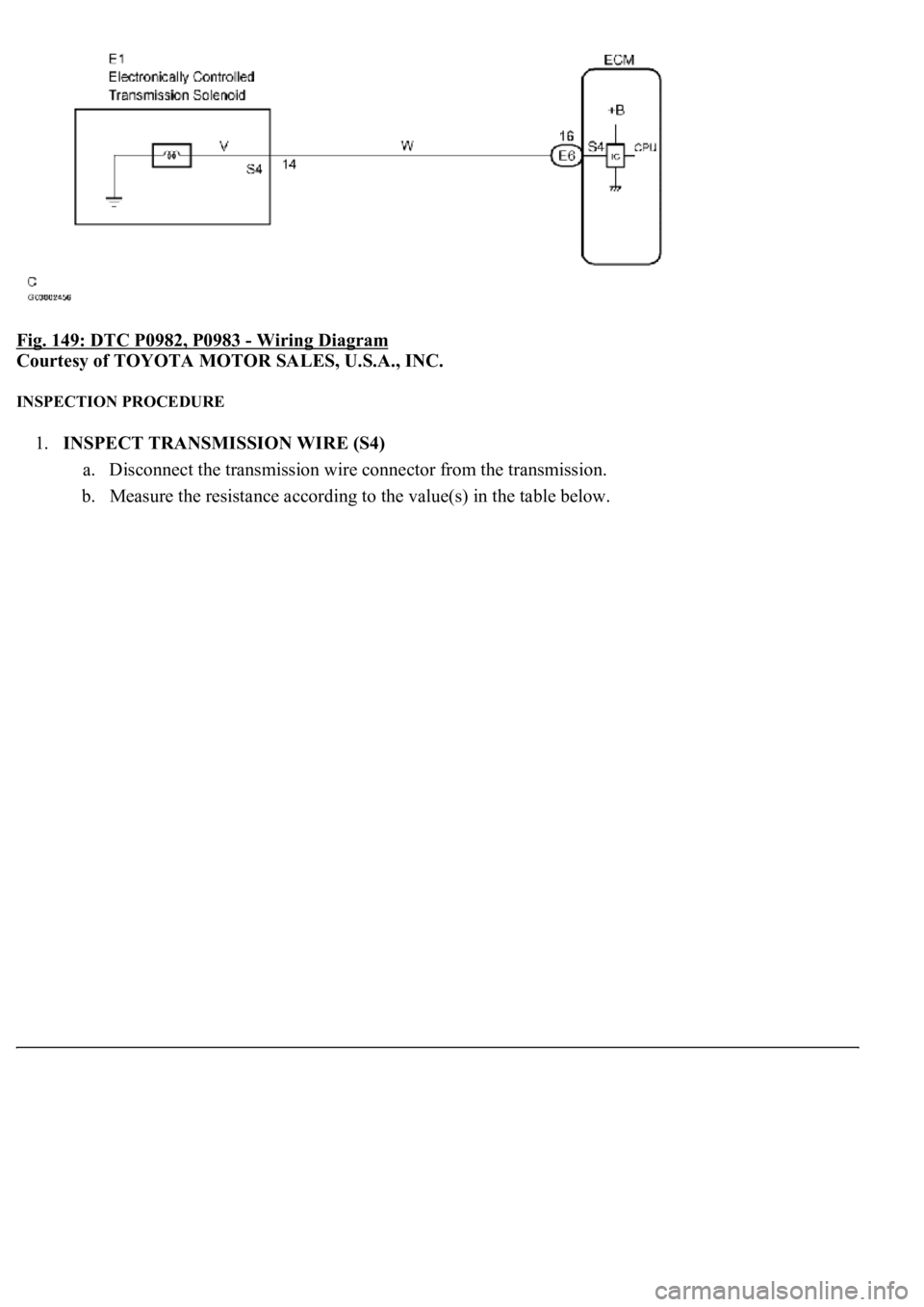
Fig. 149: DTC P0982, P0983 - Wiring Diagram
Courtesy of TOYOTA MOTOR SALES, U.S.A., INC.
INSPECTION PROCEDURE
1.INSPECT TRANSMISSION WIRE (S4)
a. Disconnect the transmission wire connector from the transmission.
b. Measure the resistance according to the value(s) in the table below.
Page 2846 of 4500
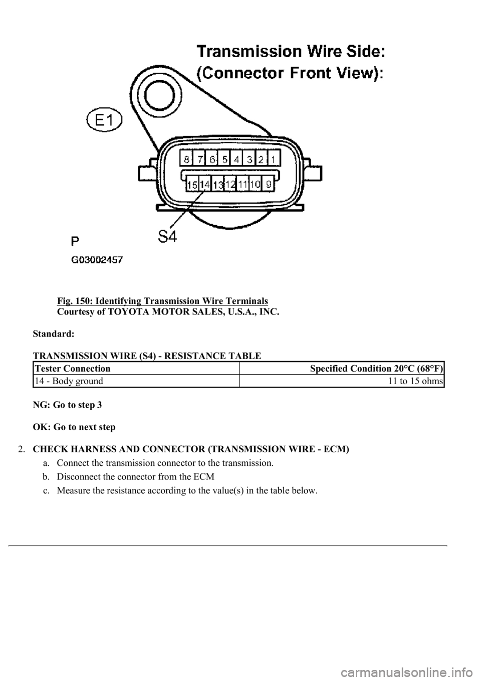
Fig. 150: Identifying Transmission Wire Terminals
Courtesy of TOYOTA MOTOR SALES, U.S.A., INC.
Standard:
TRANSMISSION WIRE (S4) - RESISTANCE TABLE
NG: Go to step 3
OK: Go to next step
2.CHECK HARNESS AND CONNECTOR (TRANSMISSION WIRE - ECM)
a. Connect the transmission connector to the transmission.
b. Disconnect the connector from the ECM
c. Measure the resistance accordin
g to the value(s) in the table below.
Tester ConnectionSpecified Condition 20°C (68°F)
14 - Body ground11 to 15 ohms
Page 2847 of 4500
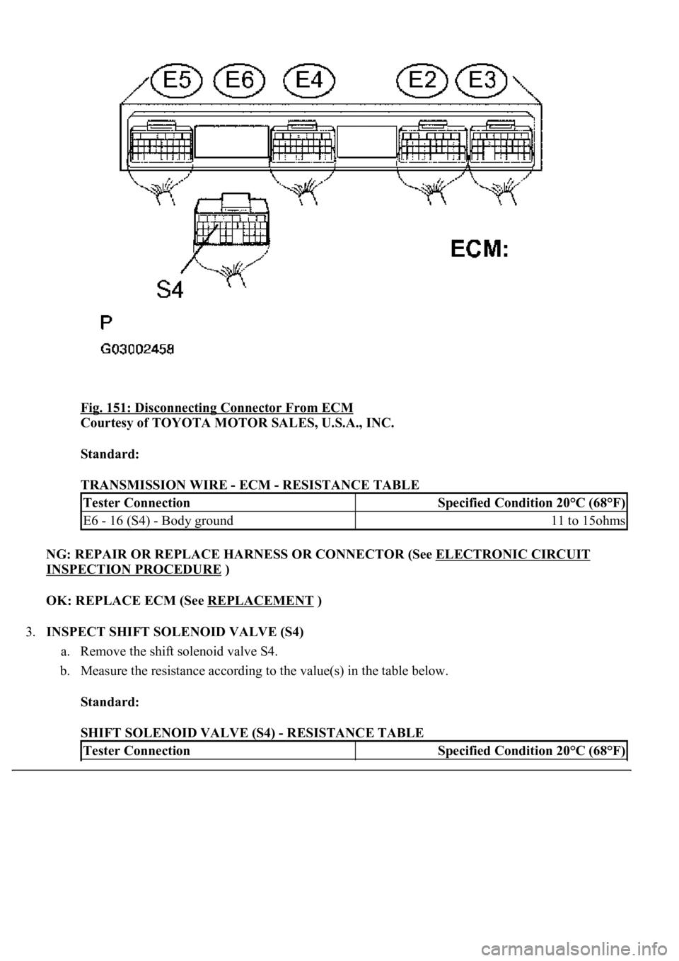
Fig. 151: Disconnecting Connector From ECM
Courtesy of TOYOTA MOTOR SALES, U.S.A., INC.
Standard:
TRANSMISSION WIRE - ECM - RESISTANCE TABLE
NG: REPAIR OR REPLACE HARNESS OR CONNECTOR (See ELECTRONIC CIRCUIT
INSPECTION PROCEDURE )
OK: REPLACE ECM (See REPLACEMENT
)
3.INSPECT SHIFT SOLENOID VALVE (S4)
a. Remove the shift solenoid valve S4.
b. Measure the resistance according to the value(s) in the table below.
Standard:
SHIFT SOLENOID VALVE (S4) - RESISTANCE TABLE
Tester ConnectionSpecified Condition 20°C (68°F)
E6 - 16 (S4) - Body ground11 to 15ohms
Tester ConnectionSpecified Condition 20°C (68°F)
Page 2848 of 4500
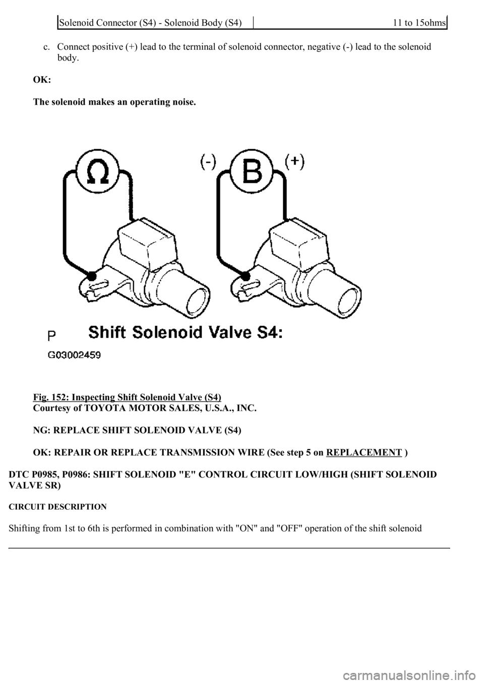
c. Connect positive (+) lead to the terminal of solenoid connector, negative (-) lead to the solenoid
body.
OK:
The solenoid makes an operating noise.
Fig. 152: Inspecting Shift Solenoid Valve (S4)
Courtesy of TOYOTA MOTOR SALES, U.S.A., INC.
NG: REPLACE SHIFT SOLENOID VALVE (S4)
OK: REPAIR OR REPLACE TRANSMISSION WIRE (See step 5 on REPLACEMENT
)
DTC P0985, P0986: SHIFT SOLENOID "E" CONTROL CIRCUIT LOW/HIGH (SHIFT SOLENOID
VALVE SR)
CIRCUIT DESCRIPTION
Shifting from 1st to 6th is performed in combination with "ON" and "OFF" operation of the shift solenoid
Solenoid Connector (S4) - Solenoid Body (S4)11 to 15ohms
Page 2849 of 4500
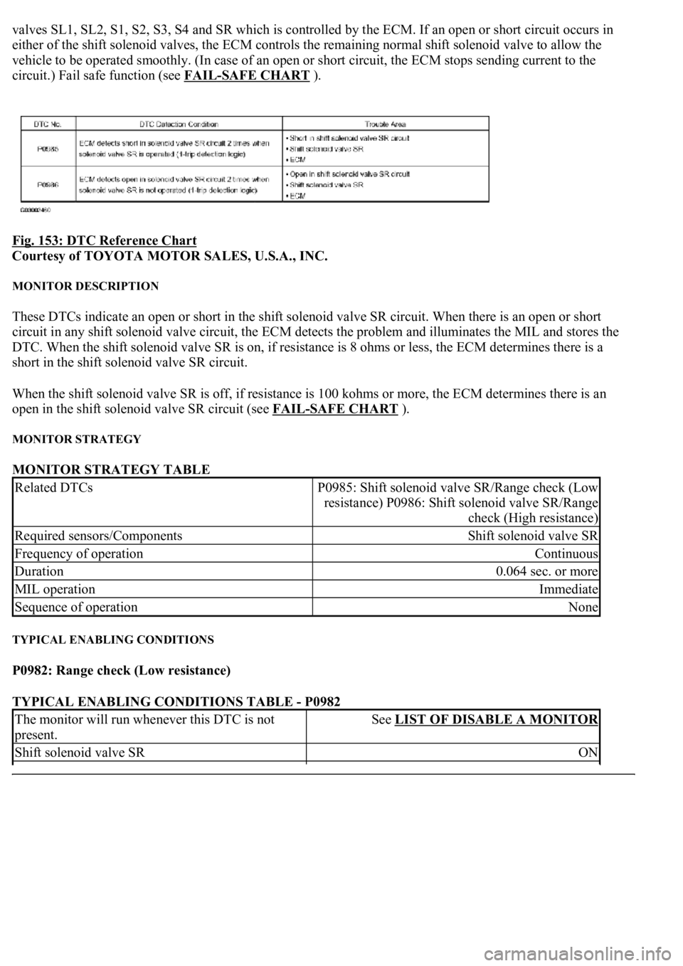
valves SL1, SL2, S1, S2, S3, S4 and SR which is controlled by the ECM. If an open or short circuit occurs in
either of the shift solenoid valves, the ECM controls the remaining normal shift solenoid valve to allow the
vehicle to be operated smoothly. (In case of an open or short circuit, the ECM stops sending current to the
circuit.) Fail safe function (see FAIL
-SAFE CHART ).
Fig. 153: DTC Reference Chart
Courtesy of TOYOTA MOTOR SALES, U.S.A., INC.
MONITOR DESCRIPTION
These DTCs indicate an open or short in the shift solenoid valve SR circuit. When there is an open or short
circuit in any shift solenoid valve circuit, the ECM detects the problem and illuminates the MIL and stores the
DTC. When the shift solenoid valve SR is on, if resistance is 8 ohms or less, the ECM determines there is a
short in the shift solenoid valve SR circuit.
When the shift solenoid valve SR is off, if resistance is 100 kohms or more, the ECM determines there is an
open in the shift solenoid valve SR circuit (see FAIL
-SAFE CHART ).
MONITOR STRATEGY
MONITOR STRATEGY TABLE
TYPICAL ENABLING CONDITIONS
P0982: Range check (Low resistance)
TYPICAL ENABLING CONDITIONS TABLE - P0982
Related DTCsP0985: Shift solenoid valve SR/Range check (Low
resistance) P0986: Shift solenoid valve SR/Range
check (High resistance)
Required sensors/ComponentsShift solenoid valve SR
Frequency of operationContinuous
Duration0.064 sec. or more
MIL operationImmediate
Sequence of operationNone
The monitor will run whenever this DTC is not
present.See LIST OF DISABLE A MONITOR
Shift solenoid valve SRON
Page 2850 of 4500
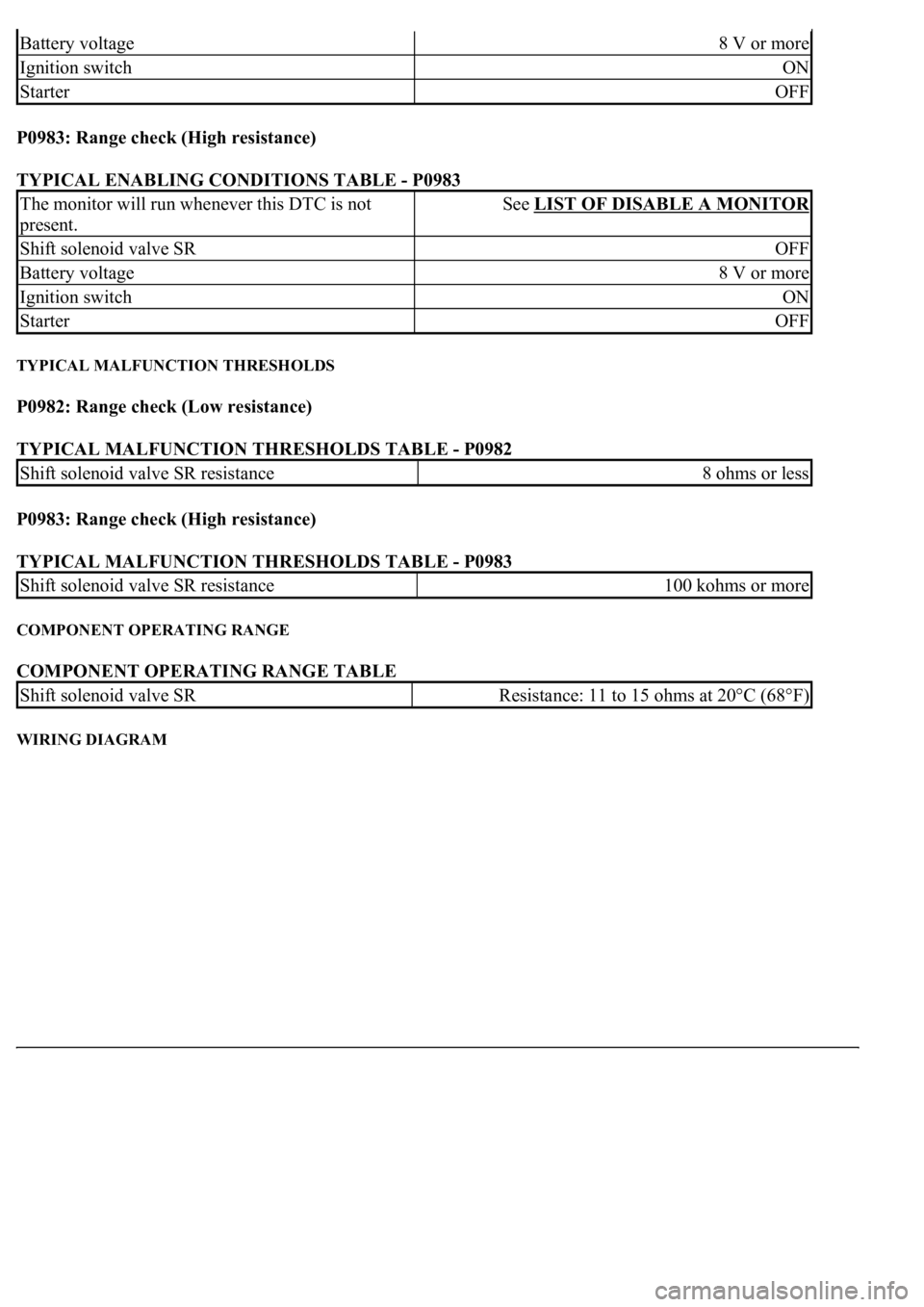
P0983: Range check (High resistance)
TYPICAL ENABLING CONDITIONS TABLE - P0983
TYPICAL MALFUNCTION THRESHOLDS
P0982: Range check (Low resistance)
TYPICAL MALFUNCTION THRESHOLDS TABLE - P0982
P0983: Range check (High resistance)
TYPICAL MALFUNCTION THRESHOLDS TABLE - P0983
COMPONENT OPERATING RANGE
COMPONENT OPERATING RANGE TABLE
WIRING DIAGRAM
Battery voltage8 V or more
Ignition switchON
StarterOFF
The monitor will run whenever this DTC is not
present.See LIST OF DISABLE A MONITOR
Shift solenoid valve SROFF
Battery voltage8 V or more
Ignition switchON
StarterOFF
Shift solenoid valve SR resistance8 ohms or less
Shift solenoid valve SR resistance100 kohms or more
Shift solenoid valve SRResistance: 11 to 15 ohms at 20°C (68°F)