LEXUS LS430 2003 Factory Repair Manual
Manufacturer: LEXUS, Model Year: 2003,
Model line: LS430,
Model: LEXUS LS430 2003
Pages: 4500, PDF Size: 87.45 MB
LEXUS LS430 2003 Factory Repair Manual
LS430 2003
LEXUS
LEXUS
https://www.carmanualsonline.info/img/36/57050/w960_57050-0.png
LEXUS LS430 2003 Factory Repair Manual
Trending: boot, radiator cap, fuel filter location, buttons, checking oil, AUX, automatic transmission
Page 2881 of 4500
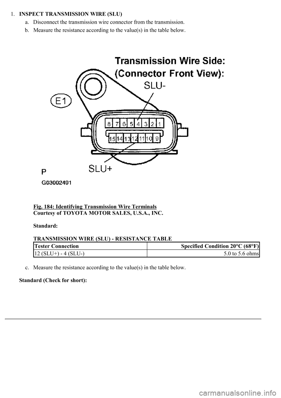
1.INSPECT TRANSMISSION WIRE (SLU)
a. Disconnect the transmission wire connector from the transmission.
b. Measure the resistance according to the value(s) in the table below.
Fig. 184: Identifying Transmission Wire Terminals
Courtesy of TOYOTA MOTOR SALES, U.S.A., INC.
Standard:
TRANSMISSION WIRE (SLU) - RESISTANCE TABLE
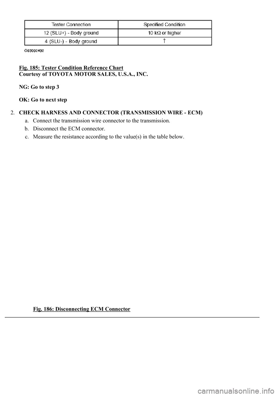
c. Measure the resistance according to the value(s) in the table below.
Standard (Check for short):
Tester ConnectionSpecified Condition 20°C (68°F)
12 (SLU+) - 4 (SLU-)5.0 to 5.6 ohms
Page 2882 of 4500
Fig. 185: Tester Condition Reference Chart
Courtesy of TOYOTA MOTOR SALES, U.S.A., INC.
NG: Go to step 3
OK: Go to next step
2.CHECK HARNESS AND CONNECTOR (TRANSMISSION WIRE - ECM)
a. Connect the transmission wire connector to the transmission.
b. Disconnect the ECM connector.
c. Measure the resistance according to the value(s) in the table below.
Fig. 186: Disconnecting ECM Connector
Page 2883 of 4500
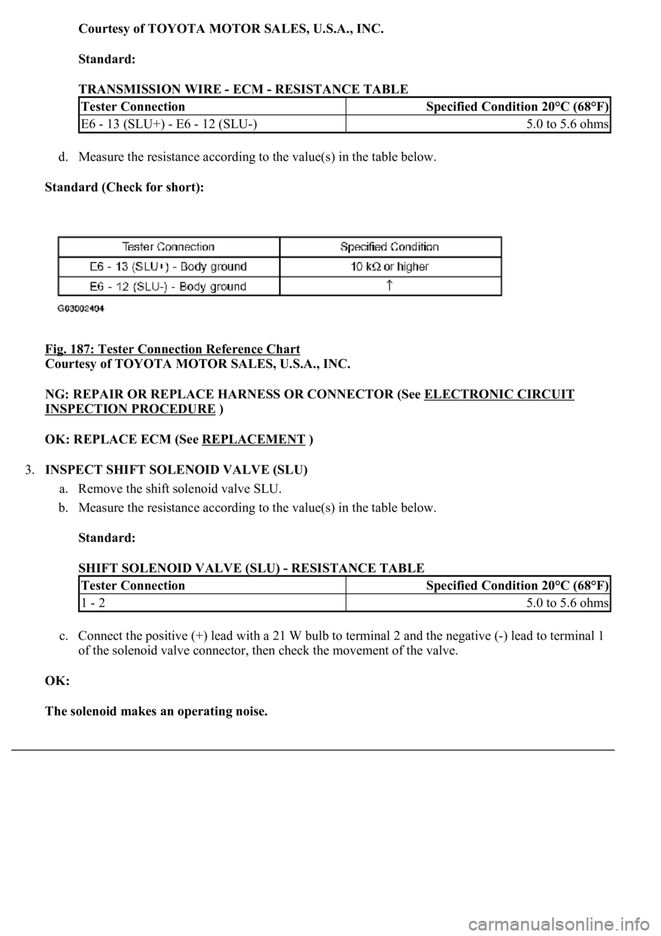
Courtesy of TOYOTA MOTOR SALES, U.S.A., INC.
Standard:
TRANSMISSION WIRE - ECM - RESISTANCE TABLE
d. Measure the resistance according to the value(s) in the table below.
Standard (Check for short):
Fig. 187: Tester Connection Reference Chart
Courtesy of TOYOTA MOTOR SALES, U.S.A., INC.
NG: REPAIR OR REPLACE HARNESS OR CONNECTOR (See ELECTRONIC CIRCUIT
INSPECTION PROCEDURE )
OK: REPLACE ECM (See REPLACEMENT
)
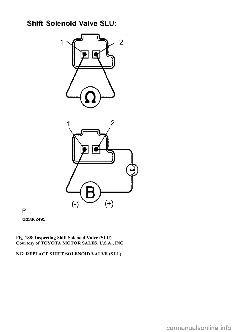
3.INSPECT SHIFT SOLENOID VALVE (SLU)
a. Remove the shift solenoid valve SLU.
b. Measure the resistance according to the value(s) in the table below.
Standard:
SHIFT SOLENOID VALVE (SLU) - RESISTANCE TABLE
c. Connect the positive (+) lead with a 21 W bulb to terminal 2 and the negative (-) lead to terminal 1
of the solenoid valve connector, then check the movement of the valve.
OK:
The solenoid makes an operating noise.
Tester ConnectionSpecified Condition 20°C (68°F)
E6 - 13 (SLU+) - E6 - 12 (SLU-)5.0 to 5.6 ohms
Tester ConnectionSpecified Condition 20°C (68°F)
1 - 25.0 to 5.6 ohms
Page 2884 of 4500
Fig. 188: Inspecting Shift Solenoid Valve (SLU)
Courtesy of TOYOTA MOTOR SALES, U.S.A., INC.
NG: REPLACE SHIFT SOLENOID VALVE (SLU)
Page 2885 of 4500
OK: REPAIR OR REPLACE TRANSMISSION WIRE (See step 5 on REPLACEMENT)
TRANSMISSION CONTROL SWITCH CIRCUIT
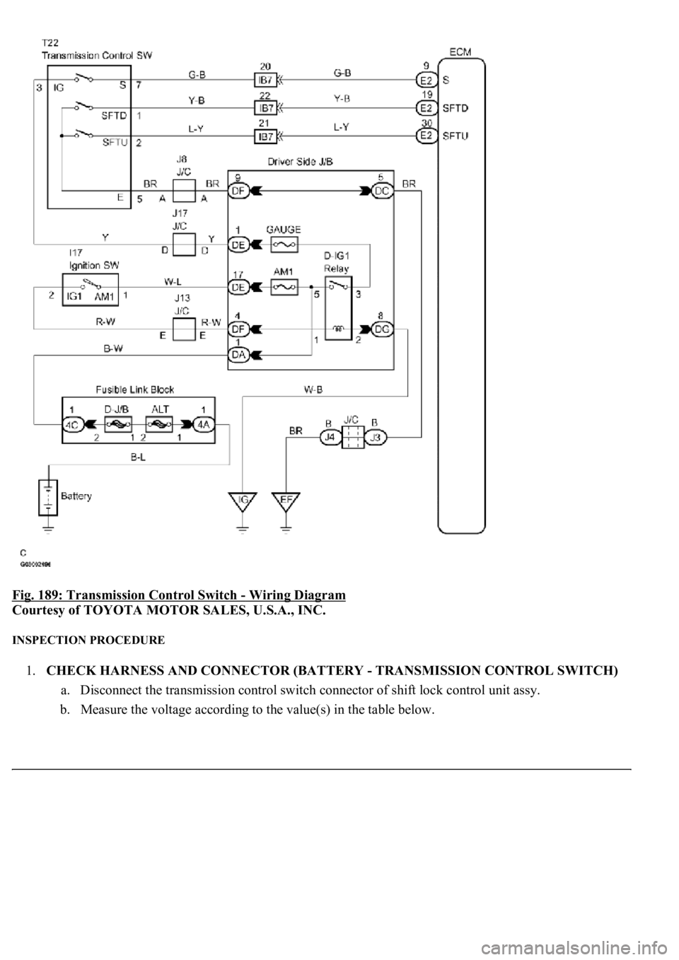
CIRCUIT DESCRIPTION
When moving the shift lever into the S position using the transmission control switch, it is possible to switch the
shift range position between "1" (first range) and "6" (sixth range).
Shifting up "+" once raises one shift range position, and shifting down "-" lowers one shift range position.
WIRING DIAGRAM
Page 2886 of 4500
Fig. 189: Transmission Control Switch - Wiring Diagram
Courtesy of TOYOTA MOTOR SALES, U.S.A., INC.
INSPECTION PROCEDURE
1.CHECK HARNESS AND CONNECTOR (BATTERY - TRANSMISSION CONTROL SWITCH)
a. Disconnect the transmission control switch connector of shift lock control unit assy.
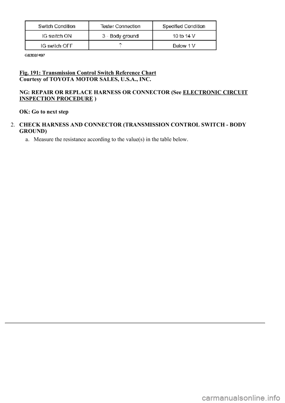
b. Measure the voltage according to the value(s) in the table below.
Page 2887 of 4500
Fig. 190: Identifying Transmission Control Switch Connector Terminals
Courtesy of TOYOTA MOTOR SALES, U.S.A., INC.
Standard:
Page 2888 of 4500
Fig. 191: Transmission Control Switch Reference Chart
Courtesy of TOYOTA MOTOR SALES, U.S.A., INC.
NG: REPAIR OR REPLACE HARNESS OR CONNECTOR (See ELECTRONIC CIRCUIT
INSPECTION PROCEDURE )
OK: Go to next step
2.CHECK HARNESS AND CONNECTOR (TRANSMISSION CONTROL SWITCH - BODY
GROUND)
a. Measure the resistance accordin
g to the value(s) in the table below.
Page 2889 of 4500
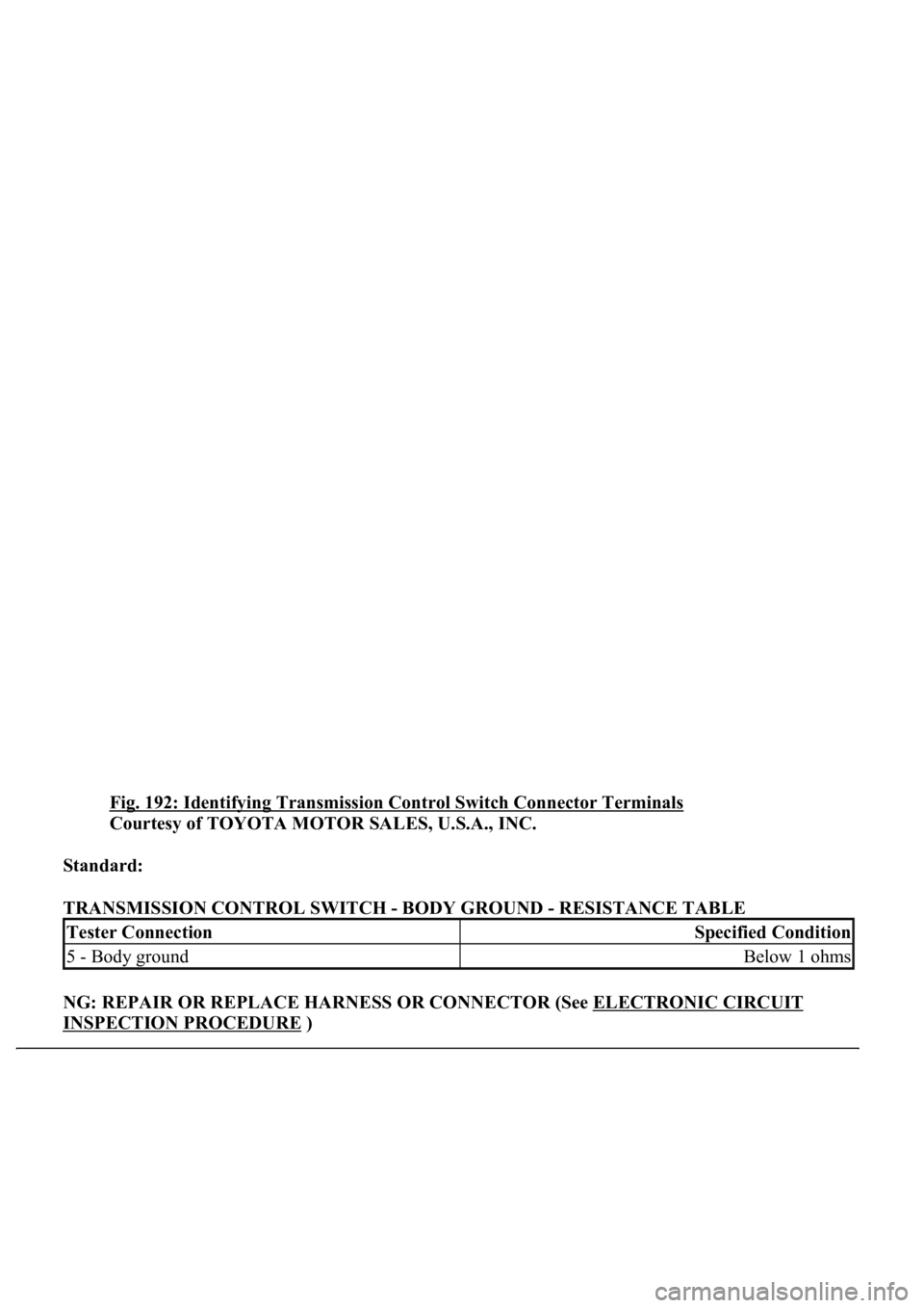
Fig. 192: Identifying Transmission Control Switch Connector Terminals
Courtesy of TOYOTA MOTOR SALES, U.S.A., INC.
Standard:
TRANSMISSION CONTROL SWITCH - BODY GROUND - RESISTANCE TABLE
NG: REPAIR OR REPLACE HARNESS OR CONNECTOR (See ELECTRONIC CIRCUIT
INSPECTION PROCEDURE )
Tester ConnectionSpecified Condition
5 - Body groundBelow 1 ohms
Page 2890 of 4500
OK: Go to next step
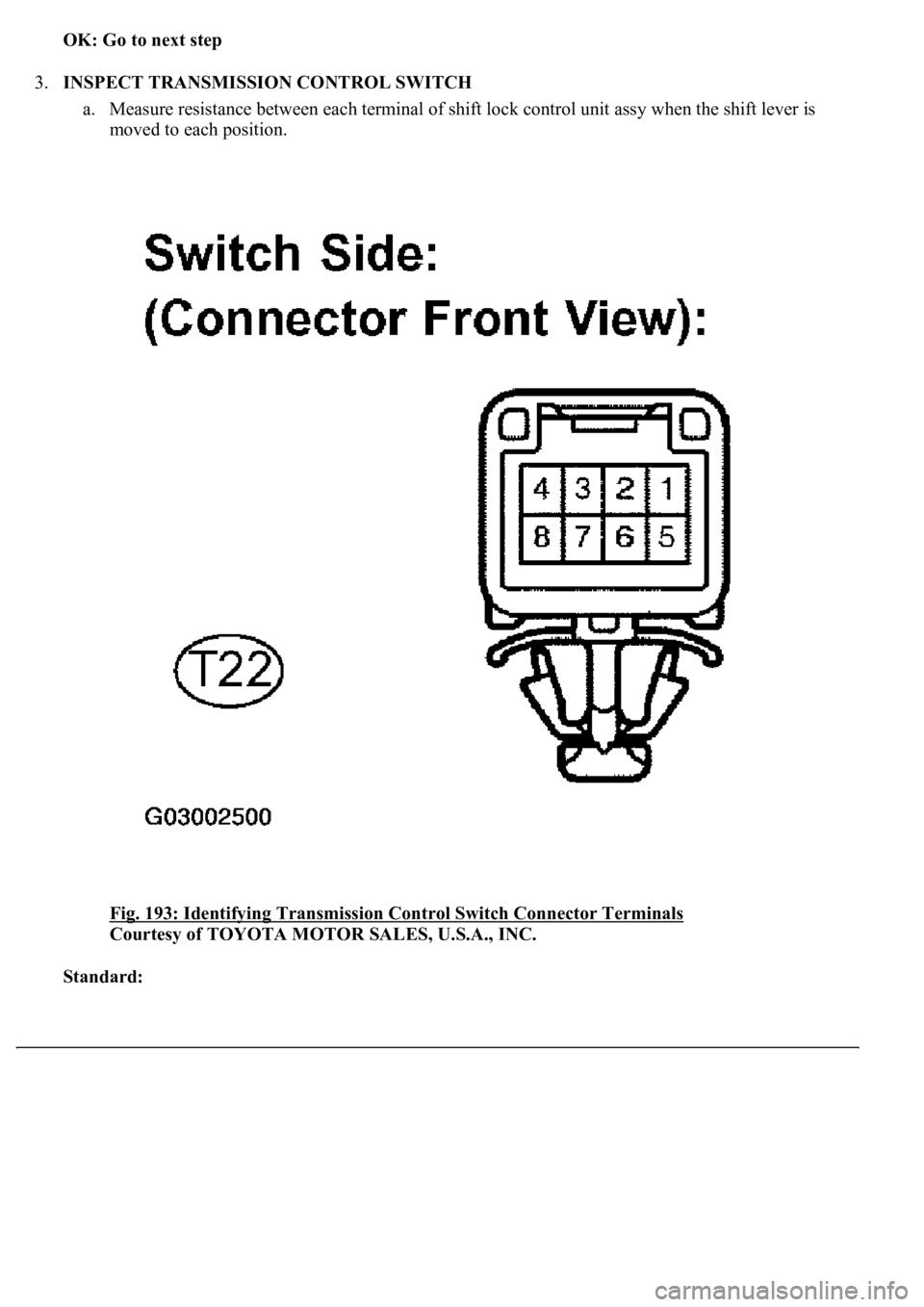
3.INSPECT TRANSMISSION CONTROL SWITCH
a. Measure resistance between each terminal of shift lock control unit assy when the shift lever is
moved to each position.
Fig. 193: Identifying Transmission Control Switch Connector Terminals
Courtesy of TOYOTA MOTOR SALES, U.S.A., INC.
Standard:
Trending: airbag off, oil, diagram, keys, engine, compressor pressure, instrument cluster
