LEXUS LS430 2003 Factory Repair Manual
Manufacturer: LEXUS, Model Year: 2003,
Model line: LS430,
Model: LEXUS LS430 2003
Pages: 4500, PDF Size: 87.45 MB
LEXUS LS430 2003 Factory Repair Manual
LS430 2003
LEXUS
LEXUS
https://www.carmanualsonline.info/img/36/57050/w960_57050-0.png
LEXUS LS430 2003 Factory Repair Manual
Trending: clutch, B2402, engine overheat, navigation, sport mode, engine coolant, change time
Page 3741 of 4500
Fig. 452: Pressing Out Bush Using SST
Courtesy of TOYOTA MOTOR SALES, U.S.A., INC.
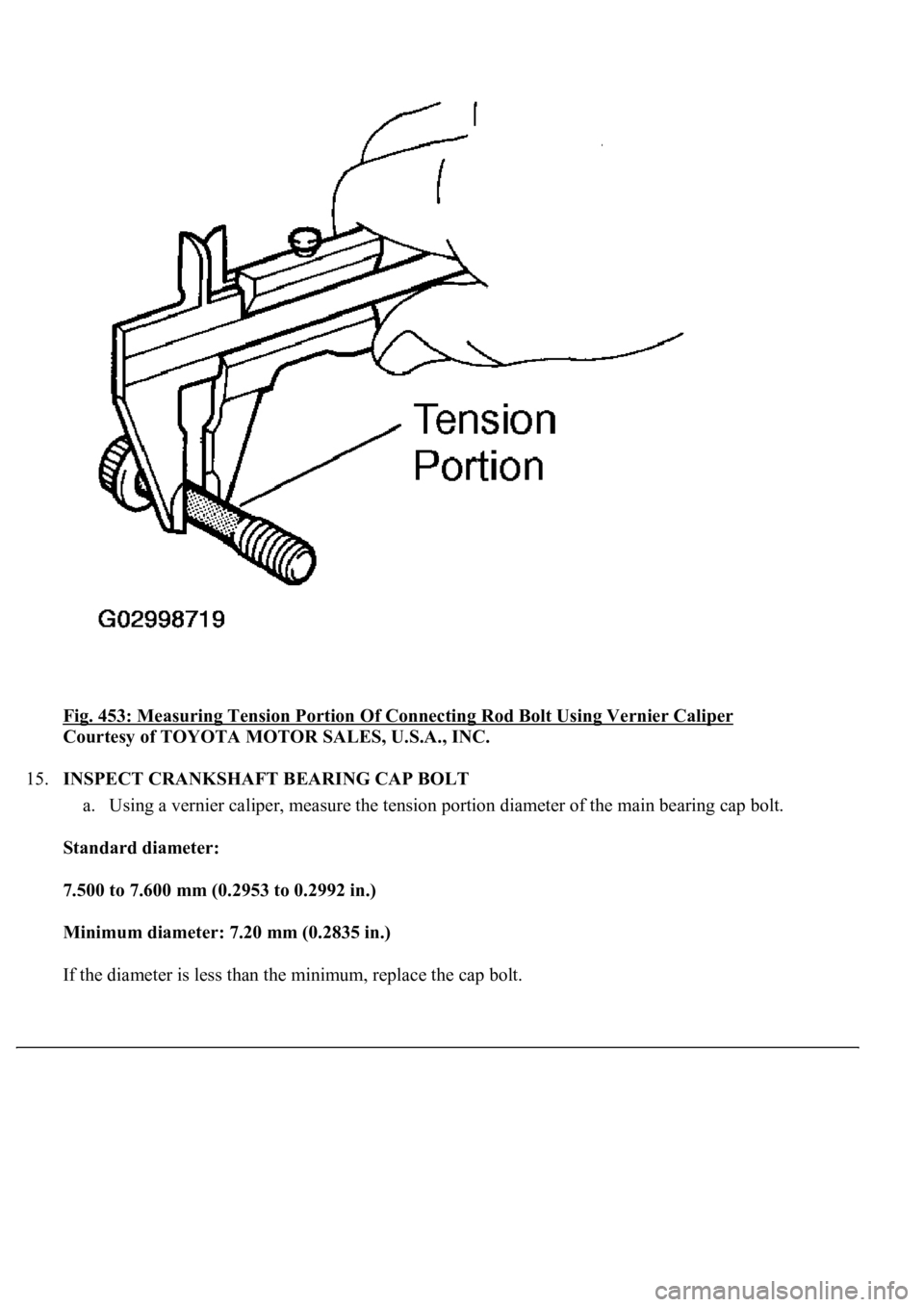
14.INSPECT CONNECTING ROD BOLT
a. Using a vernier caliper, measure the tension portion of the connecting rod bolt.
Standard diameter:
7.200 to 7.300 mm (0.2835 to 0.2874 in.)
Minimum diameter: 7.00 mm (0.2756 in.)
If the diameter is less than the minimum, replace the bolt.
Page 3742 of 4500
Fig. 453: Measuring Tension Portion Of Connecting Rod Bolt Using Vernier Caliper
Courtesy of TOYOTA MOTOR SALES, U.S.A., INC.
15.INSPECT CRANKSHAFT BEARING CAP BOLT
a. Using a vernier caliper, measure the tension portion diameter of the main bearing cap bolt.
Standard diameter:
7.500 to 7.600 mm (0.2953 to 0.2992 in.)
Minimum diameter: 7.20 mm (0.2835 in.)
If the diameter is less than the minimum, replace the cap bolt.
Page 3743 of 4500
Fig. 454: Measuring Tension Portion Diameter Of Main Bearing Cap Bolt Using Vernier Caliper
Courtesy of TOYOTA MOTOR SALES, U.S.A., INC.
16.INSPECT CRANKSHAFT
a. Inspect for circle runout.
1. Place the crankshaft on V-blocks.
2. Using a dial indicator, measure the circle runout at the center journal.
Maximum circle runout: 0.08 mm (0.0031 in.)
If the circle runout is
greater than the maximum, replace the crankshaft.
Page 3744 of 4500
Fig. 455: Measuring Circle Runout At Center Journal Using Dial Indicator
Courtesy of TOYOTA MOTOR SALES, U.S.A., INC.
b. Inspect the main journals and crank pins.
1. Using a micrometer, measure the diameter of each main journal and crank pin.
Main journal diameter:
66.988 to 67.000 mm (2.6373 to 2.6378 in.)
Crank pin diameter:
51.982 to 52.000 mm (2.0465 to 2.0472 in.)
If the diameter is not as specified, check the oil clearance (see steps 3 and 7). If necessary, replace
the crankshaft.
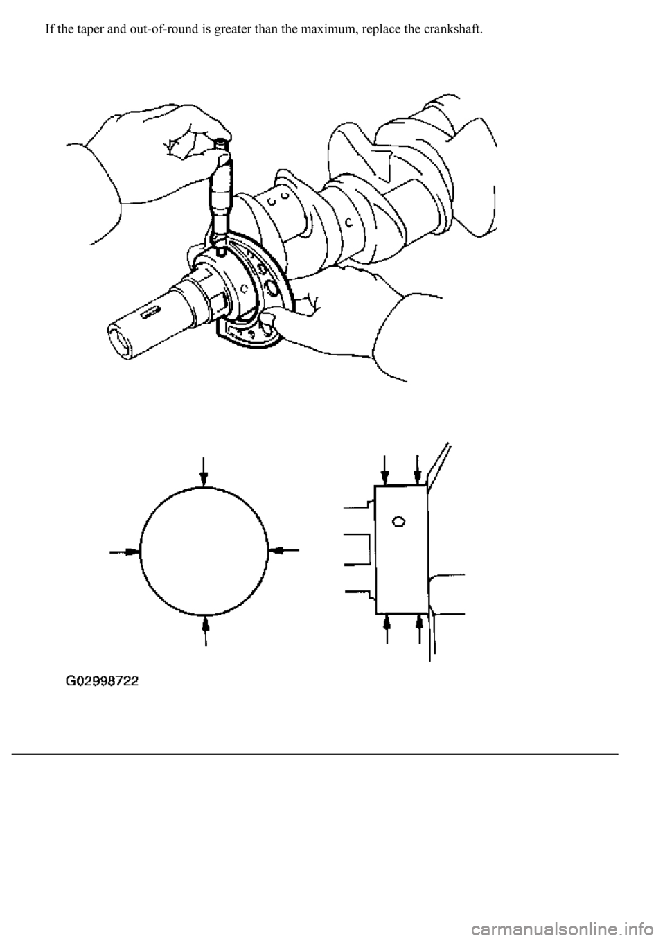
2. Check each main journal and crank pin for taper and out-of-round as shown in the illustration.
Maximum taper and out-of-round:
0.02 mm (0.0008 in.)
Page 3745 of 4500
If the taper and out-of-round is greater than the maximum, replace the crankshaft.
Page 3746 of 4500
Fig. 456: Measuring Diameter Of Each Main Journal And Crank Pin Using Micrometer
Courtesy of TOYOTA MOTOR SALES, U.S.A., INC.
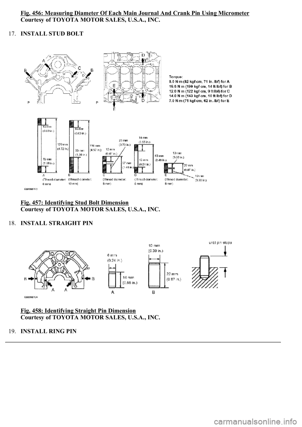
17.INSTALL STUD BOLT
Fig. 457: Identifying Stud Bolt Dimension
Courtesy of TOYOTA MOTOR SALES, U.S.A., INC.
18.INSTALL STRAIGHT PIN
Fig. 458: Identifying Straight Pin Dimension
Courtesy of TOYOTA MOTOR SALES, U.S.A., INC.
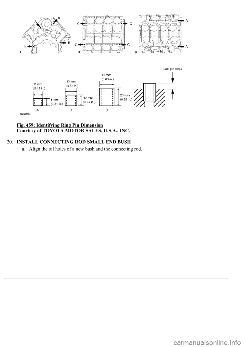
19.INSTALL RING PIN
Page 3747 of 4500
Fig. 459: Identifying Ring Pin Dimension
Courtesy of TOYOTA MOTOR SALES, U.S.A., INC.
20.INSTALL CONNECTING ROD SMALL END BUSH
a. Align the oil holes of a new bush and the connecting rod.
Page 3748 of 4500
Fig. 460: Aligning Oil Holes Of Bush And Connecting Rod
Courtesy of TOYOTA MOTOR SALES, U.S.A., INC.
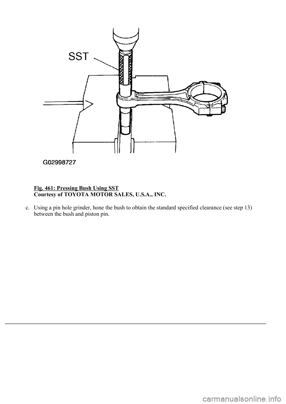
b. Using SST and a press, press in the bush.
SST 09222-30010
Page 3749 of 4500
Fig. 461: Pressing Bush Using SST
Courtesy of TOYOTA MOTOR SALES, U.S.A., INC.
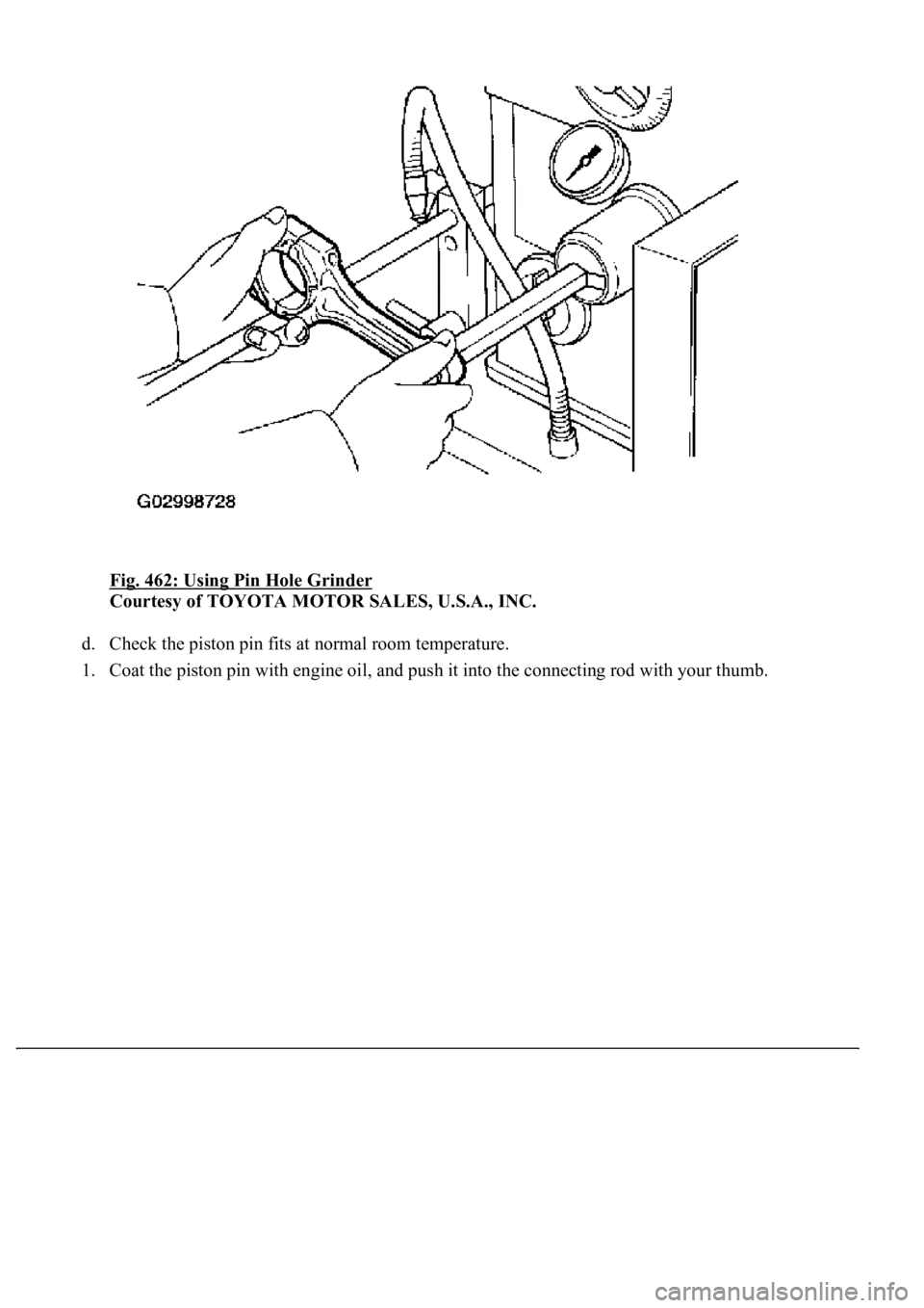
c. Using a pin hole grinder, hone the bush to obtain the standard specified clearance (see step 13)
between the bush and piston pin.
Page 3750 of 4500
Fig. 462: Using Pin Hole Grinder
Courtesy of TOYOTA MOTOR SALES, U.S.A., INC.
d. Check the piston pin fits at normal room temperature.
1. Coat the piston pin with en
gine oil, and push it into the connecting rod with your thumb.
Trending: fuel filter, airbag, brake fluid, lumbar support, rear seat back, CD player, lane assist
