LEXUS LS430 2003 Factory Repair Manual
Manufacturer: LEXUS, Model Year: 2003,
Model line: LS430,
Model: LEXUS LS430 2003
Pages: 4500, PDF Size: 87.45 MB
LEXUS LS430 2003 Factory Repair Manual
LS430 2003
LEXUS
LEXUS
https://www.carmanualsonline.info/img/36/57050/w960_57050-0.png
LEXUS LS430 2003 Factory Repair Manual
Trending: steering wheel adjustment, navigation system, cylinder head, spark plugs, cruise control, intake manifold inlet, turn signal
Page 3761 of 4500
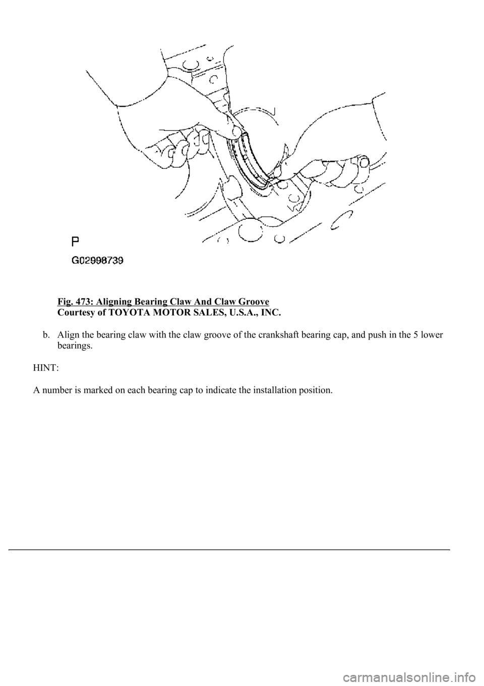
Fig. 473: Aligning Bearing Claw And Claw Groove
Courtesy of TOYOTA MOTOR SALES, U.S.A., INC.
b. Align the bearing claw with the claw groove of the crankshaft bearing cap, and push in the 5 lower
bearings.
HINT:
A number is marked on each bearin
g cap to indicate the installation position.
Page 3762 of 4500
Fig. 474: Identifying Bearing Cap Installation Position
Courtesy of TOYOTA MOTOR SALES, U.S.A., INC.
24.INSTALL CRANKSHAFT THRUST WASHER SET
a. Install the 2 thrust washers under the No. 3 journal position of the cylinder block with the oil
grooves facing outward.
Page 3763 of 4500
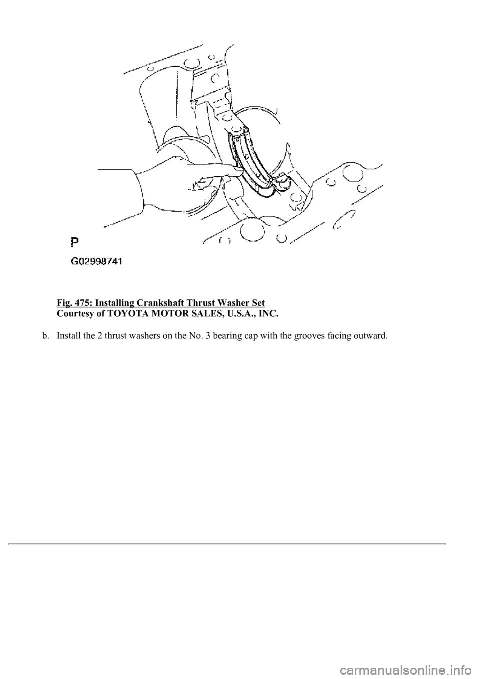
Fig. 475: Installing Crankshaft Thrust Washer Set
Courtesy of TOYOTA MOTOR SALES, U.S.A., INC.
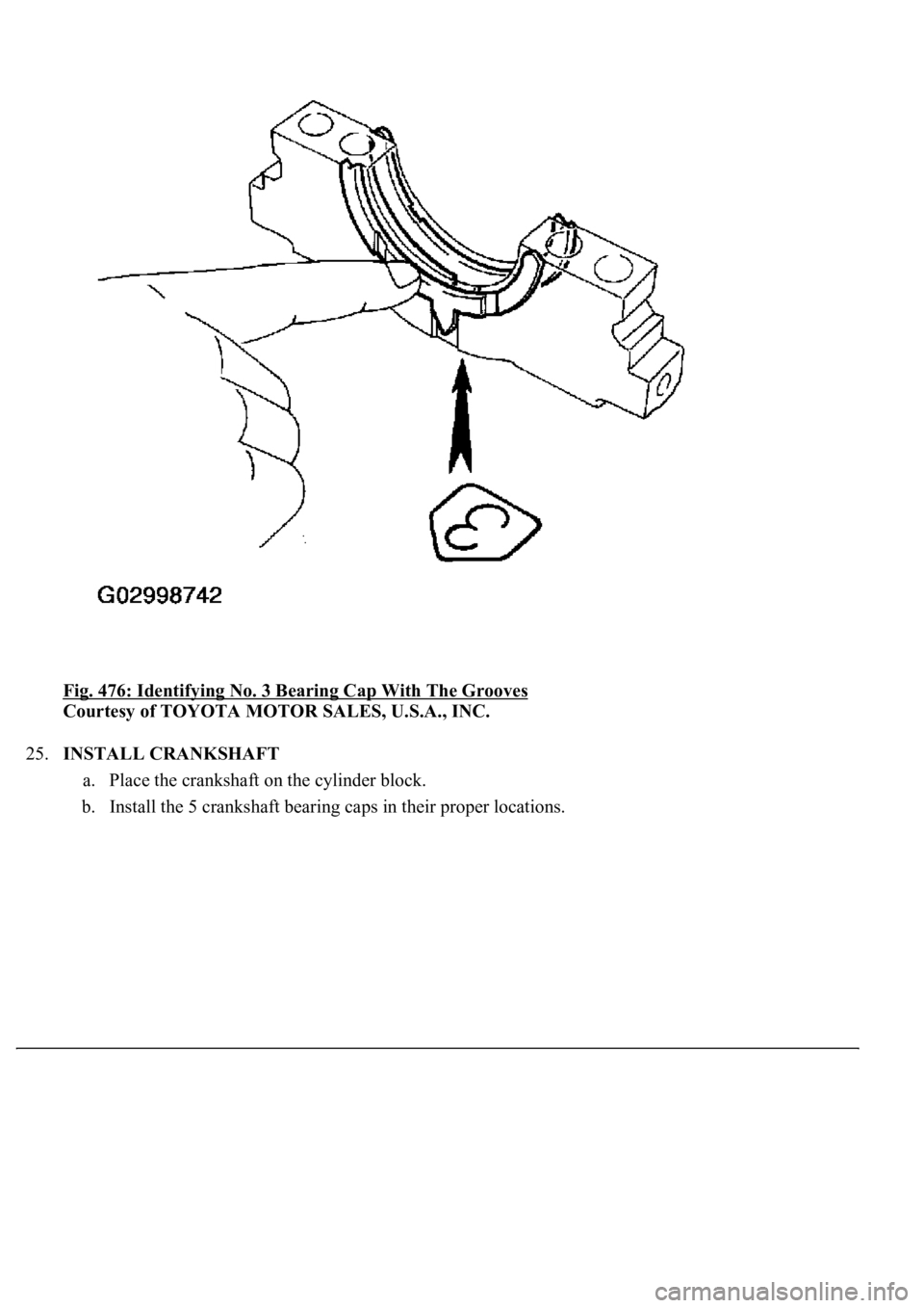
b. Install the 2 thrust washers on the No. 3 bearing cap with the grooves facing outward.
Page 3764 of 4500
Fig. 476: Identifying No. 3 Bearing Cap With The Grooves
Courtesy of TOYOTA MOTOR SALES, U.S.A., INC.
25.INSTALL CRANKSHAFT
a. Place the crankshaft on the cylinder block.
b. Install the 5 crankshaft bearing caps in their proper locations.
Page 3765 of 4500
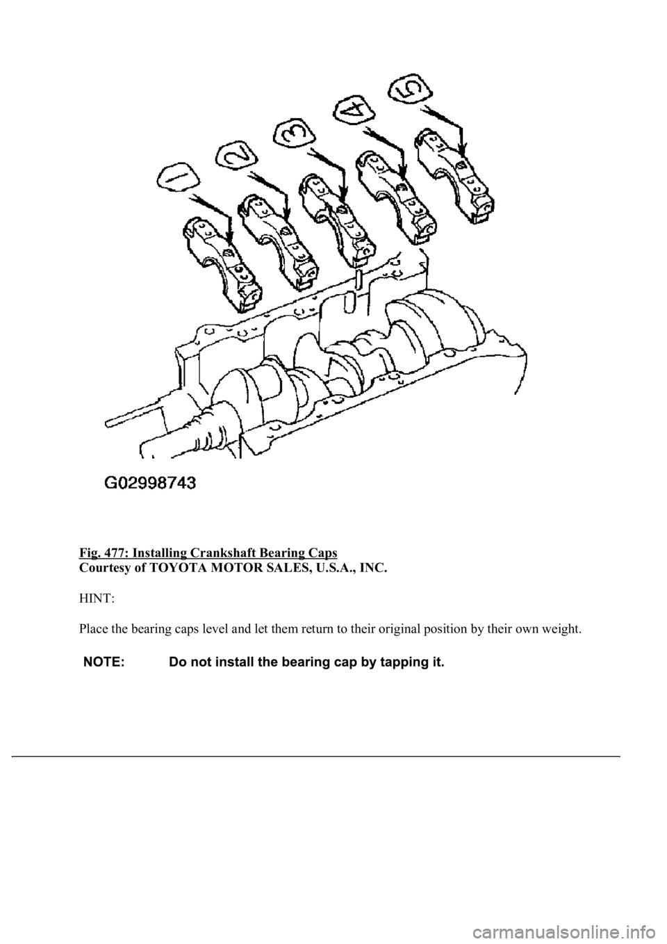
Fig. 477: Installing Crankshaft Bearing Caps
Courtesy of TOYOTA MOTOR SALES, U.S.A., INC.
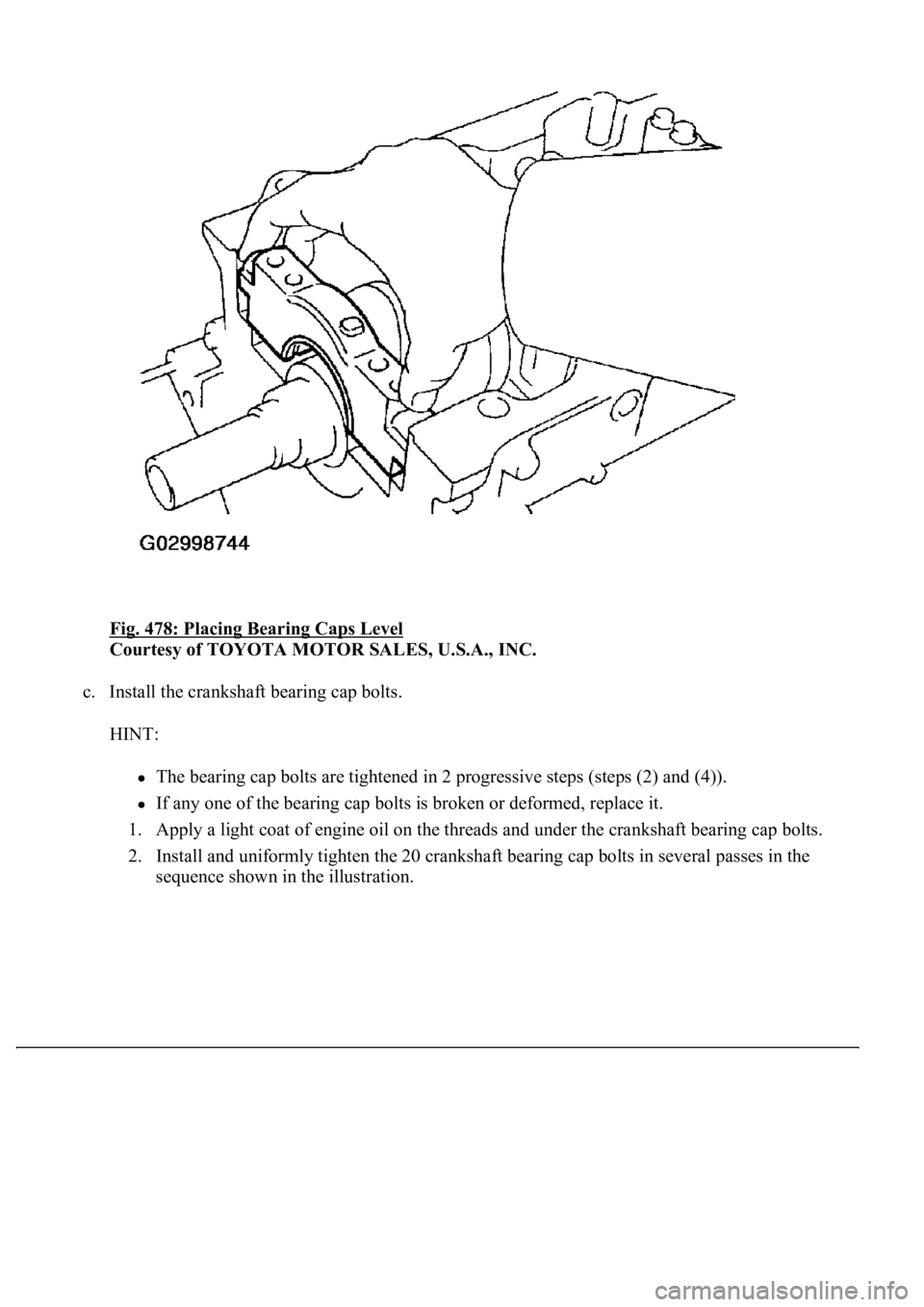
HINT:
Place the bearing caps level and let them return to their original position by their own weight.
Page 3766 of 4500
Fig. 478: Placing Bearing Caps Level
Courtesy of TOYOTA MOTOR SALES, U.S.A., INC.
c. Install the crankshaft bearing cap bolts.
HINT:
The bearing cap bolts are tightened in 2 progressive steps (steps (2) and (4)).
If any one of the bearing cap bolts is broken or deformed, replace it.
1. Apply a light coat of engine oil on the threads and under the crankshaft bearing cap bolts.
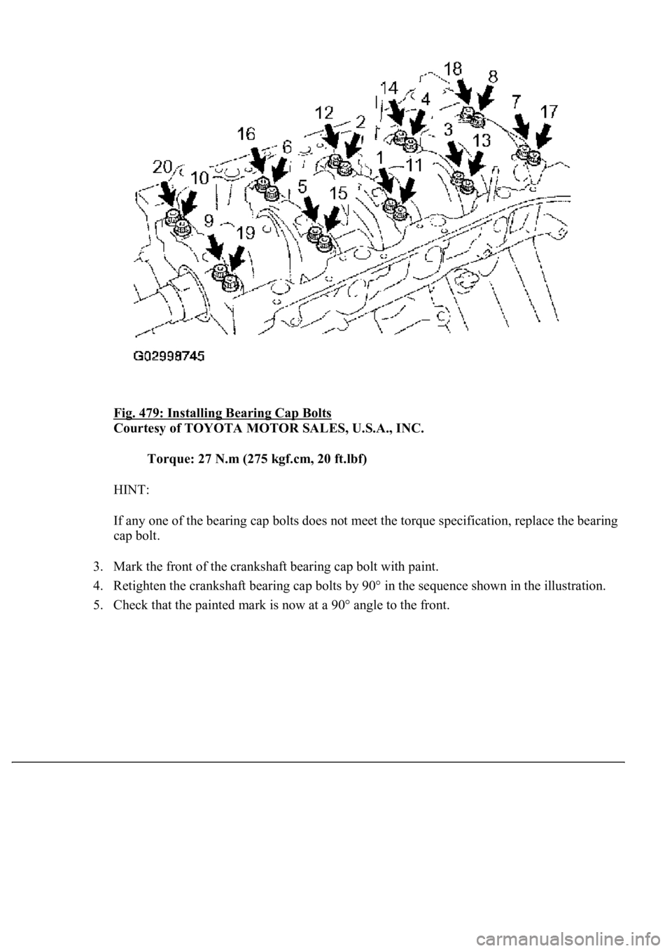
2. Install and uniformly tighten the 20 crankshaft bearing cap bolts in several passes in the
sequence shown in the illustration.
Page 3767 of 4500
Fig. 479: Installing Bearing Cap Bolts
Courtesy of TOYOTA MOTOR SALES, U.S.A., INC.
Torque: 27 N.m (275 kgf.cm, 20 ft.lbf)
HINT:
If any one of the bearing cap bolts does not meet the torque specification, replace the bearing
cap bolt.
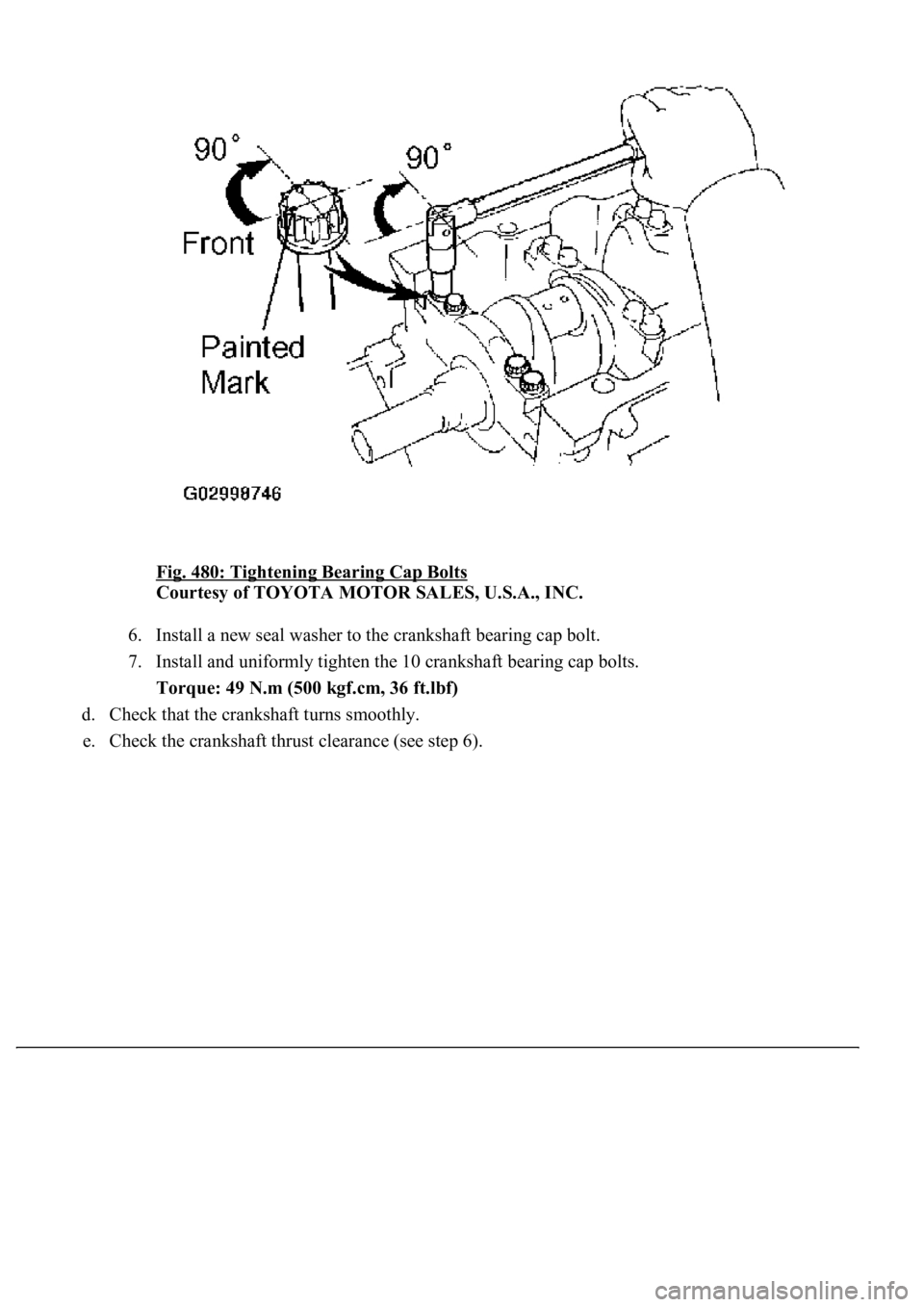
3. Mark the front of the crankshaft bearing cap bolt with paint.
4. Retighten the crankshaft bearing cap bolts by 90° in the sequence shown in the illustration.
5. Check that the painted mark is now at a 90° an
gle to the front.
Page 3768 of 4500
Fig. 480: Tightening Bearing Cap Bolts
Courtesy of TOYOTA MOTOR SALES, U.S.A., INC.
6. Install a new seal washer to the crankshaft bearing cap bolt.
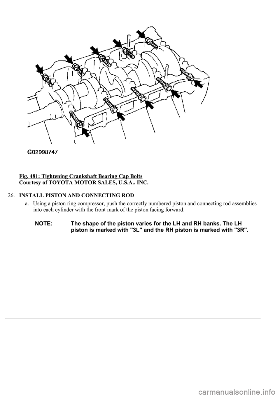
7. Install and uniformly tighten the 10 crankshaft bearing cap bolts.
Torque: 49 N.m (500 kgf.cm, 36 ft.lbf)
d. Check that the crankshaft turns smoothly.
e. Check the crankshaft thrust clearance (see step 6).
Page 3769 of 4500
Fig. 481: Tightening Crankshaft Bearing Cap Bolts
Courtesy of TOYOTA MOTOR SALES, U.S.A., INC.
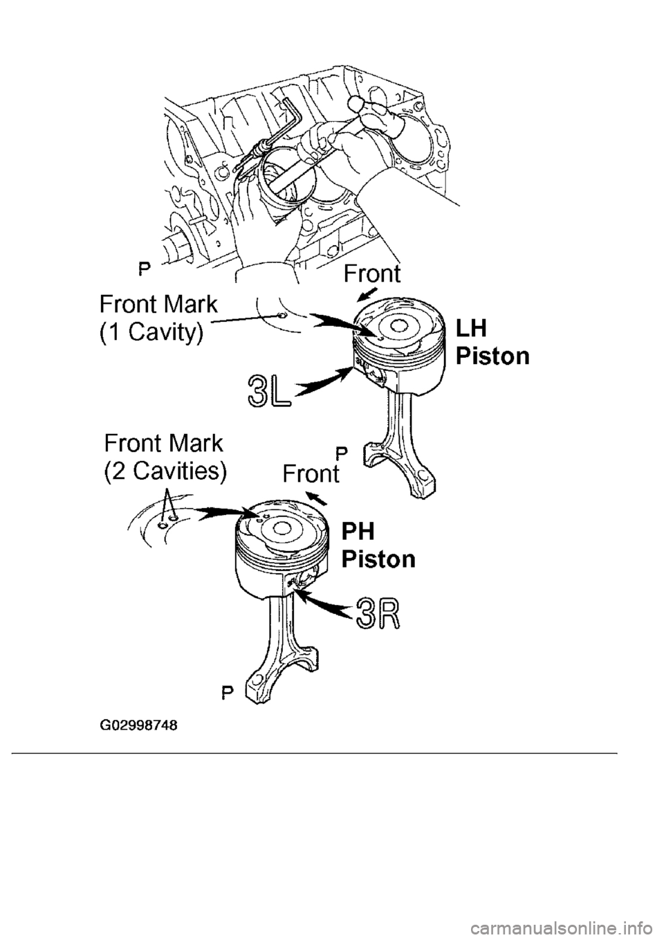
26.INSTALL PISTON AND CONNECTING ROD
a. Using a piston ring compressor, push the correctly numbered piston and connecting rod assemblies
into each cylinder with the front mark of the piston facing forward.
Page 3770 of 4500
Trending: Sp2, Spark plug firing order, Lock actuator, suspension, engine, C1752, Door lock
