LEXUS LS430 2003 Factory Repair Manual
Manufacturer: LEXUS, Model Year: 2003,
Model line: LS430,
Model: LEXUS LS430 2003
Pages: 4500, PDF Size: 87.45 MB
LEXUS LS430 2003 Factory Repair Manual
LS430 2003
LEXUS
LEXUS
https://www.carmanualsonline.info/img/36/57050/w960_57050-0.png
LEXUS LS430 2003 Factory Repair Manual
Trending: roof rack, brake pads, heater, center console, light, torque, rear seat back
Page 3751 of 4500
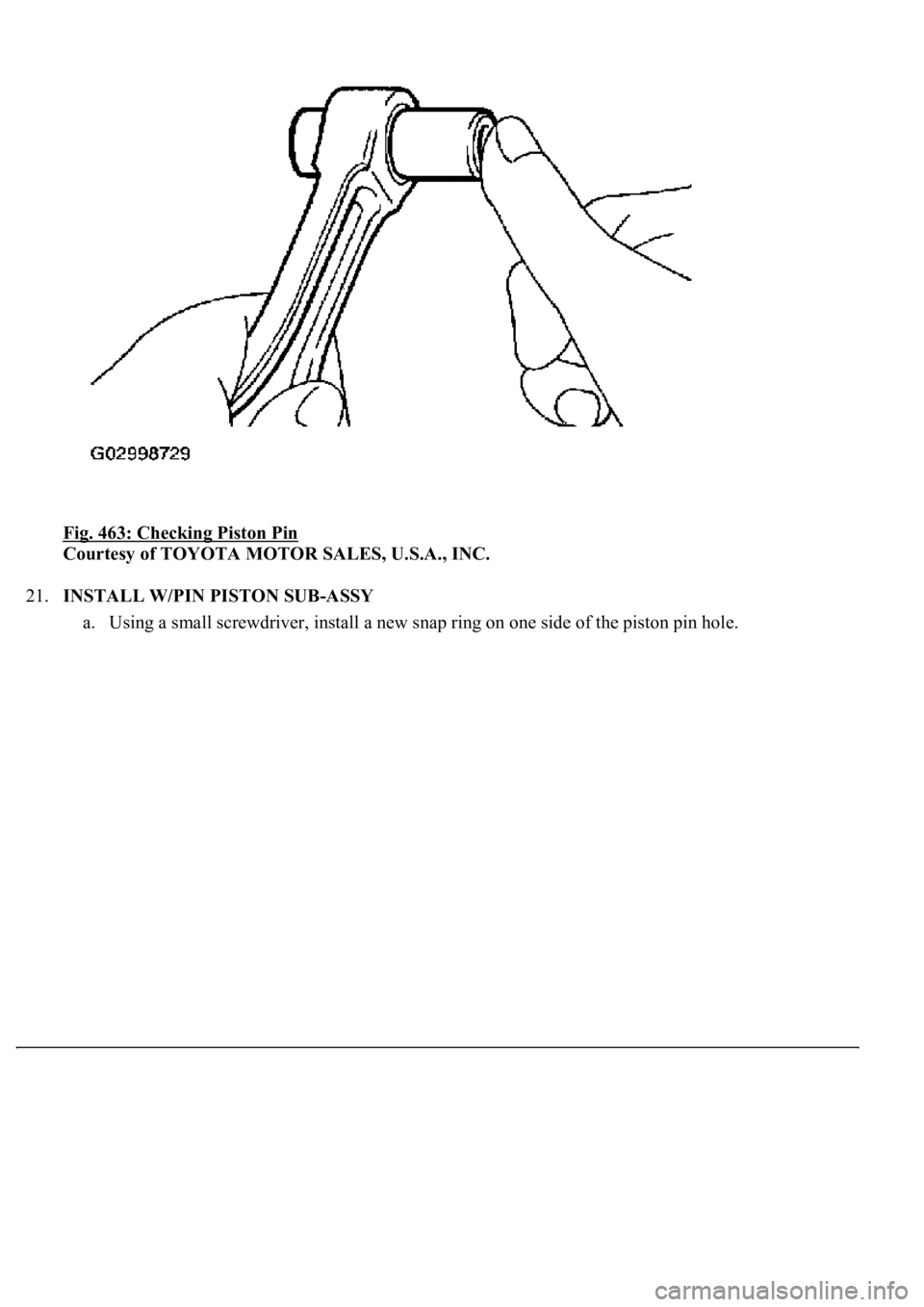
Fig. 463: Checking Piston Pin
Courtesy of TOYOTA MOTOR SALES, U.S.A., INC.
21.INSTALL W/PIN PISTON SUB-ASSY
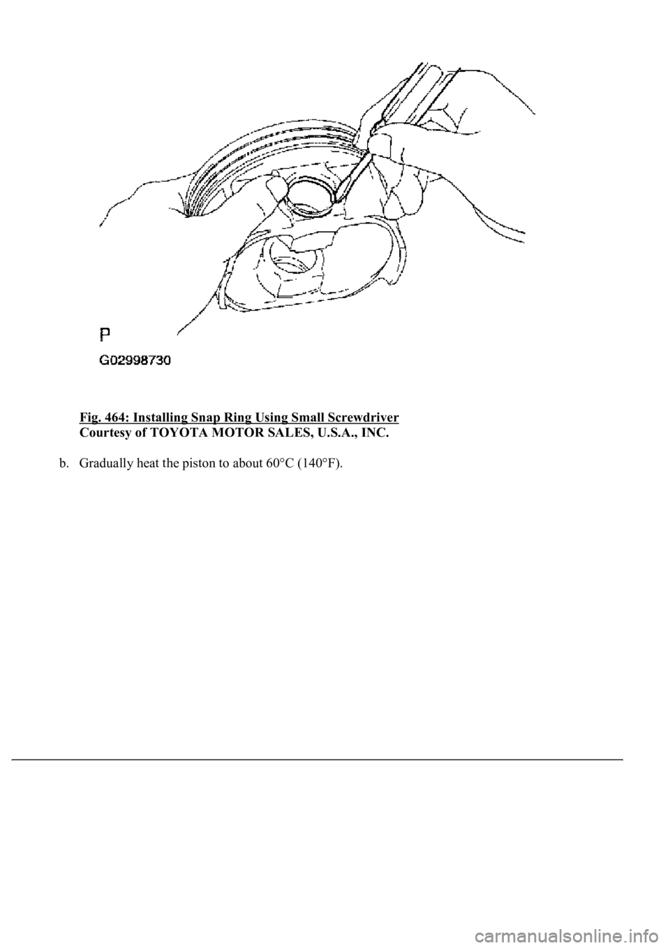
a. Using a small screwdriver, install a new snap ring on one side of the piston pin hole.
Page 3752 of 4500
Fig. 464: Installing Snap Ring Using Small Screwdriver
Courtesy of TOYOTA MOTOR SALES, U.S.A., INC.
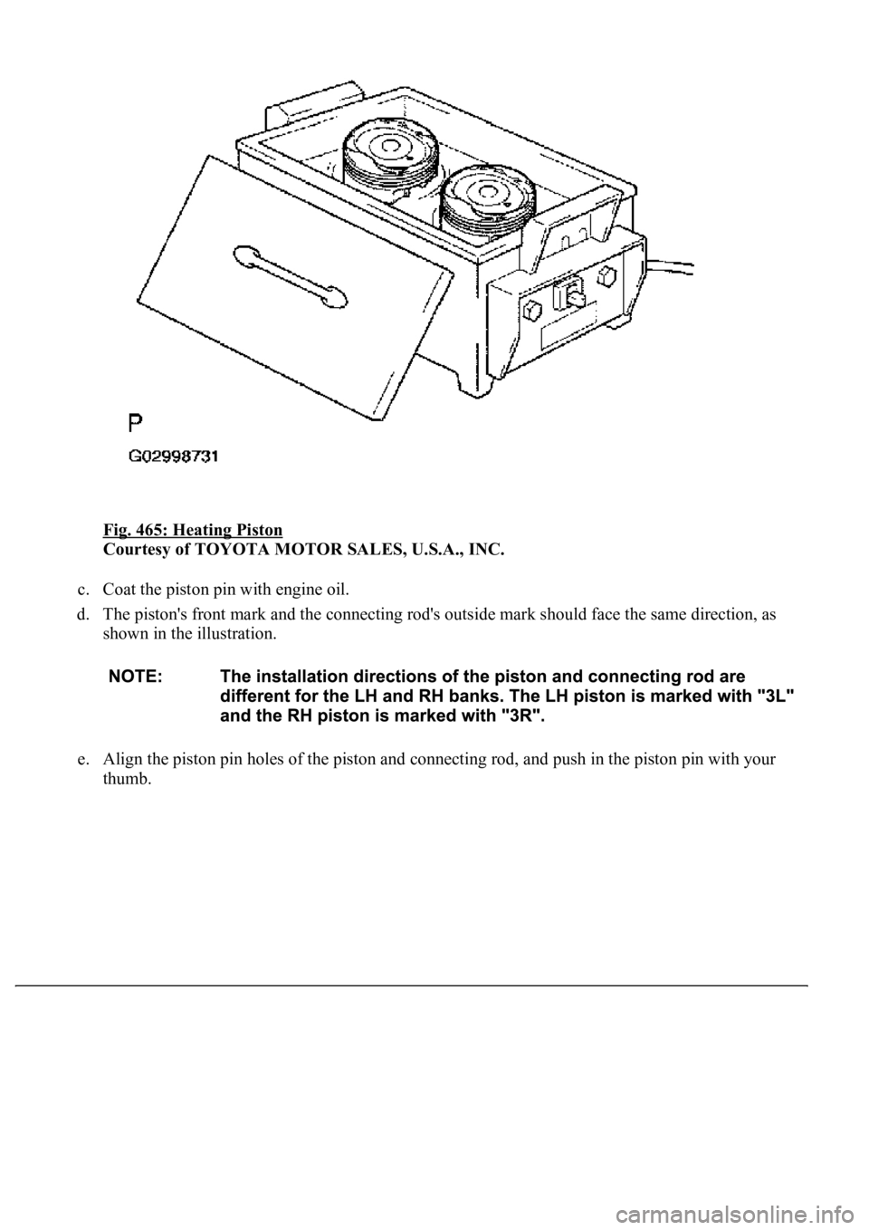
b.Gradually heat the piston to about 60°C (140°F).
Page 3753 of 4500
Fig. 465: Heating Piston
Courtesy of TOYOTA MOTOR SALES, U.S.A., INC.
c. Coat the piston pin with engine oil.
d. The piston's front mark and the connecting rod's outside mark should face the same direction, as
shown in the illustration.
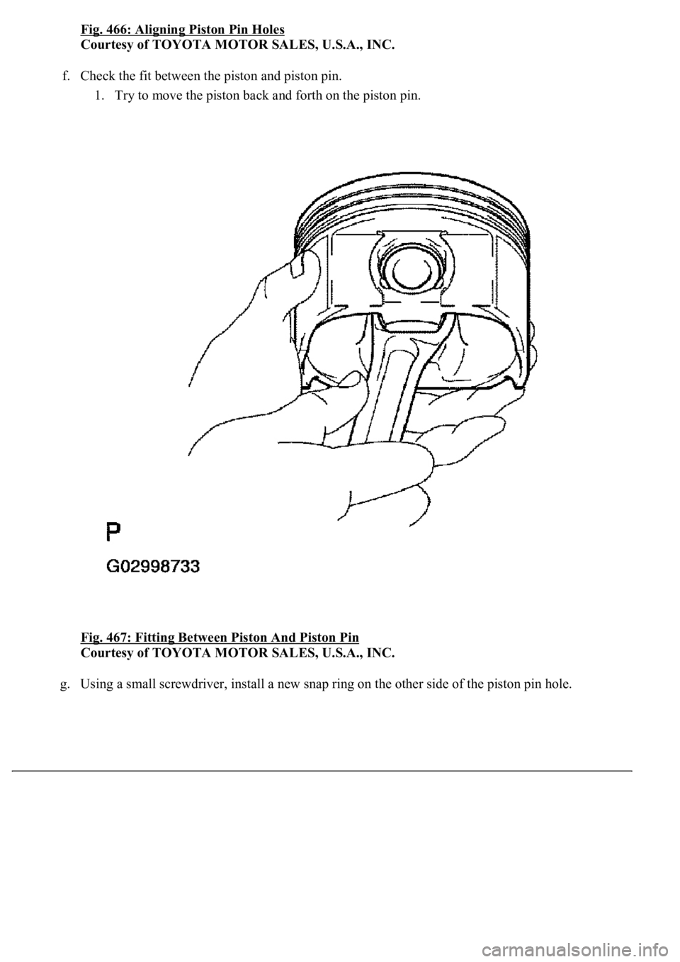
e. Align the piston pin holes of the piston and connecting rod, and push in the piston pin with your
thumb.
Page 3754 of 4500
Page 3755 of 4500
Fig. 466: Aligning Piston Pin Holes
Courtesy of TOYOTA MOTOR SALES, U.S.A., INC.
f. Check the fit between the piston and piston pin.
1. Try to move the piston back and forth on the piston pin.
Fig. 467: Fitting Between Piston And Piston Pin
Courtesy of TOYOTA MOTOR SALES, U.S.A., INC.
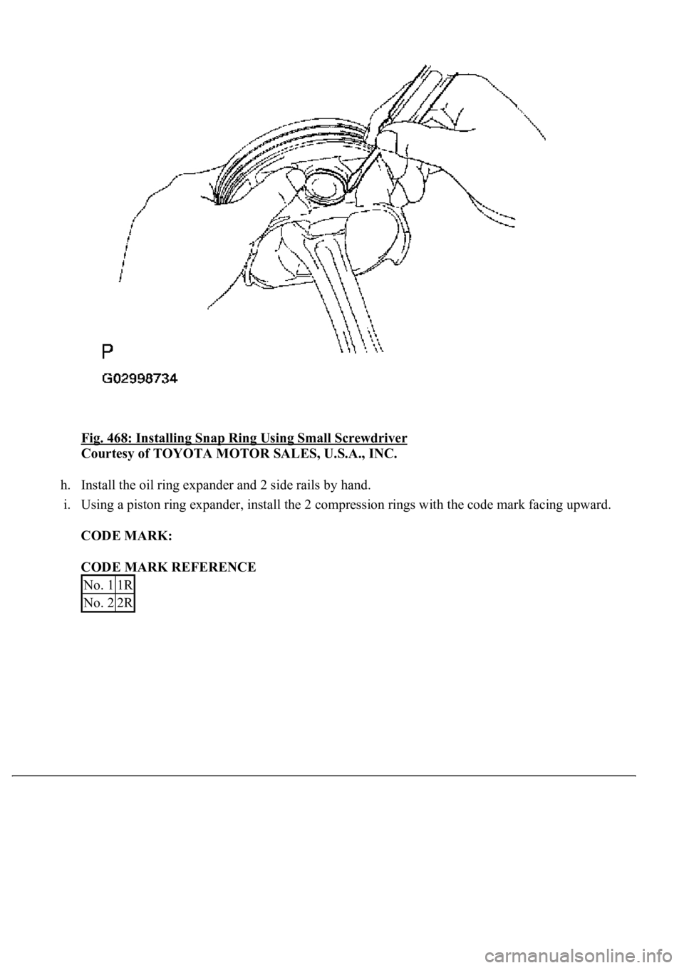
g.Using a small screwdriver, install a new snap ring on the other side of the piston pin hole.
Page 3756 of 4500
Fig. 468: Installing Snap Ring Using Small Screwdriver
Courtesy of TOYOTA MOTOR SALES, U.S.A., INC.
h. Install the oil ring expander and 2 side rails by hand.
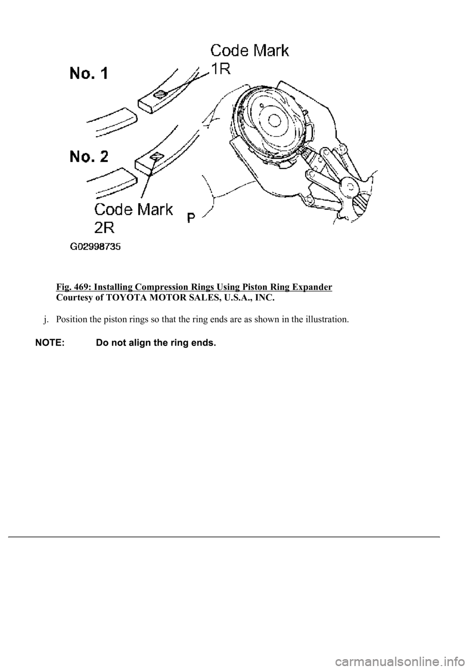
i. Using a piston ring expander, install the 2 compression rings with the code mark facing upward.
CODE MARK:
CODE MARK REFERENCE
No. 11R
No. 22R
Page 3757 of 4500
Fig. 469: Installing Compression Rings Using Piston Ring Expander
Courtesy of TOYOTA MOTOR SALES, U.S.A., INC.
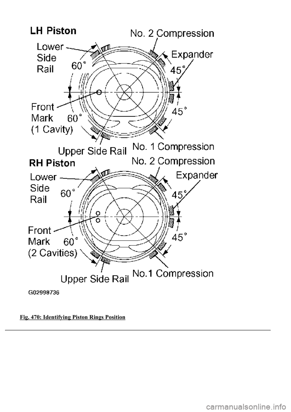
j. Position the piston rings so that the ring ends are as shown in the illustration.
Page 3758 of 4500
Fig. 470: Identifying Piston Rings Position
Page 3759 of 4500
Courtesy of TOYOTA MOTOR SALES, U.S.A., INC.
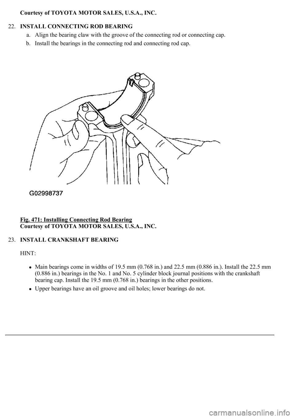
22.INSTALL CONNECTING ROD BEARING
a. Align the bearing claw with the groove of the connecting rod or connecting cap.
b. Install the bearings in the connecting rod and connecting rod cap.
Fig. 471: Installing Connecting Rod Bearing
Courtesy of TOYOTA MOTOR SALES, U.S.A., INC.
23.INSTALL CRANKSHAFT BEARING
HINT:
<00300044004c005100030045004800440055004c0051004a0056000300460052005000480003004c00510003005a004c00470057004b005600030052004900030014001c001100180003005000500003000b00130011001a0019001b0003004c0051001100
0c000300440051004700030015001500110018000300500050[ (0.886 in.). Install the 22.5 mm
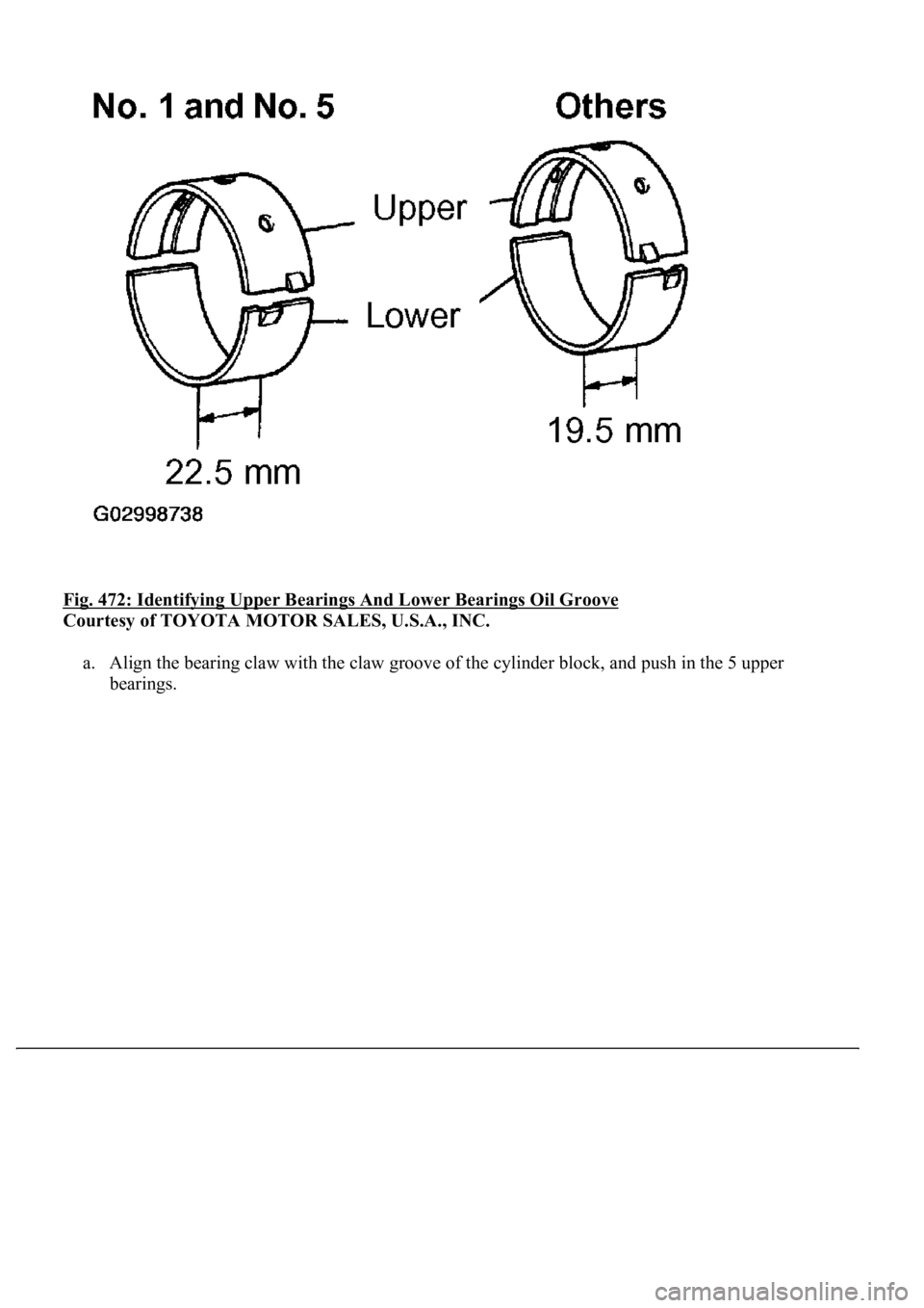
(0.886 in.) bearings in the No. 1 and No. 5 cylinder block journal positions with the crankshaft
<0045004800440055004c0051004a000300460044005300110003002c0051005600570044004f004f00030057004b004800030014001c001100180003005000500003000b00130011001a0019001b0003004c00510011000c00030045004800440055004c00
51004a00560003004c005100030057004b0048000300520057[her positions.
Upper bearings have an oil groove and oil holes; lower bearings do not.
Page 3760 of 4500
Fig. 472: Identifying Upper Bearings And Lower Bearings Oil Groove
Courtesy of TOYOTA MOTOR SALES, U.S.A., INC.
a. Align the bearing claw with the claw groove of the cylinder block, and push in the 5 upper
bearings.
Trending: ABS, oil temperature, roof rack, shock absorber, airbag, ESP, fuel pressure
