LEXUS LS430 2003 Factory Owner's Guide
Manufacturer: LEXUS, Model Year: 2003, Model line: LS430, Model: LEXUS LS430 2003Pages: 4500, PDF Size: 87.45 MB
Page 31 of 4500
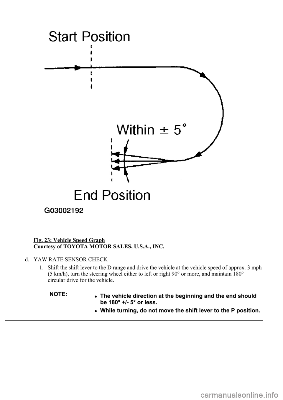
Fig. 23: Vehicle Speed Graph
Courtesy of TOYOTA MOTOR SALES, U.S.A., INC.
d. YAW RATE SENSOR CHECK
1. Shift the shift lever to the D range and drive the vehicle at the vehicle speed of approx. 3 mph
(5 km/h), turn the steering wheel either to left or right 90° or more, and maintain 180°
circular drive for the vehicle.
Page 32 of 4500
HINT:
The turning direction is not important.
Turning should be completed within 20 seconds. However, it is possible to change the
vehicle speed, stop or move backward.
2. Stop the vehicle and shift the shift lever to the P position, check that the skid control buzzer
sounds for 3 sec.
HINT:
If the skid control buzzer sounds, the sensor check is completed normally.
If the skid control buzzer does not sound, check the skid control buzzer circuit (see SKID
CONTROL BUZZER CIRCUIT ), then perform the sensor check again.
If the skid control buzzer still does not sound, there is a malfunction in the VSC sensor, so
check the DTC.
Drive the vehicle in a 180° circle. At the end of the turn, the direction of the vehicle should
be within 180° +/- 5° of its start position.
Do not spin the wheels.
Even if the VSC sensor check is completed normally, the multi-information displays "VSC
Test" (test mode).
Page 33 of 4500
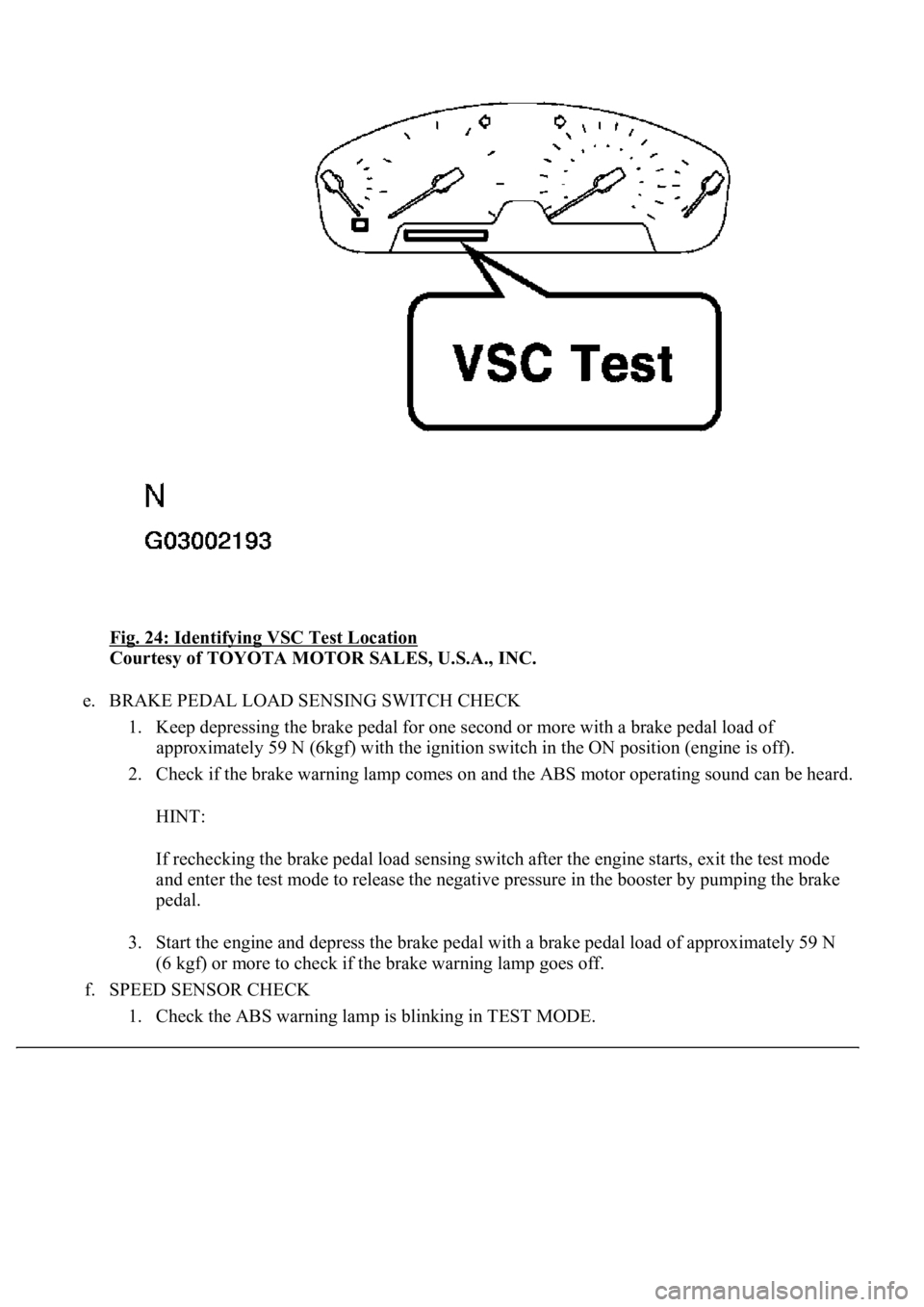
Fig. 24: Identifying VSC Test Location
Courtesy of TOYOTA MOTOR SALES, U.S.A., INC.
e. BRAKE PEDAL LOAD SENSING SWITCH CHECK
1. Keep depressing the brake pedal for one second or more with a brake pedal load of
approximately 59 N (6kgf) with the ignition switch in the ON position (engine is off).
2. Check if the brake warning lamp comes on and the ABS motor operating sound can be heard.
HINT:
If rechecking the brake pedal load sensing switch after the engine starts, exit the test mode
and enter the test mode to release the negative pressure in the booster by pumping the brake
pedal.
3. Start the engine and depress the brake pedal with a brake pedal load of approximately 59 N
(6 kgf) or more to check if the brake warning lamp goes off.
f. SPEED SENSOR CHECK
1. Check the ABS warnin
g lamp is blinking in TEST MODE.
Page 34 of 4500
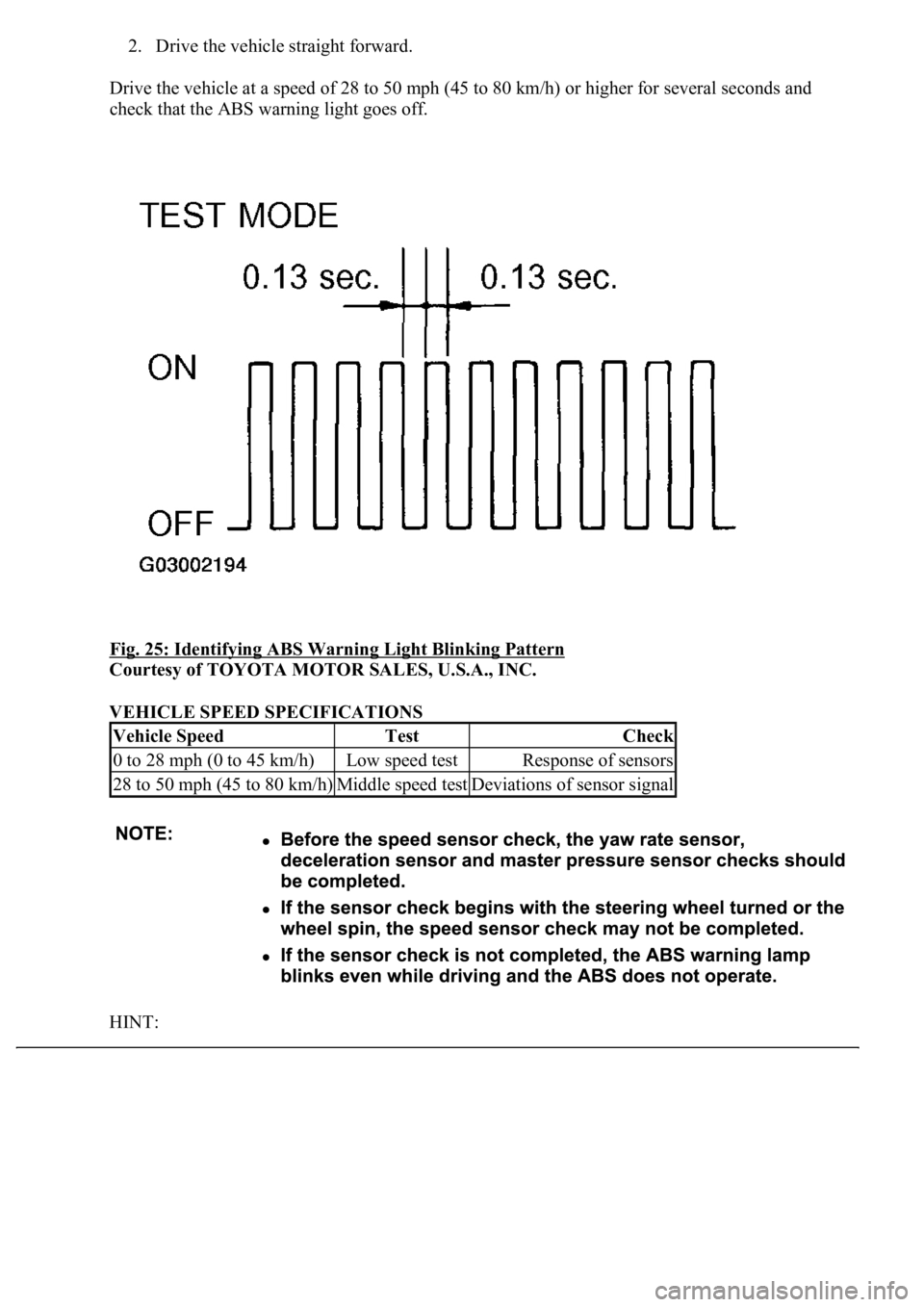
2. Drive the vehicle straight forward.
Drive the vehicle at a speed of 28 to 50 mph (45 to 80 km/h) or higher for several seconds and
check that the ABS warning light goes off.
Fig. 25: Identifying ABS Warning Light Blinking Pattern
Courtesy of TOYOTA MOTOR SALES, U.S.A., INC.
VEHICLE SPEED SPECIFICATIONS
HINT:
Vehicle SpeedTestCheck
0 to 28 mph (0 to 45 km/h)Low speed testResponse of sensors
28 to 50 mph (45 to 80 km/h)Middle speed testDeviations of sensor signal
Page 35 of 4500
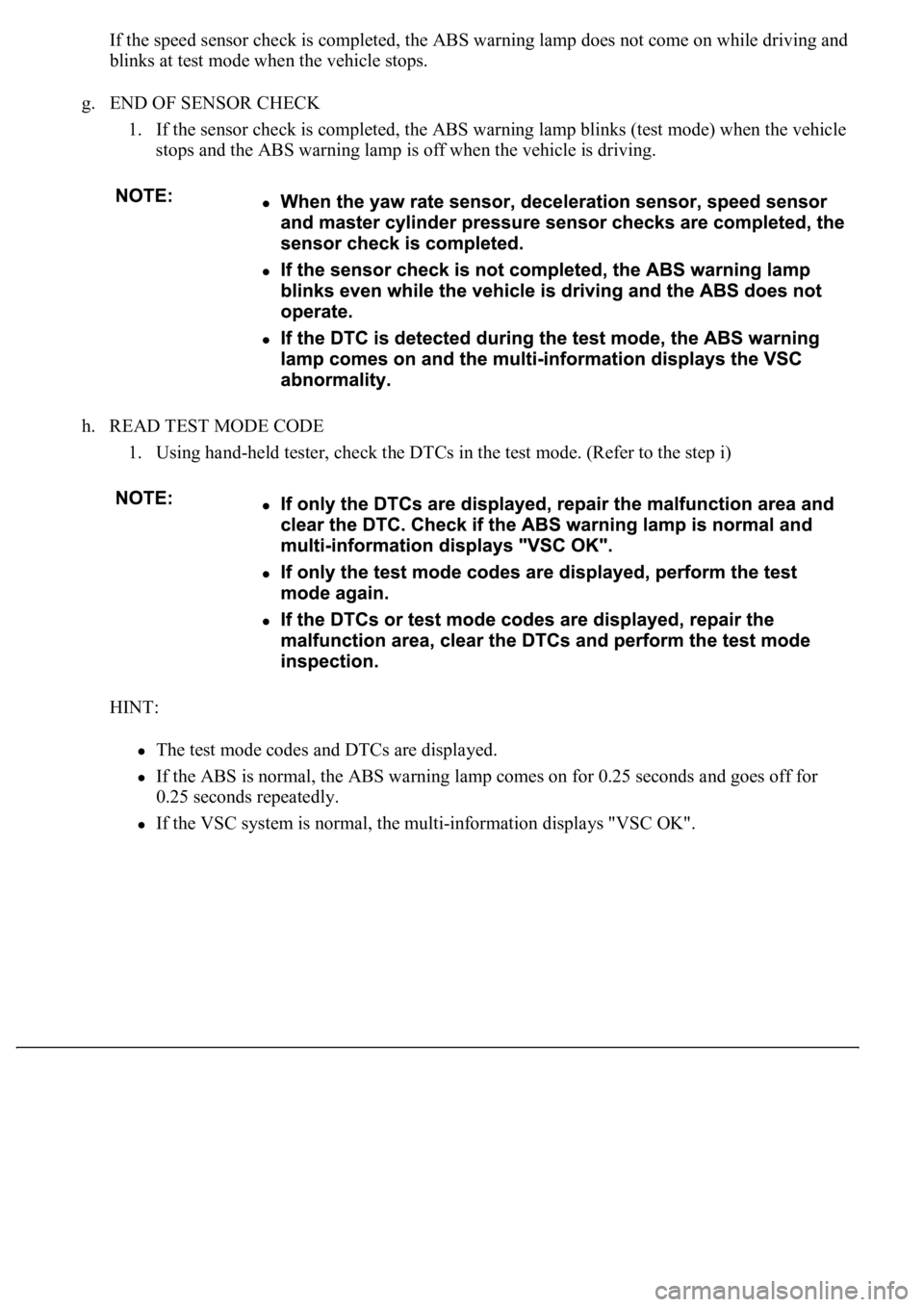
If the speed sensor check is completed, the ABS warning lamp does not come on while driving and
blinks at test mode when the vehicle stops.
g. END OF SENSOR CHECK
1. If the sensor check is completed, the ABS warning lamp blinks (test mode) when the vehicle
stops and the ABS warning lamp is off when the vehicle is driving.
h. READ TEST MODE CODE
1. Using hand-held tester, check the DTCs in the test mode. (Refer to the step i)
HINT:
The test mode codes and DTCs are displayed.
If the ABS is normal, the ABS warning lamp comes on for 0.25 seconds and goes off for
0.25 seconds repeatedly.
If the VSC system is normal, the multi-information displays "VSC OK".
Page 36 of 4500
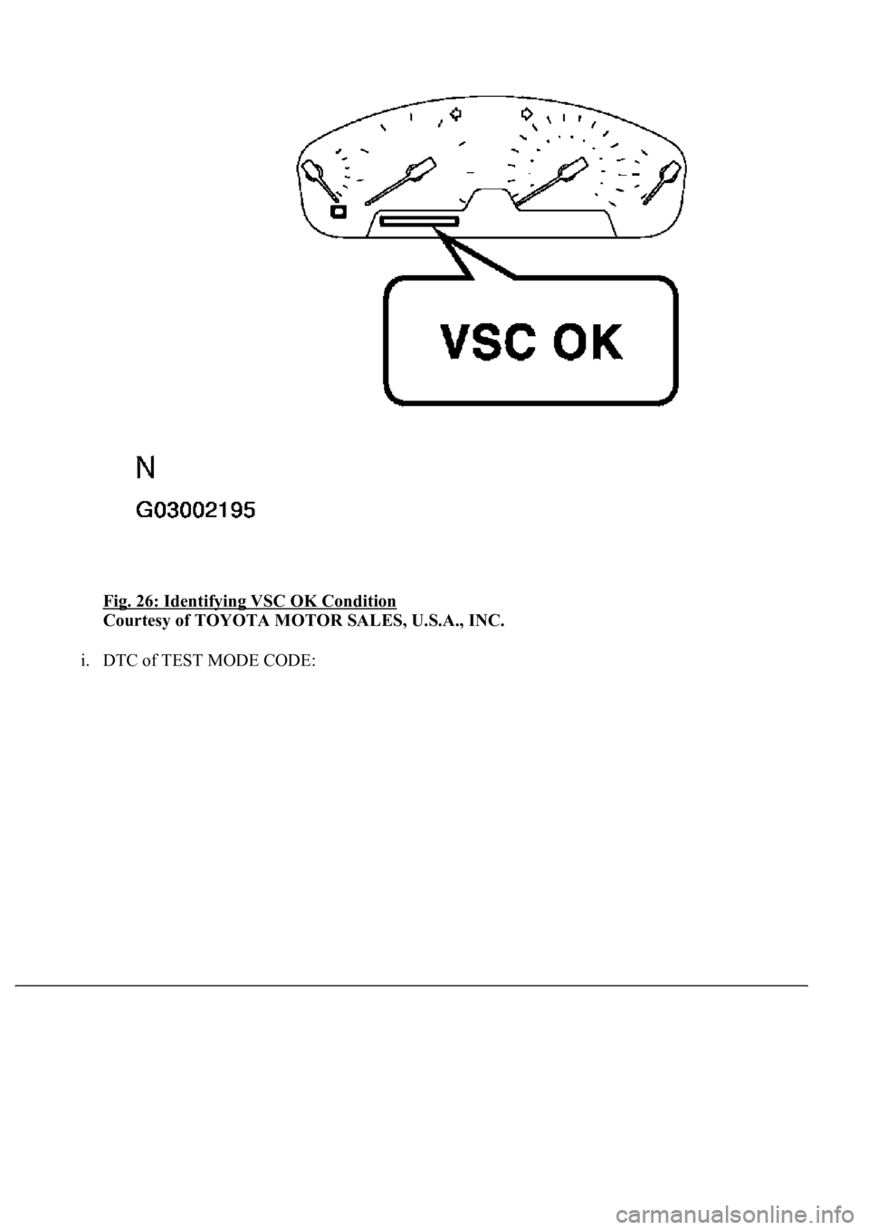
Fig. 26: Identifying VSC OK Condition
Courtesy of TOYOTA MOTOR SALES, U.S.A., INC.
i. DTC of TEST MODE CODE:
Page 37 of 4500
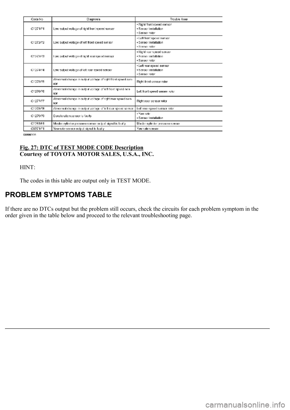
Fig. 27: DTC of TEST MODE CODE Description
Courtesy of TOYOTA MOTOR SALES, U.S.A., INC.
HINT:
The codes in this table are output only in TEST MODE.
If there are no DTCs output but the problem still occurs, check the circuits for each problem symptom in the
order
given in the table below and proceed to the relevant troubleshooting page.
Page 38 of 4500
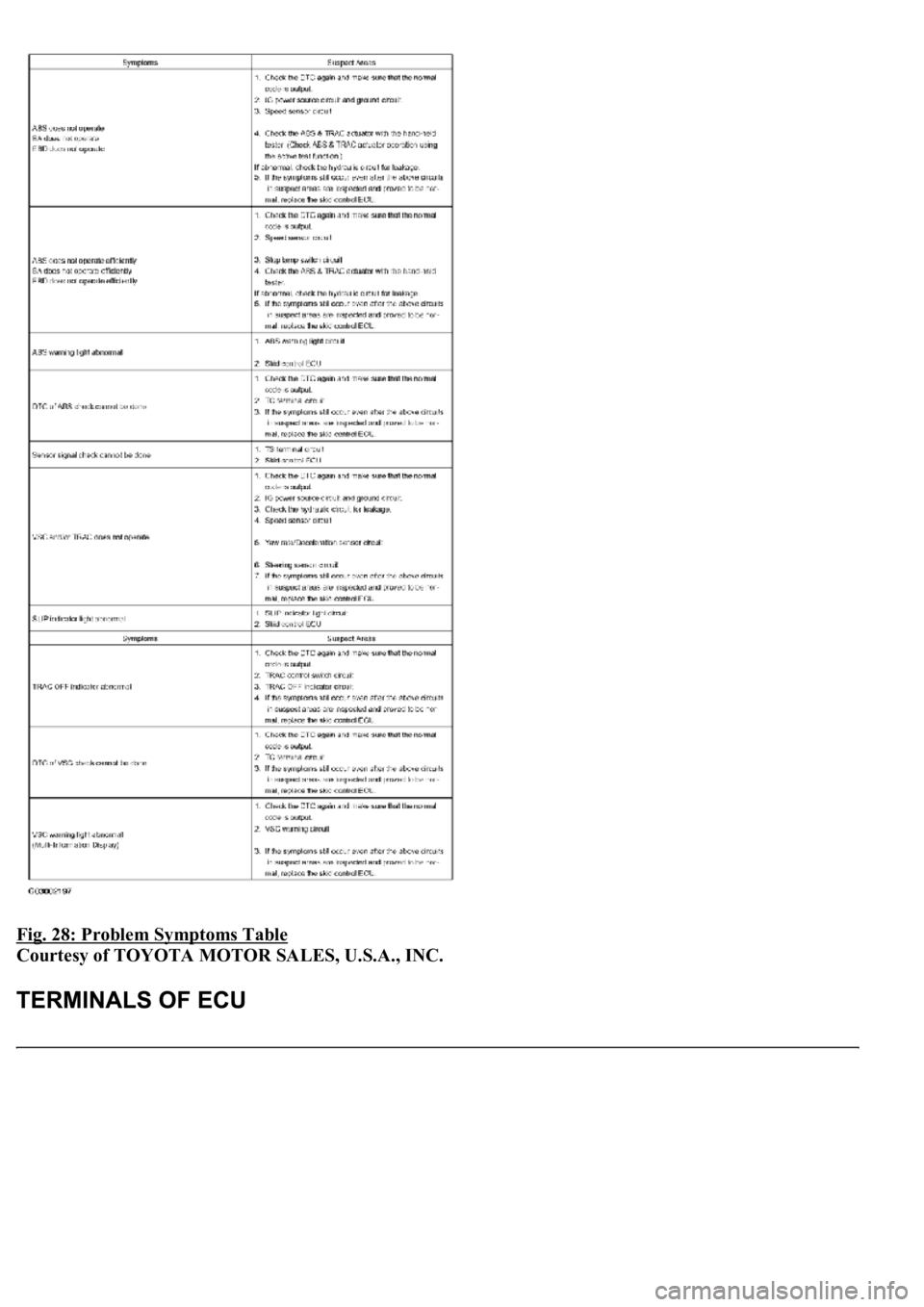
Fig. 28: Problem Symptoms Table
Courtesy of TOYOTA MOTOR SALES, U.S.A., INC.
Page 39 of 4500
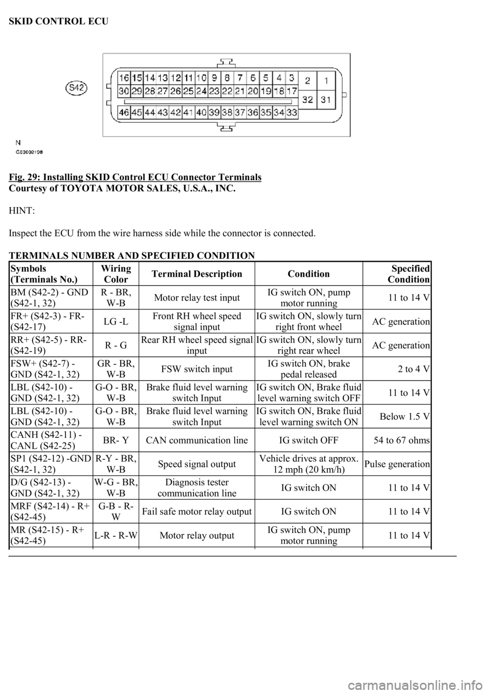
SKID CONTROL ECU
Fig. 29: Installing SKID Control ECU Connector Terminals
Courtesy of TOYOTA MOTOR SALES, U.S.A., INC.
HINT:
Inspect the ECU from the wire harness side while the connector is connected.
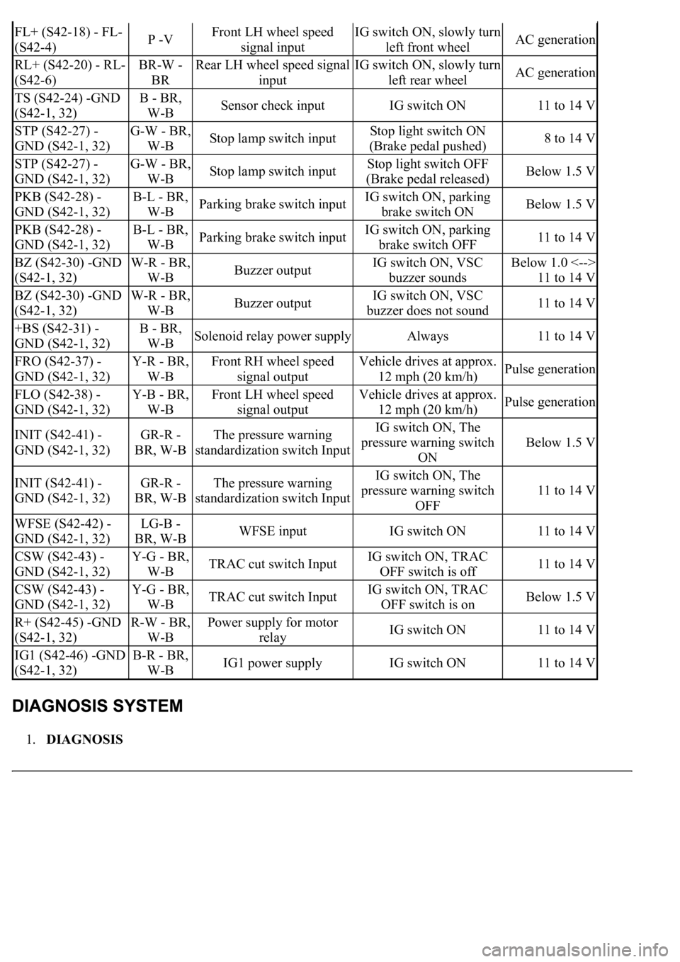
TERMINALS NUMBER AND SPECIFIED CONDITION
Symbols
(Terminals No.)Wiring
ColorTerminal DescriptionConditionSpecified
Condition
BM (S42-2) - GND
(S42-1, 32)R - BR,
W-BMotor relay test inputIG switch ON, pump
motor running11 to 14 V
FR+ (S42-3) - FR-
(S42-17)LG -LFront RH wheel speed
signal inputIG switch ON, slowly turn
right front wheelAC generation
RR+ (S42-5) - RR-
(S42-19)R - GRear RH wheel speed signal
inputIG switch ON, slowly turn
right rear wheelAC generation
FSW+ (S42-7) -
GND (S42-1, 32)GR - BR,
W-BFSW switch inputIG switch ON, brake
pedal released2 to 4 V
LBL (S42-10) -
GND (S42-1, 32)G-O - BR,
W-BBrake fluid level warning
switch InputIG switch ON, Brake fluid
level warning switch OFF11 to 14 V
LBL (S42-10) -
GND (S42-1, 32)G-O - BR,
W-BBrake fluid level warning
switch InputIG switch ON, Brake fluid
level warning switch ONBelow 1.5 V
CANH (S42-11) -
CANL (S42-25)BR- YCAN communication lineIG switch OFF54 to 67 ohms
SP1 (S42-12) -GND
(S42-1, 32)R-Y - BR,
W-BSpeed signal outputVehicle drives at approx.
12 mph (20 km/h)Pulse generation
D/G (S42-13) -
GND (S42-1, 32)W-G - BR,
W-BDiagnosis tester
communication lineIG switch ON11 to 14 V
MRF (S42-14) - R+
(S42-45)G-B - R-
WFail safe motor relay outputIG switch ON11 to 14 V
MR (S42-15) - R+
(S42-45)L-R - R-WMotor relay outputIG switch ON, pump
motor running11 to 14 V
Page 40 of 4500
1.DIAGNOSIS
FL+ (S42-18) - FL-
(S42-4)P -VFront LH wheel speed
signal inputIG switch ON, slowly turn
left front wheelAC generation
RL+ (S42-20) - RL-
(S42-6)BR-W -
BRRear LH wheel speed signal
inputIG switch ON, slowly turn
left rear wheelAC generation
TS (S42-24) -GND
(S42-1, 32)B - BR,
W-BSensor check inputIG switch ON11 to 14 V
STP (S42-27) -
GND (S42-1, 32)G-W - BR,
W-BStop lamp switch inputStop light switch ON
(Brake pedal pushed)8 to 14 V
STP (S42-27) -
GND (S42-1, 32)G-W - BR,
W-BStop lamp switch inputStop light switch OFF
(Brake pedal released)Below 1.5 V
PKB (S42-28) -
GND (S42-1, 32)B-L - BR,
W-BParking brake switch inputIG switch ON, parking
brake switch ONBelow 1.5 V
PKB (S42-28) -
GND (S42-1, 32)B-L - BR,
W-BParking brake switch inputIG switch ON, parking
brake switch OFF11 to 14 V
BZ (S42-30) -GND
(S42-1, 32)W-R - BR,
W-BBuzzer outputIG switch ON, VSC
buzzer soundsBelow 1.0 <-->
11 to 14 V
BZ (S42-30) -GND
(S42-1, 32)W-R - BR,
W-BBuzzer outputIG switch ON, VSC
buzzer does not sound11 to 14 V
+BS (S42-31) -
GND (S42-1, 32)B - BR,
W-BSolenoid relay power supplyAlways11 to 14 V
FRO (S42-37) -
GND (S42-1, 32)Y-R - BR,
W-BFront RH wheel speed
signal outputVehicle drives at approx.
12 mph (20 km/h)Pulse generation
FLO (S42-38) -
GND (S42-1, 32)Y-B - BR,
W-BFront LH wheel speed
signal outputVehicle drives at approx.
12 mph (20 km/h)Pulse generation
INIT (S42-41) -
GND (S42-1, 32)GR-R -
BR, W-BThe pressure warning
standardization switch InputIG switch ON, The
pressure warning switch
ON
Below 1.5 V
INIT (S42-41) -
GND (S42-1, 32)GR-R -
BR, W-BThe pressure warning
standardization switch InputIG switch ON, The
pressure warning switch
OFF
11 to 14 V
WFSE (S42-42) -
GND (S42-1, 32)LG-B -
BR, W-BWFSE inputIG switch ON11 to 14 V
CSW (S42-43) -
GND (S42-1, 32)Y-G - BR,
W-BTRAC cut switch InputIG switch ON, TRAC
OFF switch is off11 to 14 V
CSW (S42-43) -
GND (S42-1, 32)Y-G - BR,
W-BTRAC cut switch InputIG switch ON, TRAC
OFF switch is onBelow 1.5 V
R+ (S42-45) -GND
(S42-1, 32)R-W - BR,
W-BPower supply for motor
relayIG switch ON11 to 14 V
IG1 (S42-46) -GND
(S42-1, 32)B-R - BR,
W-BIG1 power supplyIG switch ON11 to 14 V