LEXUS LS430 2003 Factory Workshop Manual
Manufacturer: LEXUS, Model Year: 2003,
Model line: LS430,
Model: LEXUS LS430 2003
Pages: 4500, PDF Size: 87.45 MB
LEXUS LS430 2003 Factory Workshop Manual
LS430 2003
LEXUS
LEXUS
https://www.carmanualsonline.info/img/36/57050/w960_57050-0.png
LEXUS LS430 2003 Factory Workshop Manual
Trending: Rear, service indicator, cruise control, tires, transmission oil, differential, service
Page 51 of 4500
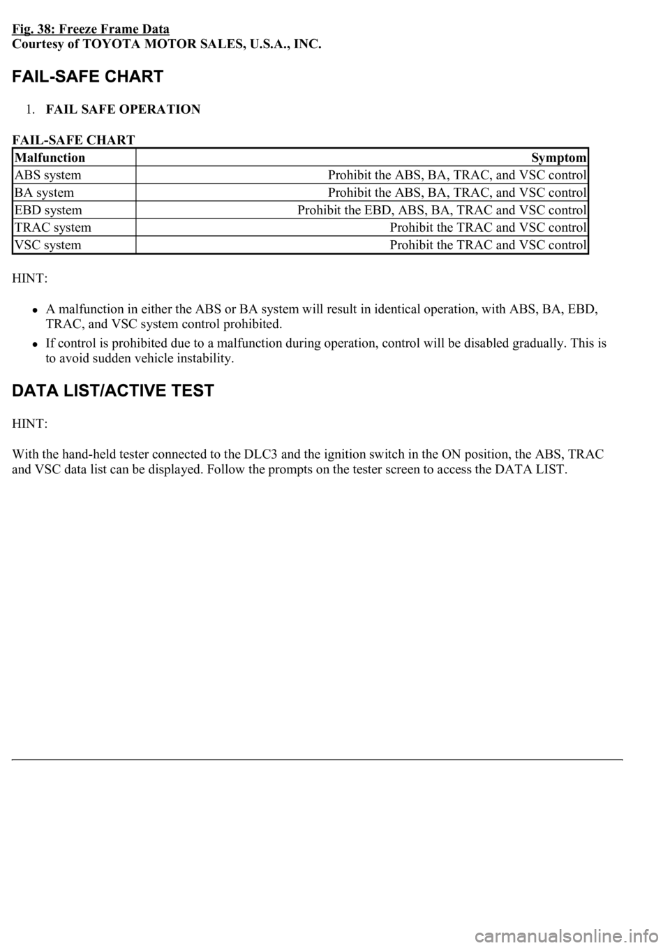
Fig. 38: Freeze Frame Data
Courtesy of TOYOTA MOTOR SALES, U.S.A., INC.
1.FAIL SAFE OPERATION
FAIL-SAFE CHART
HINT:
A malfunction in either the ABS or BA system will result in identical operation, with ABS, BA, EBD,
TRAC, and VSC system control prohibited.
If control is prohibited due to a malfunction during operation, control will be disabled gradually. This is
to avoid sudden vehicle instability.
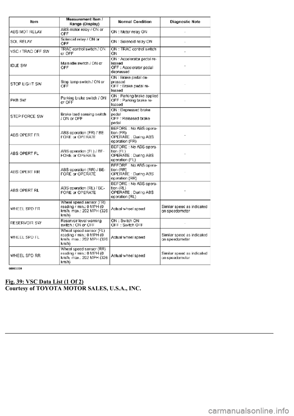
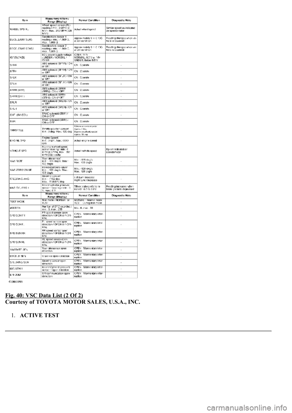
HINT:
With the hand-held tester connected to the DLC3 and the ignition switch in the ON position, the ABS, TRAC
and VSC data list can be displa
yed. Follow the prompts on the tester screen to access the DATA LIST.
MalfunctionSymptom
ABS systemProhibit the ABS, BA, TRAC, and VSC control
BA systemProhibit the ABS, BA, TRAC, and VSC control
EBD systemProhibit the EBD, ABS, BA, TRAC and VSC control
TRAC systemProhibit the TRAC and VSC control
VSC systemProhibit the TRAC and VSC control
Page 52 of 4500
Fig. 39: VSC Data List (1 Of 2)
Courtesy of TOYOTA MOTOR SALES, U.S.A., INC.
Page 53 of 4500
Fig. 40: VSC Data List (2 Of 2)
Courtesy of TOYOTA MOTOR SALES, U.S.A., INC.
1.ACTIVE TEST
Page 54 of 4500
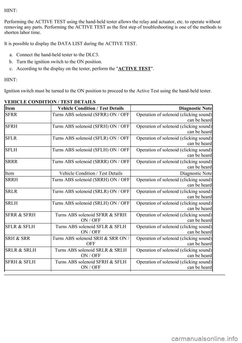
HINT:
Performing the ACTIVE TEST using the hand-held tester allows the relay and actuator, etc. to operate without
removing any parts. Performing the ACTIVE TEST as the first step of troubleshooting is one of the methods to
shorten labor time.
It is possible to display the DATA LIST during the ACTIVE TEST.
a. Connect the hand-held tester to the DLC3.
b. Turn the ignition switch to the ON position.
c. According to the display on the tester, perform the "ACTIVE TEST
".
HINT:
Ignition switch must be turned to the ON position to proceed to the Active Test using the hand-held tester.
VEHICLE CONDITION / TEST DETAILS
ItemVehicle Condition / Test DetailsDiagnostic Note
SFRRTurns ABS solenoid (SFRR) ON / OFFOperation of solenoid (clicking sound)
can be heard
SFRHTurns ABS solenoid (SFRH) ON / OFFOperation of solenoid (clicking sound)
can be heard
SFLRTurns ABS solenoid (SFLR) ON / OFFOperation of solenoid (clicking sound)
can be heard
SFLHTurns ABS solenoid (SFLH) ON / OFFOperation of solenoid (clicking sound)
can be heard
SRRRTurns ABS solenoid (SRRR) ON / OFFOperation of solenoid (clicking sound)
can be heard
ItemVehicle Condition / Test DetailsDiagnostic Note
SRRHTurns ABS solenoid (SRRH) ON / OFFOperation of solenoid (clicking sound)
can be heard
SRLRTurns ABS solenoid (SRLR) ON / OFFOperation of solenoid (clicking sound)
can be heard
SRLHTurns ABS solenoid (SRLH) ON / OFFOperation of solenoid (clicking sound)
can be heard
SFRR & SFRHTurns ABS solenoid SFRR & SFRH
ON / OFFOperation of solenoid (clicking sound)
can be heard
SFLR & SFLHTurns ABS solenoid SFLR & SFLH
ON / OFFOperation of solenoid (clicking sound)
can be heard
SRH & SRRTurns ABS solenoid SRH & SRR ON /
OFFOperation of solenoid (clicking sound)
can be heard
SRLR & SRLHTurns ABS solenoid SRLR & SRLH
ON / OFFOperation of solenoid (clicking sound)
can be heard
SFRH & SFLHTurns ABS solenoid SFRH & SFLH
ON / OFFOperation of solenoid (clicking sound)
can be heard
Page 55 of 4500
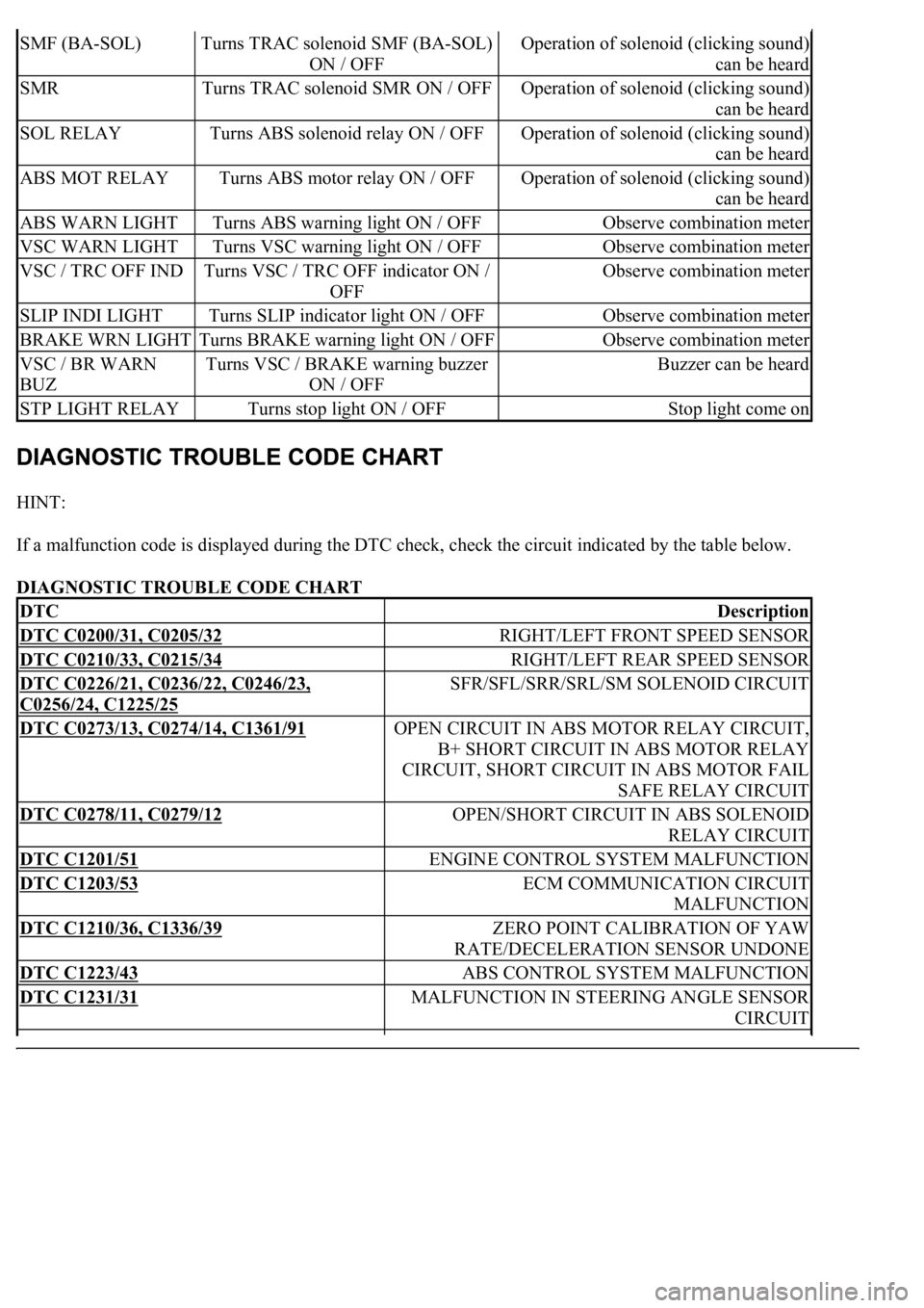
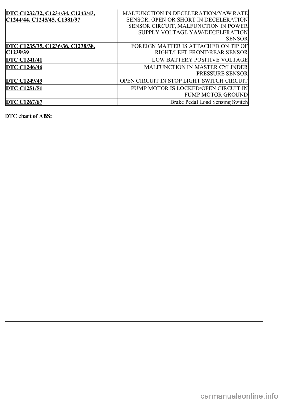
HINT:
If a malfunction code is displayed during the DTC check, check the circuit indicated by the table below.
DIAGNOSTIC TROUBLE CODE CHART
SMF (BA-SOL)Turns TRAC solenoid SMF (BA-SOL)
ON / OFFOperation of solenoid (clicking sound)
can be heard
SMRTurns TRAC solenoid SMR ON / OFFOperation of solenoid (clicking sound)
can be heard
SOL RELAYTurns ABS solenoid relay ON / OFFOperation of solenoid (clicking sound)
can be heard
ABS MOT RELAYTurns ABS motor relay ON / OFFOperation of solenoid (clicking sound)
can be heard
ABS WARN LIGHTTurns ABS warning light ON / OFFObserve combination meter
VSC WARN LIGHTTurns VSC warning light ON / OFFObserve combination meter
VSC / TRC OFF INDTurns VSC / TRC OFF indicator ON /
OFFObserve combination meter
SLIP INDI LIGHTTurns SLIP indicator light ON / OFFObserve combination meter
BRAKE WRN LIGHTTurns BRAKE warning light ON / OFFObserve combination meter
VSC / BR WARN
BUZTurns VSC / BRAKE warning buzzer
ON / OFFBuzzer can be heard
STP LIGHT RELAYTurns stop light ON / OFFStop light come on
DTCDescription
DTC C0200/31, C0205/32RIGHT/LEFT FRONT SPEED SENSOR
DTC C0210/33, C0215/34RIGHT/LEFT REAR SPEED SENSOR
DTC C0226/21, C0236/22, C0246/23,
C0256/24, C1225/25
SFR/SFL/SRR/SRL/SM SOLENOID CIRCUIT
DTC C0273/13, C0274/14, C1361/91OPEN CIRCUIT IN ABS MOTOR RELAY CIRCUIT,
B+ SHORT CIRCUIT IN ABS MOTOR RELAY
CIRCUIT, SHORT CIRCUIT IN ABS MOTOR FAIL
SAFE RELAY CIRCUIT
DTC C0278/11, C0279/12OPEN/SHORT CIRCUIT IN ABS SOLENOID
RELAY CIRCUIT
DTC C1201/51ENGINE CONTROL SYSTEM MALFUNCTION
DTC C1203/53ECM COMMUNICATION CIRCUIT
MALFUNCTION
DTC C1210/36, C1336/39ZERO POINT CALIBRATION OF YAW
RATE/DECELERATION SENSOR UNDONE
DTC C1223/43ABS CONTROL SYSTEM MALFUNCTION
DTC C1231/31MALFUNCTION IN STEERING ANGLE SENSOR
CIRCUIT
Page 56 of 4500
DTC chart of ABS:
DTC C1232/32, C1234/34, C1243/43,
C1244/44, C1245/45, C1381/97
MALFUNCTION IN DECELERATION/YAW RATE
SENSOR, OPEN OR SHORT IN DECELERATION
SENSOR CIRCUIT, MALFUNCTION IN POWER
SUPPLY VOLTAGE YAW/DECELERATION
SENSOR
DTC C1235/35, C1236/36, C1238/38,
C1239/39
FOREIGN MATTER IS ATTACHED ON TIP OF
RIGHT/LEFT FRONT/REAR SENSOR
DTC C1241/41LOW BATTERY POSITIVE VOLTAGE
DTC C1246/46MALFUNCTION IN MASTER CYLINDER
PRESSURE SENSOR
DTC C1249/49OPEN CIRCUIT IN STOP LIGHT SWITCH CIRCUIT
DTC C1251/51PUMP MOTOR IS LOCKED/OPEN CIRCUIT IN
PUMP MOTOR GROUND
DTC C1267/67Brake Pedal Load Sensing Switch
Page 57 of 4500
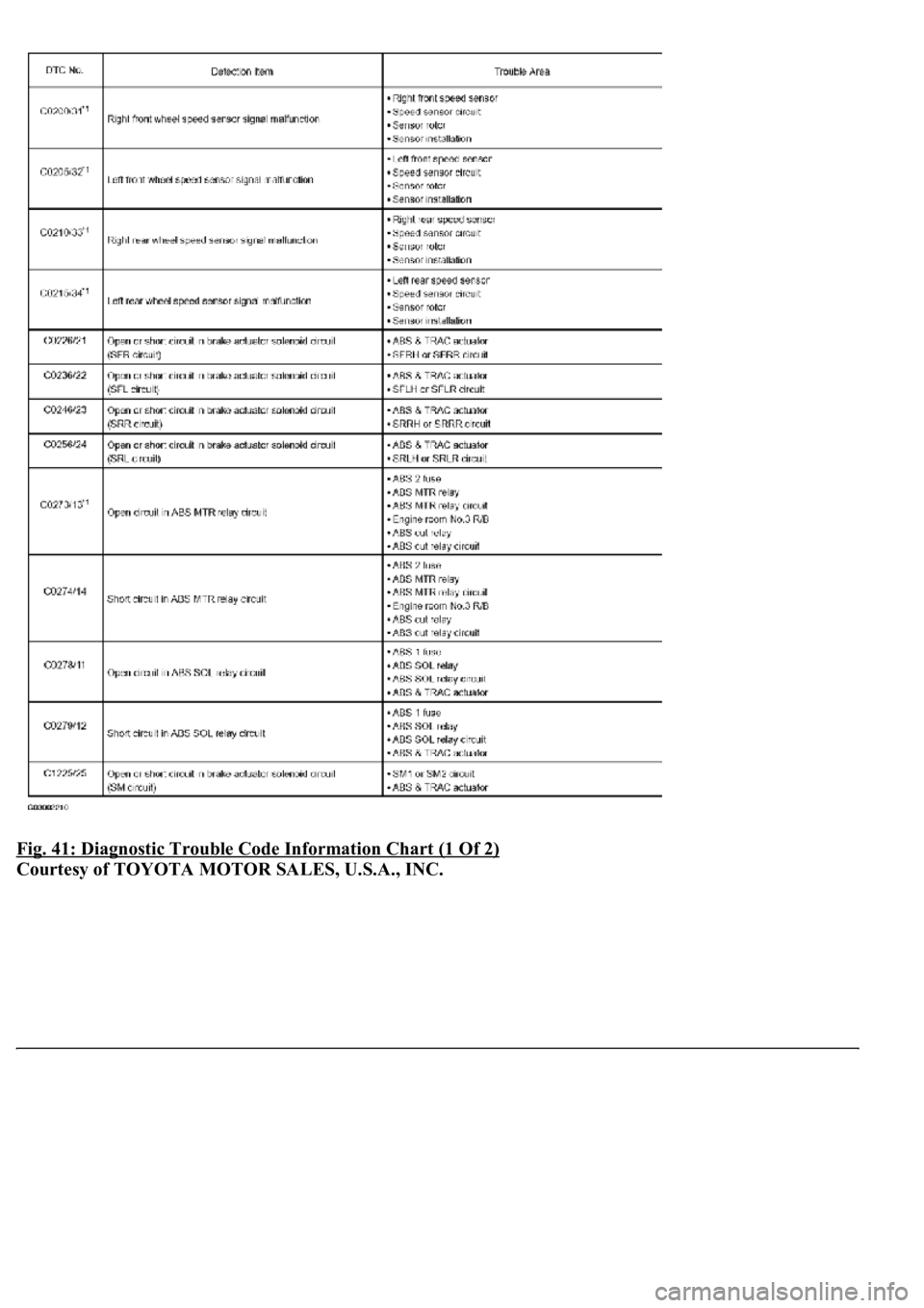
Fig. 41: Diagnostic Trouble Code Information Chart (1 Of 2)
Courtesy of TOYOTA MOTOR SALES, U.S.A., INC.
Page 58 of 4500
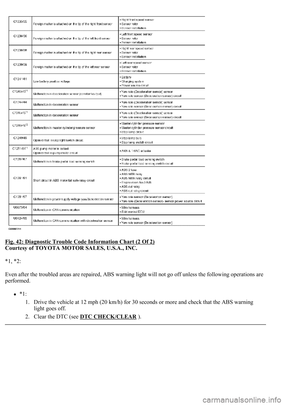
Fig. 42: Diagnostic Trouble Code Information Chart (2 Of 2)
Courtesy of TOYOTA MOTOR SALES, U.S.A., INC.
*1, *2:
Even after the troubled areas are repaired, ABS warning light w<004c004f004f00030051005200570003004a00520003005200490049000300580051004f00480056005600030057004b0048000300490052004f004f0052005a004c0051004a0003005200530048005500440057004c005200510056000300440055004800
03[
performed.
*1:
1. Drive the vehicle at 12 mph (20 km/h) for 30 seconds or more and check that the ABS warning
light goes off.
2. Clear the DTC (see DTC CHECK/CLEAR
).
Page 59 of 4500
*2:
1. Keep the vehicle in the stationary condition for 5 seconds or more and depress the brake pedal
lightly 2 or 3 times.
2. Drive the vehicle at the vehicle speed of 31 mph (50 km/h) and keep depressing the brake pedal
strongly for approximately 3 seconds.
3. Repeat the above operation 3 times or more and check that the ABS warning light goes off.
4. Clear the DTC (see DTC CHECK/CLEAR
).
HINT:
In some cases, the hand-held tester cannot be used when ABS warning light remains on.
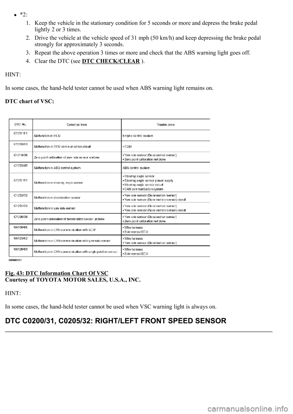
DTC chart of VSC:
Fig. 43: DTC Information Chart Of VSC
Courtesy of TOYOTA MOTOR SALES, U.S.A., INC.
HINT:
In some cases, the hand-held tester cannot be used when VSC warning light is always on.
Page 60 of 4500
CIRCUIT DESCRIPTION
The speed sensor detects wheel speed and sends the appropriate signals to the ECU. These signals are used to
control the ABS control system. The front and rear rotors have 48 serrations respectively.
When the rotors rotate, the magnetic field emitted by the permanent magnet in the speed sensor generates an
AC voltage. Since the frequency of this AC voltage changes in direct proportion to the speed of the rotor, the
frequenc
y is used by the ECU to detect the speed of each wheel.
Trending: relay, Spark plug, Identifying compressor condition, rear seat back assembly, center console, removing v belt tensioner idler pulley, AC Expansion Valve
