LEXUS LS430 2003 Factory Service Manual
Manufacturer: LEXUS, Model Year: 2003,
Model line: LS430,
Model: LEXUS LS430 2003
Pages: 4500, PDF Size: 87.45 MB
LEXUS LS430 2003 Factory Service Manual
LS430 2003
LEXUS
LEXUS
https://www.carmanualsonline.info/img/36/57050/w960_57050-0.png
LEXUS LS430 2003 Factory Service Manual
Trending: intake manifold inlet, c1751, spare tire, fuse box location, instrument cluster, coolant, mirror
Page 41 of 4500
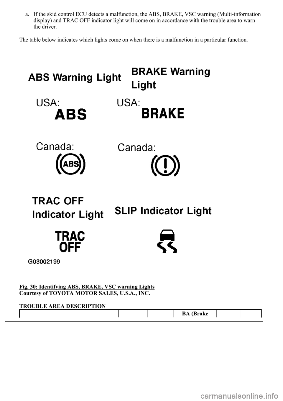
a. If the skid control ECU detects a malfunction, the ABS, BRAKE, VSC warning (Multi-information
display) and TRAC OFF indicator light will come on in accordance with the trouble area to warn
the driver.
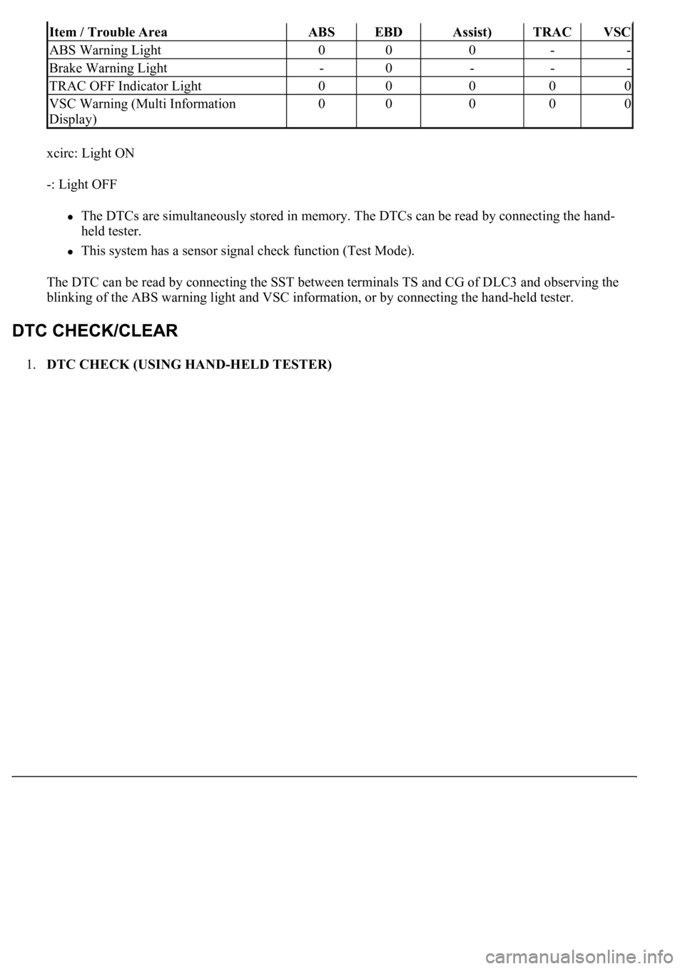
The table below indicates which lights come on when there is a malfunction in a particular function.
Fig. 30: Identifying ABS, BRAKE, VSC warning Lights
Courtesy of TOYOTA MOTOR SALES, U.S.A., INC.
TROUBLE AREA DESCRIPTION
BA (Brake
Page 42 of 4500
xcirc: Light ON
-: Light OFF
The DTCs are simultaneously stored in memory. The DTCs can be read by connecting the hand-
held tester.
This system has a sensor signal check function (Test Mode).
The DTC can be read by connecting the SST between terminals TS and CG of DLC3 and observing the
blinking of the ABS warning light and VSC information, or by connecting the hand-held tester.
1.DTC CHECK (USING HAND-HELD TESTER)
Item / Trouble AreaABSEBDAssist)TRACVSC
ABS Warning Light000--
Brake Warning Light-0---
TRAC OFF Indicator Light00000
VSC Warning (Multi Information
Display)00000
Page 43 of 4500
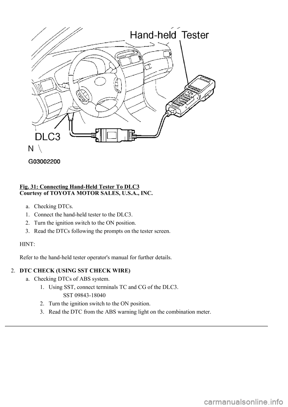
Fig. 31: Connecting Hand-Held Tester To DLC3
Courtesy of TOYOTA MOTOR SALES, U.S.A., INC.
a. Checking DTCs.
1. Connect the hand-held tester to the DLC3.
2. Turn the ignition switch to the ON position.
3. Read the DTCs following the prompts on the tester screen.
HINT:
Refer to the hand-held tester operator's manual for further details.
2.DTC CHECK (USING SST CHECK WIRE)
a. Checking DTCs of ABS system.
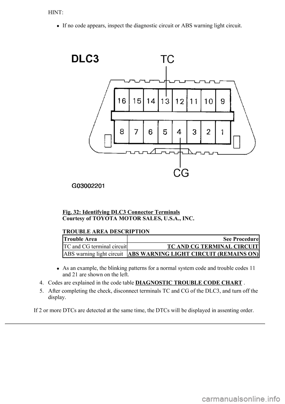
1. Using SST, connect terminals TC and CG of the DLC3.
SST 09843-18040
2. Turn the ignition switch to the ON position.
3. Read the DTC from the ABS warnin
g light on the combination meter.
Page 44 of 4500
HINT:
If no code appears, inspect the diagnostic circuit or ABS warning light circuit.
Fig. 32: Identifying DLC3 Connector Terminals
Courtesy of TOYOTA MOTOR SALES, U.S.A., INC.
TROUBLE AREA DESCRIPTION
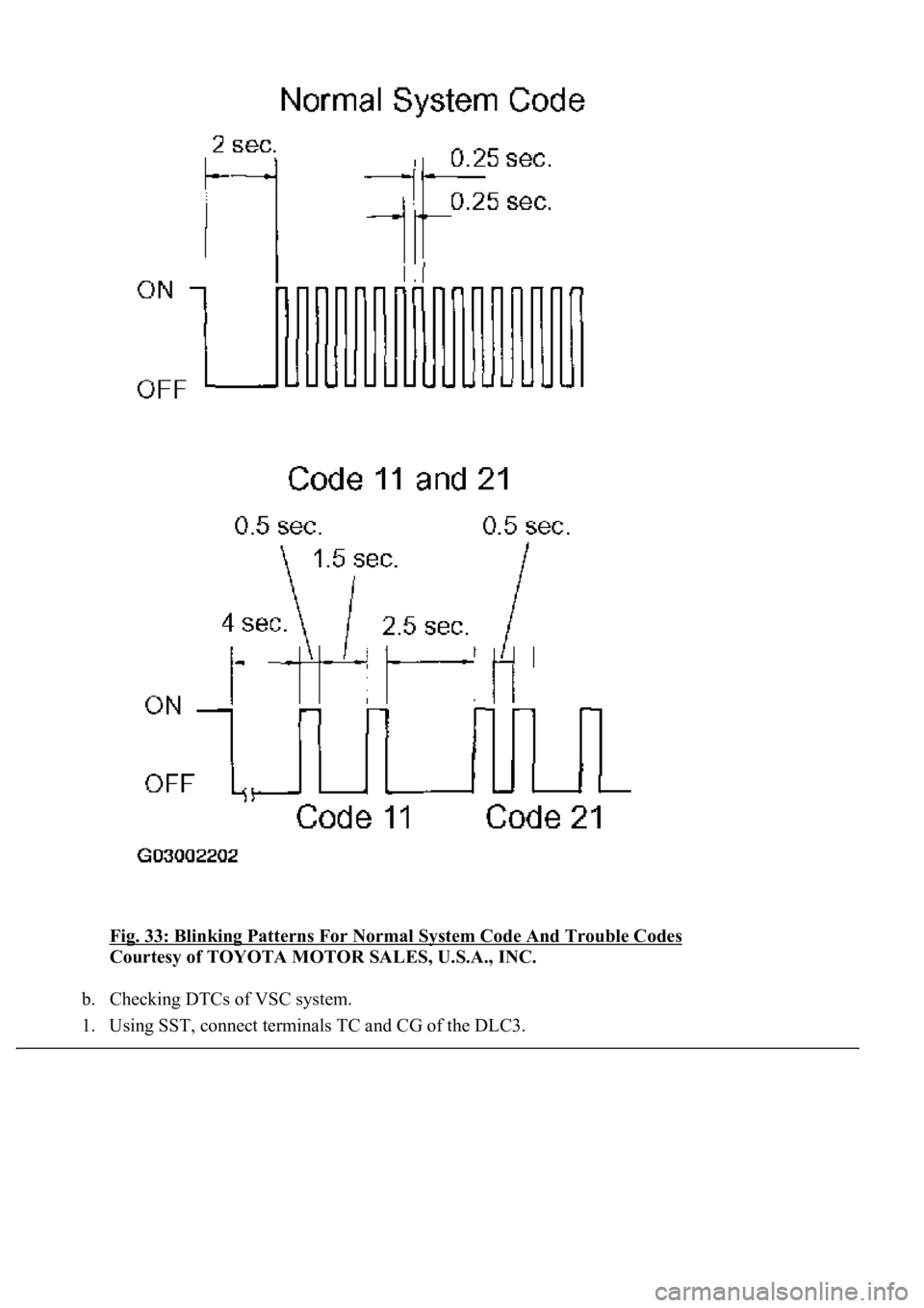
As an example, the blinking patterns for a normal system code and trouble codes 11
and 21 are shown on the left.
4. Codes are explained in the code table DIAGNOSTIC TROUBLE CODE CHART
.
5. After completing the check, disconnect terminals TC and CG of the DLC3, and turn off the
display.
If 2 or more DTCs are detected at the same time, the DTCs will be displayed in assenting order.
Trouble AreaSee Procedure
TC and CG terminal circuitTC AND CG TERMINAL CIRCUIT
ABS warning light circuitABS WARNING LIGHT CIRCUIT (REMAINS ON)
Page 45 of 4500
Fig. 33: Blinking Patterns For Normal System Code And Trouble Codes
Courtesy of TOYOTA MOTOR SALES, U.S.A., INC.
b. Checking DTCs of VSC system.
1. Using SST, connect terminals TC and CG of the DLC3.
Page 46 of 4500
SST 09843-18040
2. Turn the ignition switch to the ON position.
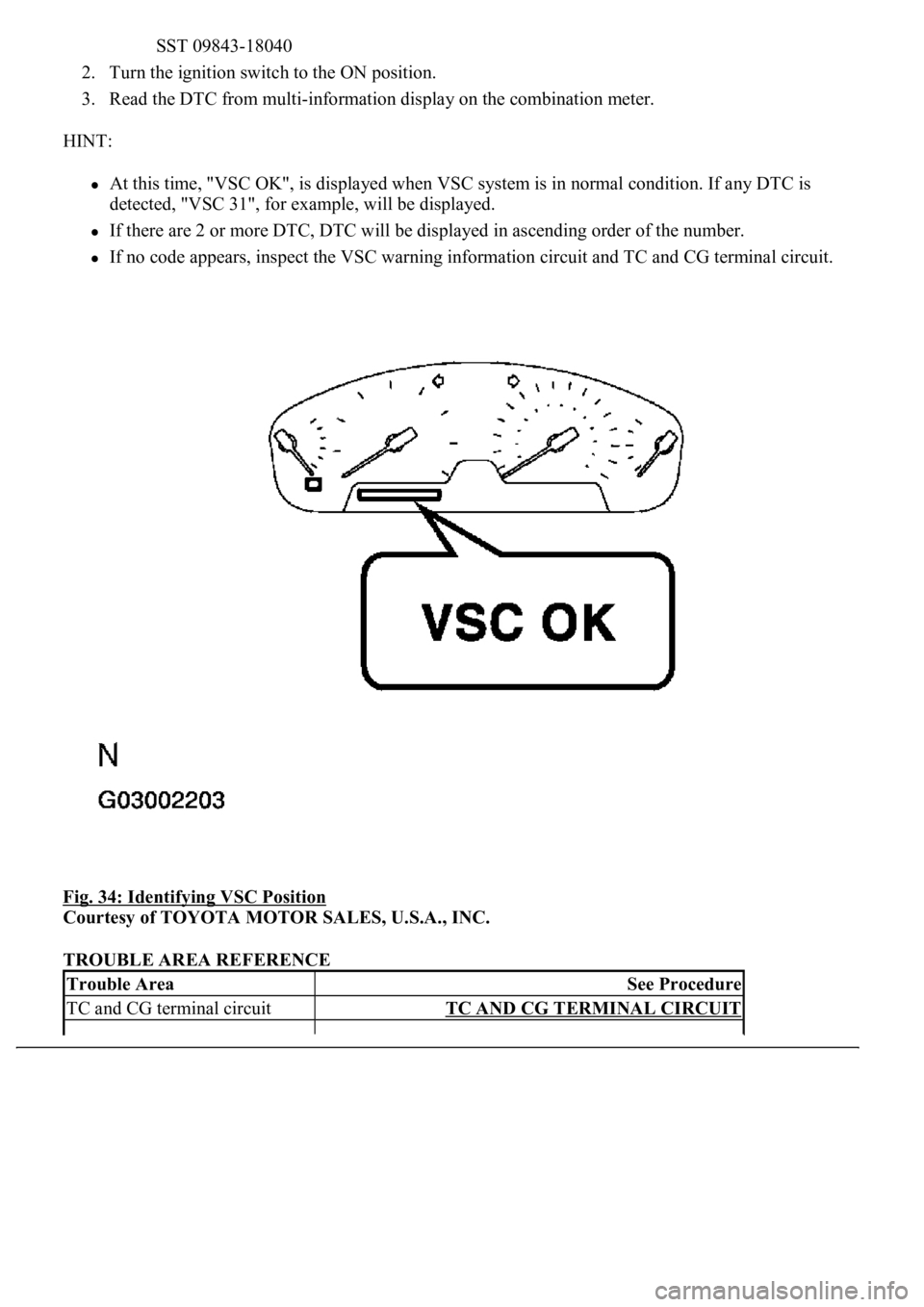
3. Read the DTC from multi-information display on the combination meter.
HINT:
At this time, "VSC OK", is displayed when VSC system is in normal condition. If any DTC is
detected, "VSC 31", for example, will be displayed.
If there are 2 or more DTC, DTC will be displayed in ascending order of the number.
If no code appears, inspect the VSC warning information circuit and TC and CG terminal circuit.
Fig. 34: Identifying VSC Position
Courtesy of TOYOTA MOTOR SALES, U.S.A., INC.
TROUBLE AREA REFERENCE
Trouble AreaSee Procedure
TC and CG terminal circuitTC AND CG TERMINAL CIRCUIT
Page 47 of 4500
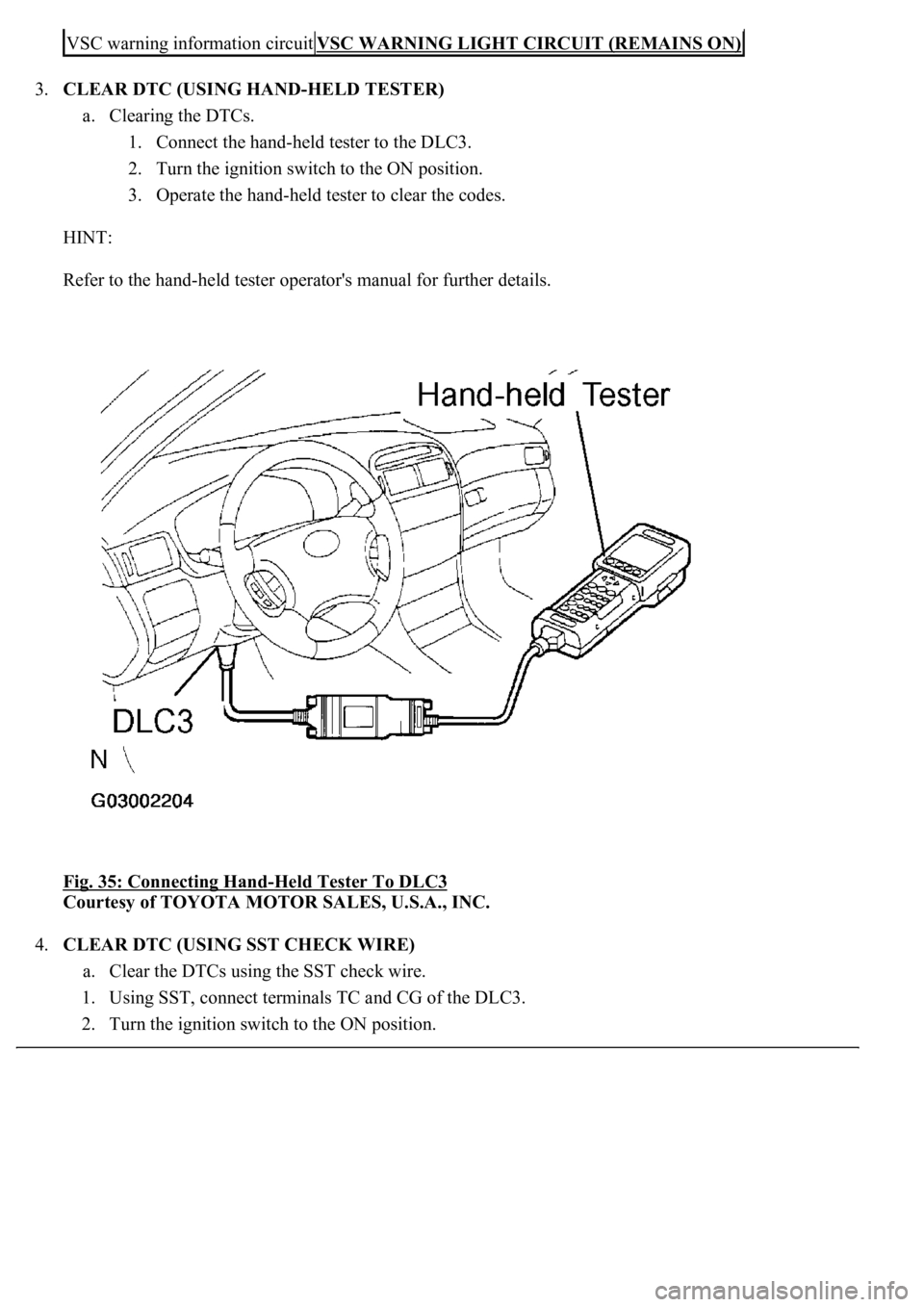
3.CLEAR DTC (USING HAND-HELD TESTER)
a. Clearing the DTCs.
1. Connect the hand-held tester to the DLC3.
2. Turn the ignition switch to the ON position.
3. Operate the hand-held tester to clear the codes.
HINT:
Refer to the hand-held tester operator's manual for further details.
Fig. 35: Connecting Hand
-Held Tester To DLC3
Courtesy of TOYOTA MOTOR SALES, U.S.A., INC.
4.CLEAR DTC (USING SST CHECK WIRE)
a. Clear the DTCs using the SST check wire.
1. Using SST, connect terminals TC and CG of the DLC3.
2. Turn the i
gnition switch to the ON position.
VSC warning information circuitVSC WARNING LIGHT CIRCUIT (REMAINS ON)
Page 48 of 4500
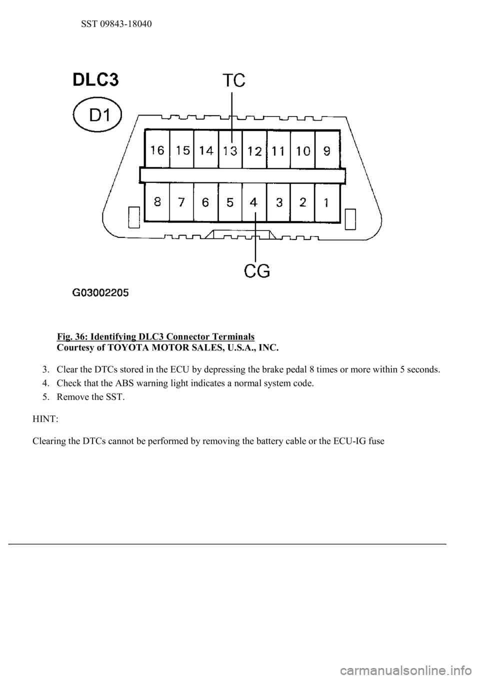
SST 09843-18040
Fig. 36: Identifying DLC3 Connector Terminals
Courtesy of TOYOTA MOTOR SALES, U.S.A., INC.
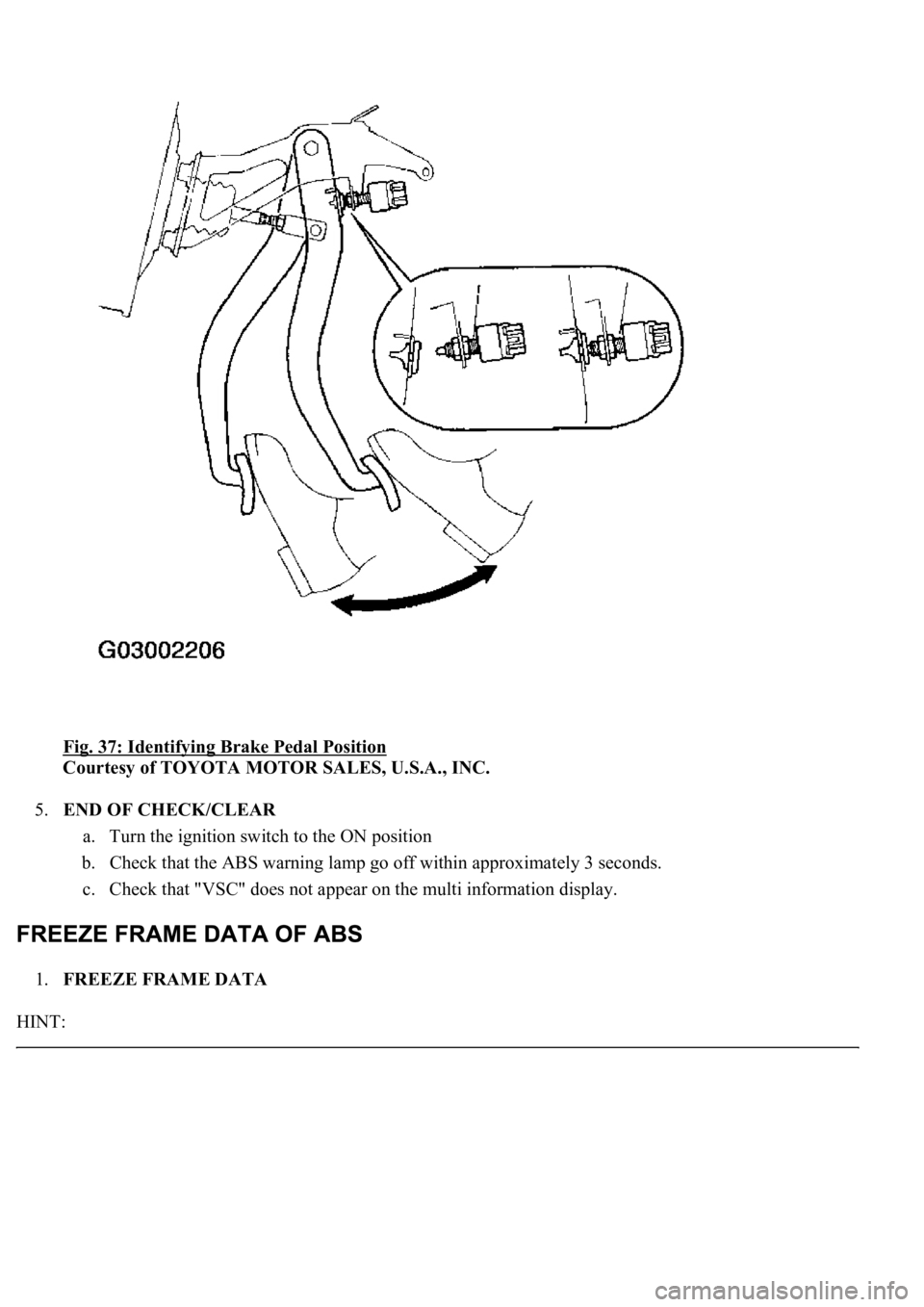
3. Clear the DTCs stored in the ECU by depressing the brake pedal 8 times or more within 5 seconds.
4. Check that the ABS warning light indicates a normal system code.
5. Remove the SST.
HINT:
Clearin
g the DTCs cannot be performed by removing the battery cable or the ECU-IG fuse
Page 49 of 4500
Fig. 37: Identifying Brake Pedal Position
Courtesy of TOYOTA MOTOR SALES, U.S.A., INC.
5.END OF CHECK/CLEAR
a. Turn the ignition switch to the ON position
b. Check that the ABS warning lamp go off within approximately 3 seconds.
c. Check that "VSC" does not appear on the multi information display.
1.FREEZE FRAME DATA
HINT:
Page 50 of 4500
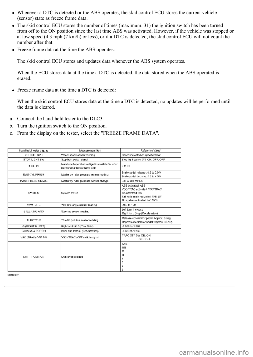
Whenever a DTC is detected or the ABS operates, the skid control ECU stores the current vehicle
(sensor) state as freeze frame data.
The skid control ECU stores the number of times (maximum: 31) the ignition switch has been turned
from off to the ON position since the last time ABS was activated. However, if the vehicle was stopped or
at low speed (4.3 mph (7 km/h) or less), or if a DTC is detected, the skid control ECU will not count the
number after that.
Freeze frame data at the time the ABS operates:
The skid control ECU stores and updates data whenever the ABS system operates.
When the ECU stores data at the time a DTC is detected, the data stored when the ABS operated is
erased.
Freeze frame data at the time a DTC is detected:
When the skid control ECU stores data at the time a DTC is detected, no updates will be performed until
the data is cleared.
a. Connect the hand-held tester to the DLC3.
b. Turn the ignition switch to the ON position.
c. From the display on the tester, select the "FREEZE FRAME DATA".
Trending: heater hose pipe, STARTER, checking oil, stop start, low oil pressure, air suspension, diagram
