LEXUS LS430 2003 Factory Repair Manual
Manufacturer: LEXUS, Model Year: 2003,
Model line: LS430,
Model: LEXUS LS430 2003
Pages: 4500, PDF Size: 87.45 MB
LEXUS LS430 2003 Factory Repair Manual
LS430 2003
LEXUS
LEXUS
https://www.carmanualsonline.info/img/36/57050/w960_57050-0.png
LEXUS LS430 2003 Factory Repair Manual
Trending: Sp2, B2402, mileage, air filter, steering wheel adjustment, zero point calibration, seats
Page 391 of 4500
Air flow temperature changes in accordance with each display code.
NG: REPLACE AIR CONDITIONING AMPLIFIER (SEE REPLACEMENT
)
OK: Go to next step
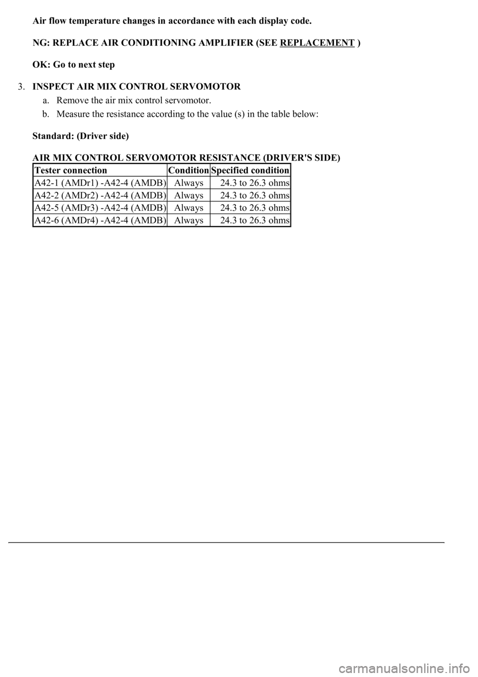
3.INSPECT AIR MIX CONTROL SERVOMOTOR
a. Remove the air mix control servomotor.
b. Measure the resistance according to the value (s) in the table below:
Standard: (Driver side)
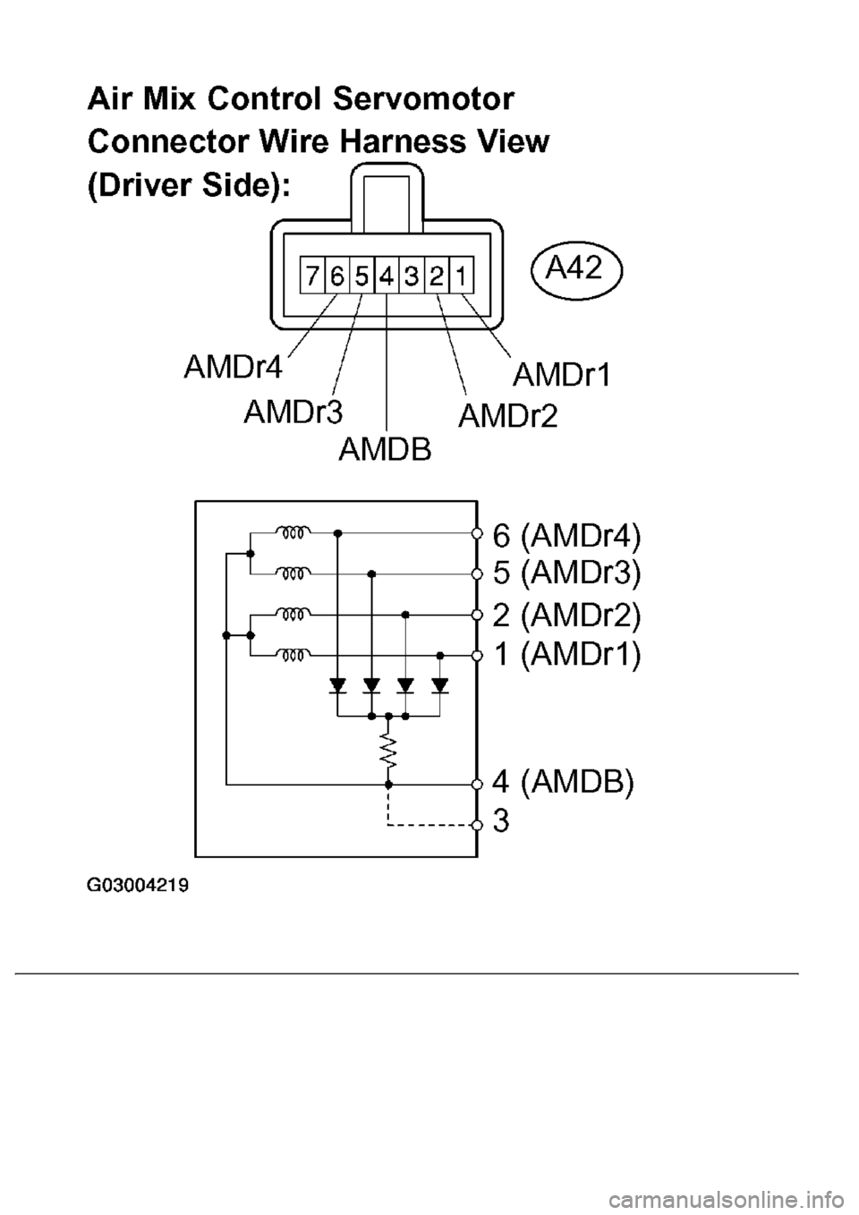
AIR MIX CONTROL SERVOMOTOR RESISTANCE (DRIVER'S SIDE)
Tester connectionConditionSpecified condition
A42-1 (AMDr1) -A42-4 (AMDB)Always24.3 to 26.3 ohms
A42-2 (AMDr2) -A42-4 (AMDB)Always24.3 to 26.3 ohms
A42-5 (AMDr3) -A42-4 (AMDB)Always24.3 to 26.3 ohms
A42-6 (AMDr4) -A42-4 (AMDB)Always24.3 to 26.3 ohms
Page 392 of 4500
Page 393 of 4500
Fig. 142: Inspecting Air Mix Control Servomotor (Driver'S Side)
Courtesy of TOYOTA MOTOR SALES, U.S.A., INC.
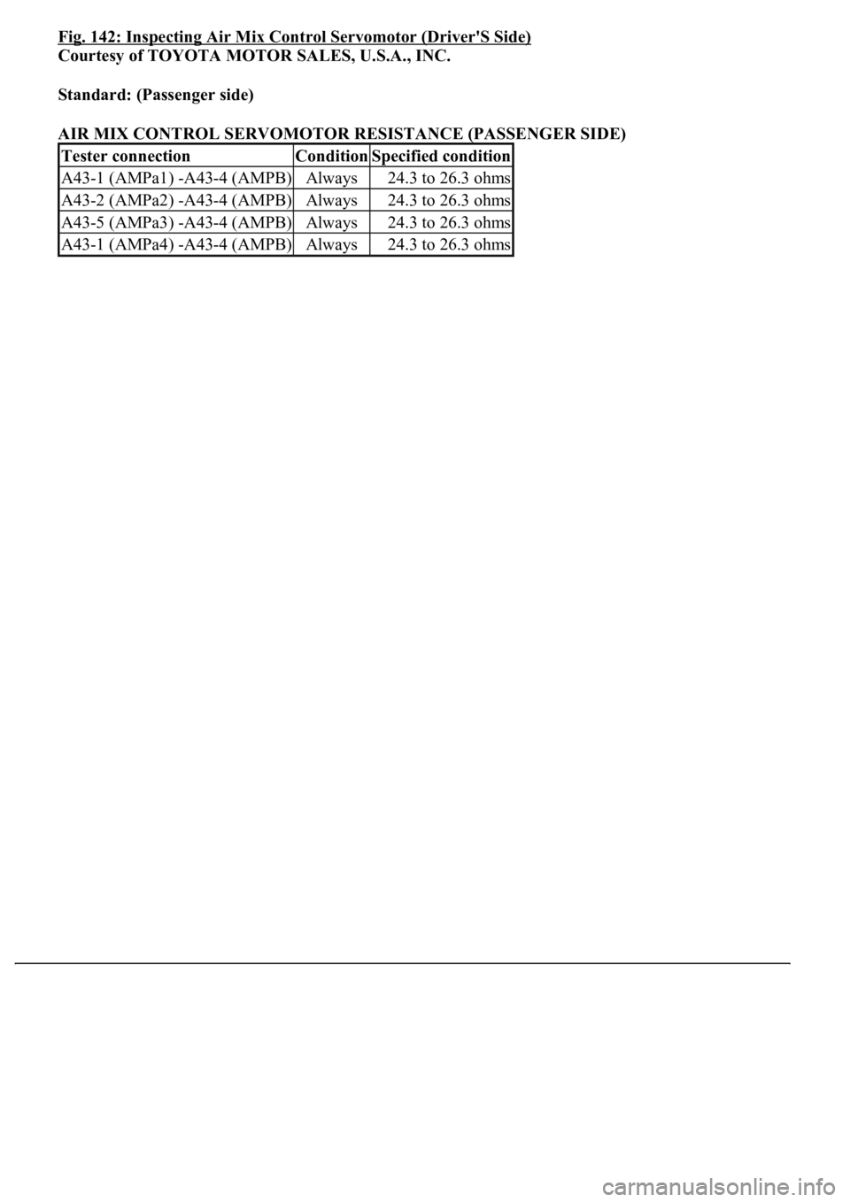
Standard: (Passenger side)
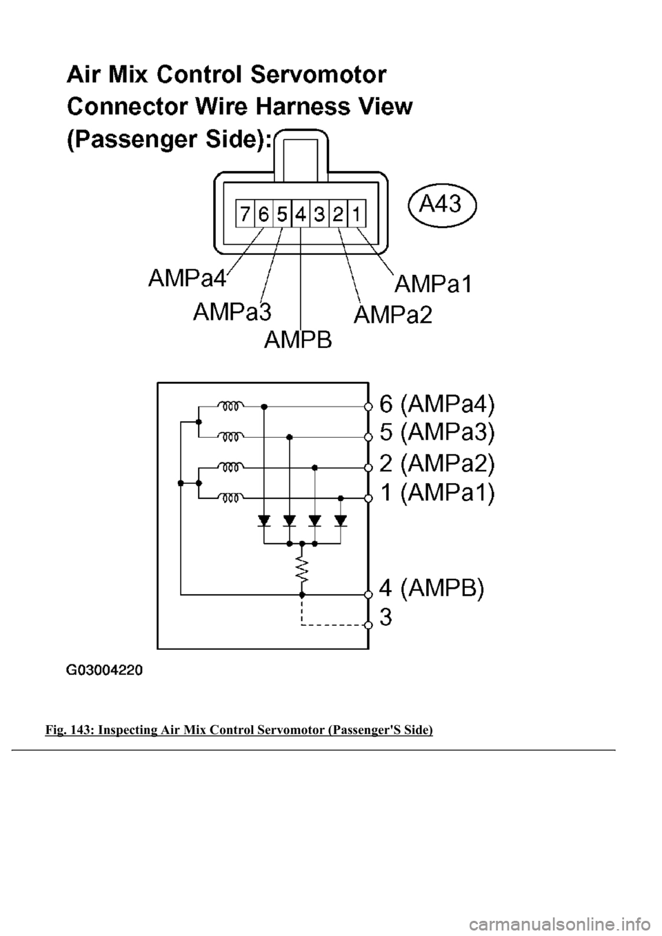
AIR MIX CONTROL SERVOMOTOR RESISTANCE (PASSENGER SIDE)
Tester connectionConditionSpecified condition
A43-1 (AMPa1) -A43-4 (AMPB)Always24.3 to 26.3 ohms
A43-2 (AMPa2) -A43-4 (AMPB)Always24.3 to 26.3 ohms
A43-5 (AMPa3) -A43-4 (AMPB)Always24.3 to 26.3 ohms
A43-1 (AMPa4) -A43-4 (AMPB)Always24.3 to 26.3 ohms
Page 394 of 4500
Fig. 143: Inspecting Air Mix Control Servomotor (Passenger'S Side)
Page 395 of 4500
Courtesy of TOYOTA MOTOR SALES, U.S.A., INC.
NG: REPLACE AIR MIX CONTROL SERVOMOTOR
OK: Go to next step
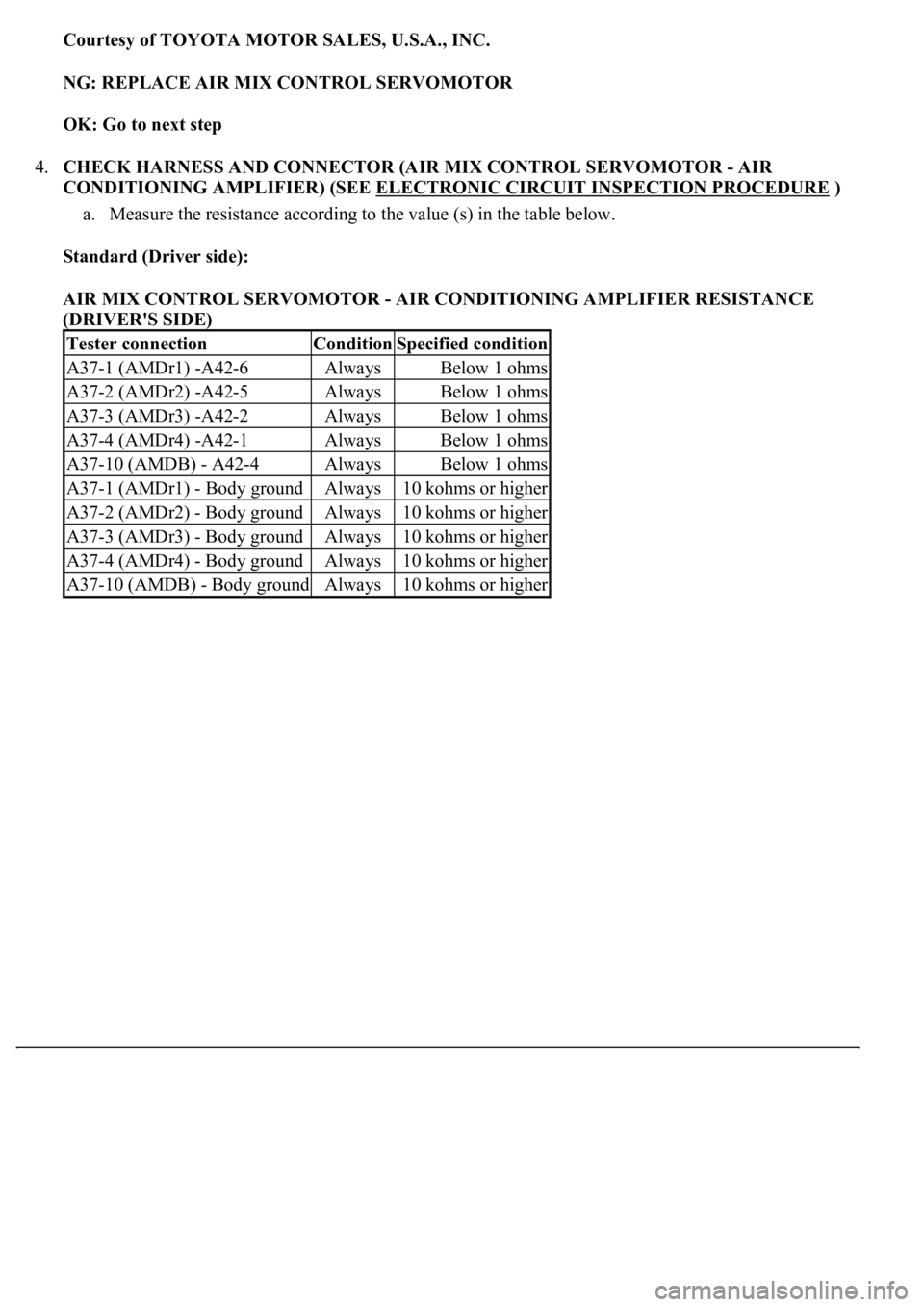
4.CHECK HARNESS AND CONNECTOR (AIR MIX CONTROL SERVOMOTOR - AIR
CONDITIONING AMPLIFIER) (SEE ELECTRONIC CIRCUIT INSPECTION PROCEDURE
)
a. Measure the resistance according to the value (s) in the table below.
Standard (Driver side):
AIR MIX CONTROL SERVOMOTOR - AIR CONDITIONING AMPLIFIER RESISTANCE
(DRIVER'S SIDE)
Tester connectionConditionSpecified condition
A37-1 (AMDr1) -A42-6AlwaysBelow 1 ohms
A37-2 (AMDr2) -A42-5AlwaysBelow 1 ohms
A37-3 (AMDr3) -A42-2AlwaysBelow 1 ohms
A37-4 (AMDr4) -A42-1AlwaysBelow 1 ohms
A37-10 (AMDB) - A42-4AlwaysBelow 1 ohms
A37-1 (AMDr1) - Body groundAlways10 kohms or higher
A37-2 (AMDr2) - Body groundAlways10 kohms or higher
A37-3 (AMDr3) - Body groundAlways10 kohms or higher
A37-4 (AMDr4) - Body groundAlways10 kohms or higher
A37-10 (AMDB) - Body groundAlways10 kohms or higher
Page 396 of 4500
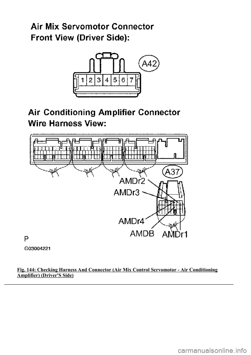
Fig. 144: Checking Harness And Connector (Air Mix Control Servomotor - Air Conditioning
Amplifier) (Driver'S Side)
Page 397 of 4500
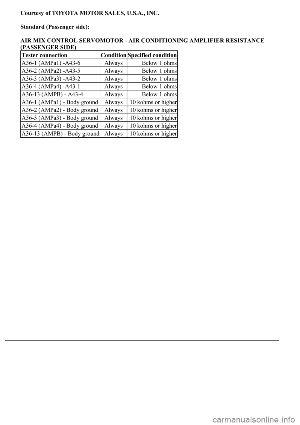
Courtesy of TOYOTA MOTOR SALES, U.S.A., INC.
Standard (Passenger side):
AIR MIX CONTROL SERVOMOTOR - AIR CONDITIONING AMPLIFIER RESISTANCE
(PASSENGER SIDE)
Tester connectionConditionSpecified condition
A36-1 (AMPa1) -A43-6AlwaysBelow 1 ohms
A36-2 (AMPa2) -A43-5AlwaysBelow 1 ohms
A36-3 (AMPa3) -A43-2AlwaysBelow 1 ohms
A36-4 (AMPa4) -A43-1AlwaysBelow 1 ohms
A36-13 (AMPB) - A43-4AlwaysBelow 1 ohms
A36-1 (AMPa1) - Body groundAlways10 kohms or higher
A36-2 (AMPa2) - Body groundAlways10 kohms or higher
A36-3 (AMPa3) - Body groundAlways10 kohms or higher
A36-4 (AMPa4) - Body groundAlways10 kohms or higher
A36-13 (AMPB) - Body groundAlways10 kohms or higher
Page 398 of 4500
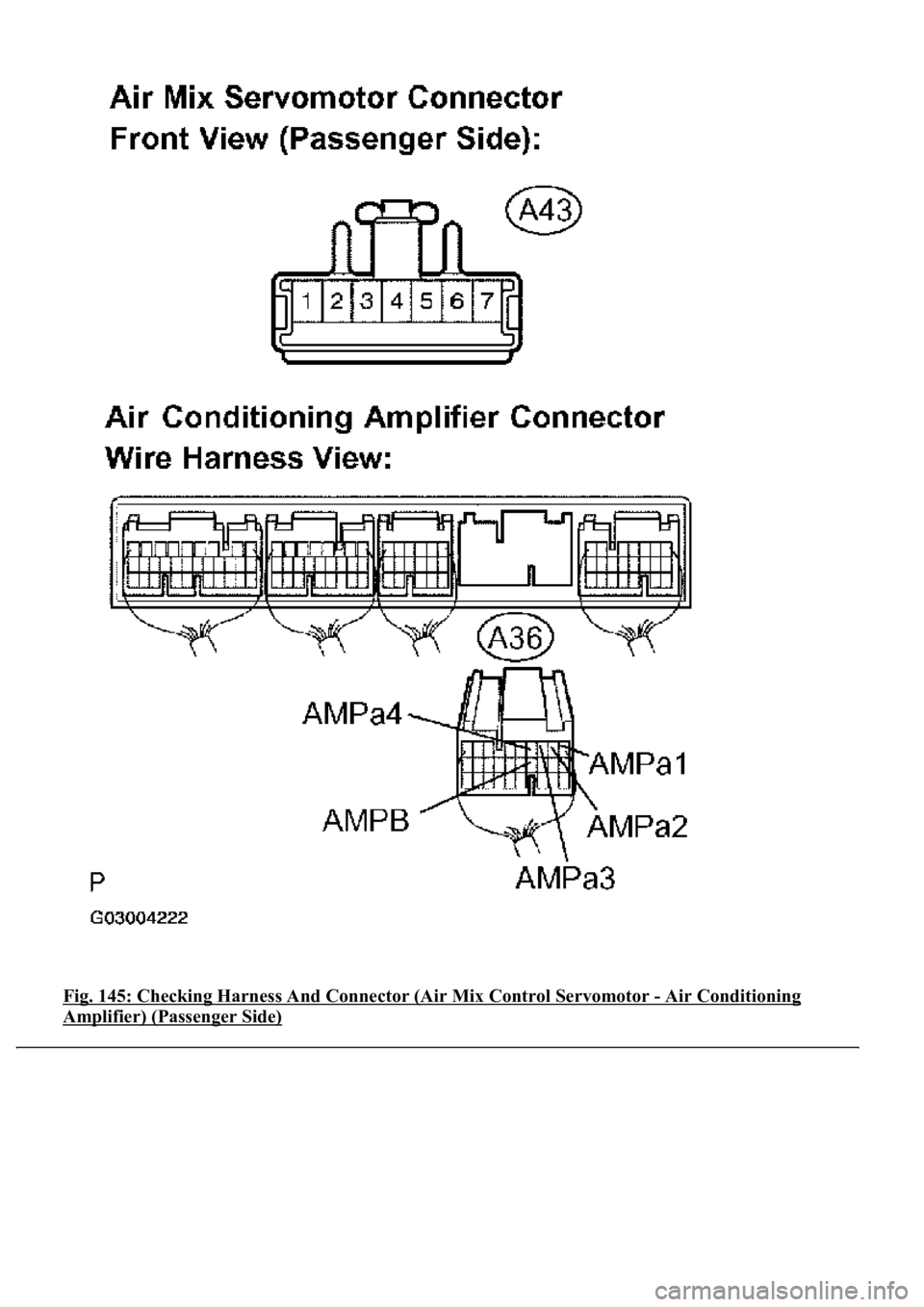
Fig. 145: Checking Harness And Connector (Air Mix Control Servomotor - Air Conditioning
Amplifier) (Passenger Side)
Page 399 of 4500
Courtesy of TOYOTA MOTOR SALES, U.S.A., INC.
NG: REPAIR OR REPLACE HARNESS OR / CONNECTOR
OK: REPLACE AIR CONDITIONING AMPLIFIER (SEE REPLACEMENT
)
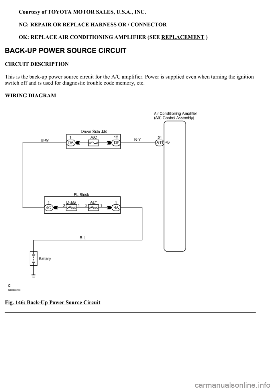
CIRCUIT DESCRIPTION
This is the back-up power source circuit for the A/C amplifier. Power is supplied even when turning the ignition
switch off and is used for diagnostic trouble code memory, etc.
WIRING DIAGRAM
Fig. 146: Back
-Up Power Source Circuit
Page 400 of 4500
Courtesy of TOYOTA MOTOR SALES, U.S.A., INC.
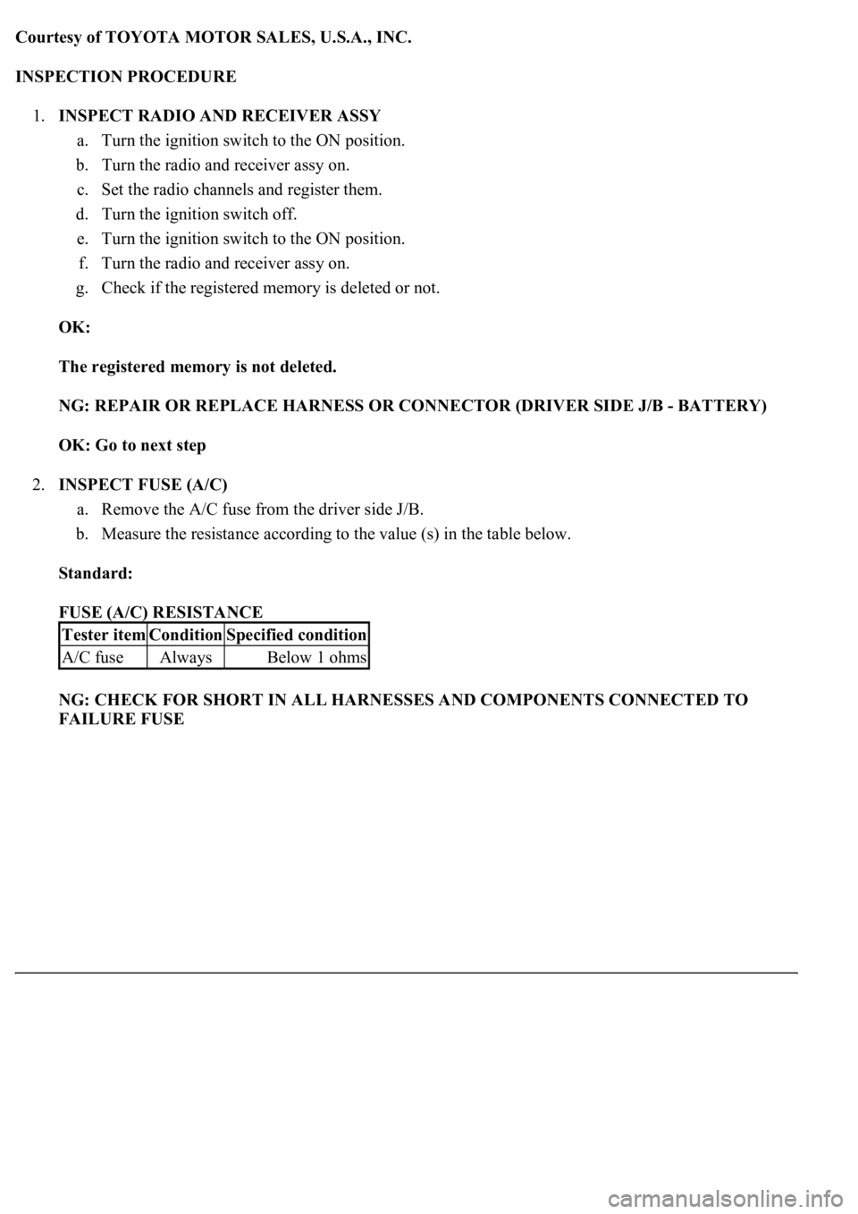
INSPECTION PROCEDURE
1.INSPECT RADIO AND RECEIVER ASSY
a. Turn the ignition switch to the ON position.
b. Turn the radio and receiver assy on.
c. Set the radio channels and register them.
d. Turn the ignition switch off.
e. Turn the ignition switch to the ON position.
f. Turn the radio and receiver assy on.
g. Check if the registered memory is deleted or not.
OK:
The registered memory is not deleted.
NG: REPAIR OR REPLACE HARNESS OR CONNECTOR (DRIVER SIDE J/B - BATTERY)
OK: Go to next step
2.INSPECT FUSE (A/C)
a. Remove the A/C fuse from the driver side J/B.
b. Measure the resistance according to the value (s) in the table below.
Standard:
FUSE (A/C) RESISTANCE
NG: CHECK FOR SHORT IN ALL HARNESSES AND COMPONENTS CONNECTED TO
FAILURE FUSE
Tester itemConditionSpecified condition
A/C fuseAlwaysBelow 1 ohms
Trending: removing v belt tensioner, change wheel, sat nav, Conditioner, coolant level, injection, AUX
