LEXUS LS430 2003 Factory Repair Manual
Manufacturer: LEXUS, Model Year: 2003,
Model line: LS430,
Model: LEXUS LS430 2003
Pages: 4500, PDF Size: 87.45 MB
LEXUS LS430 2003 Factory Repair Manual
LS430 2003
LEXUS
LEXUS
https://www.carmanualsonline.info/img/36/57050/w960_57050-0.png
LEXUS LS430 2003 Factory Repair Manual
Trending: drain bolt, wheel, hood release, park assist, Identifying condition, removing v belt tensioner idler pulley, lock
Page 381 of 4500
Page 382 of 4500
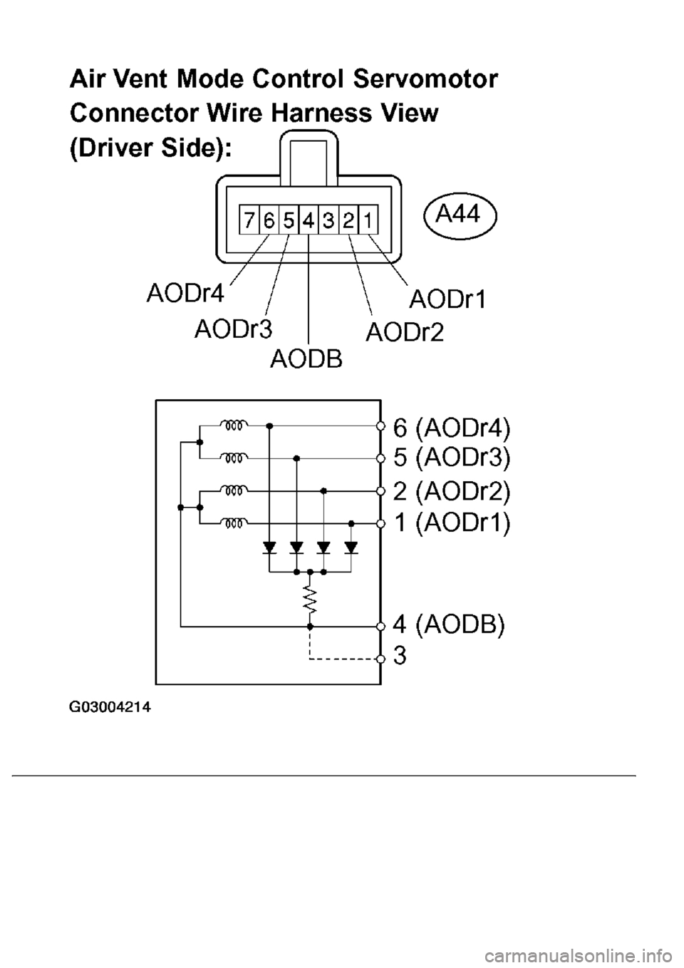
Fig. 137: Inspecting Air Vent Mode Control Servomotor (Driver'S Side)
Courtesy of TOYOTA MOTOR SALES, U.S.A., INC.
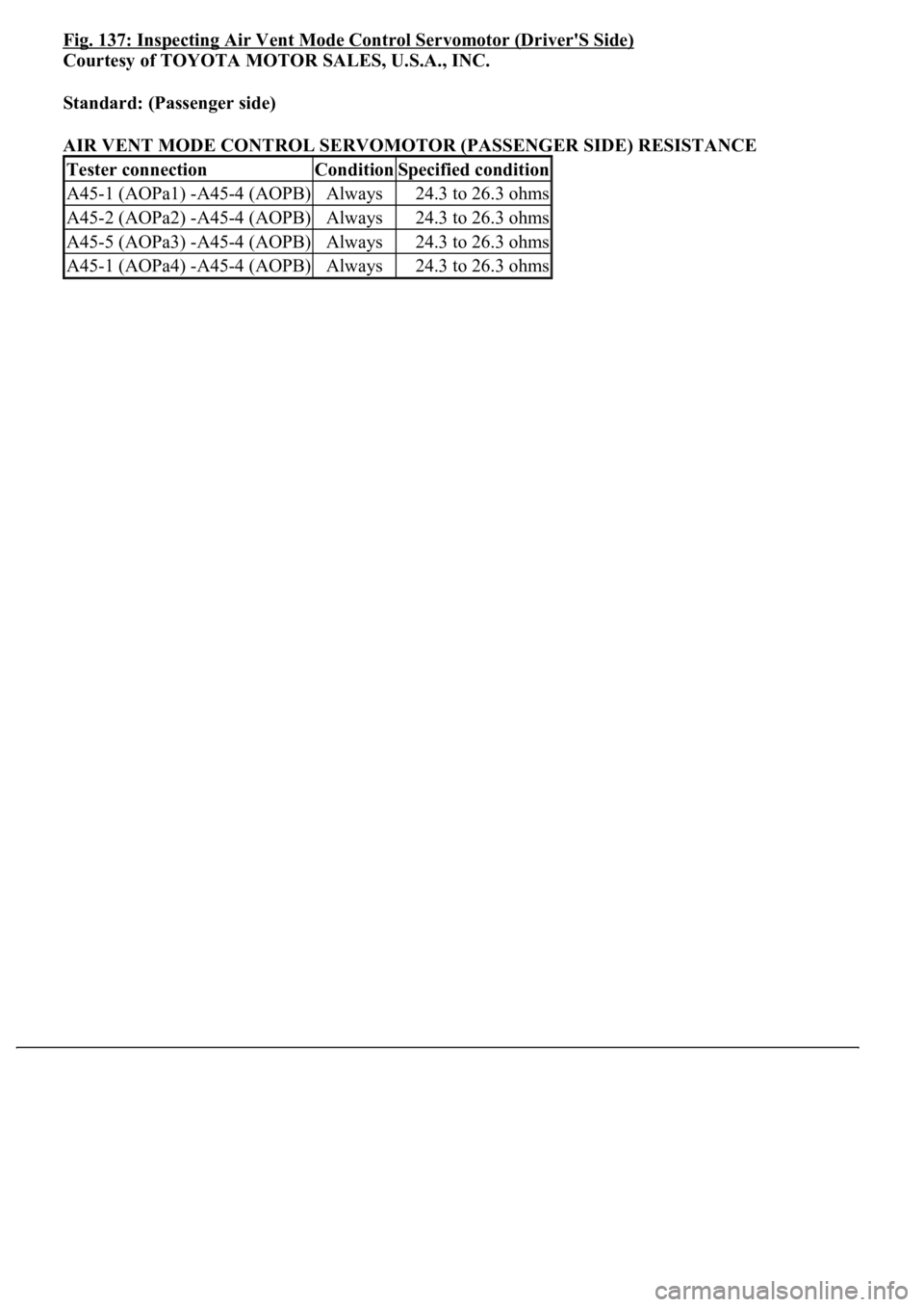
Standard: (Passenger side)
AIR VENT MODE CONTROL SERVOMOTOR (PASSENGER SIDE) RESISTANCE
Tester connectionConditionSpecified condition
A45-1 (AOPa1) -A45-4 (AOPB)Always24.3 to 26.3 ohms
A45-2 (AOPa2) -A45-4 (AOPB)Always24.3 to 26.3 ohms
A45-5 (AOPa3) -A45-4 (AOPB)Always24.3 to 26.3 ohms
A45-1 (AOPa4) -A45-4 (AOPB)Always24.3 to 26.3 ohms
Page 383 of 4500
Fig. 138: Inspecting Air Vent Mode Control Servomotor (Passenger'S Side)
Page 384 of 4500
Courtesy of TOYOTA MOTOR SALES, U.S.A., INC.
NG: REPLACE AIR OUTLET SERVOMOTOR
OK: Go to next step
3.CHECK HARNESS AND CONNECTOR (AIR OUTLET SERVOMOTOR - AIR
CONDITIONING AMPLIFIER) (SEE ELECTRONIC CIRCUIT INSPECTION PROCEDURE
)
a. Measure the resistance according to the value (s) in the table below.
Standard (Driver side):
AIR OUTLET SERVOMOTOR - AIR CONDITIONING AMPLIFIER RESISTANCE (DRIVER'S
SIDE)
Tester connectionConditionSpecified condition
A37-5 (AODr) -A44-6AlwaysBelow 1 ohms
A37-6 (AODr2) -A44-5AlwaysBelow 1 ohms
A37-12 (AODr3) -A44-2AlwaysBelow 1 ohms
A37-13 (AODr4) -A44-1AlwaysBelow 1 ohms
A37-22 (AODB) - A44-4AlwaysBelow 1 ohms
A37-5 (AODr1) - Body groundAlways10 kohms or higher
A37-6 (AODr2) - Body groundAlways10 kohms or higher
A37-12 (AODr3) - Body groundAlways10 kohms or higher
A37-13 (AODr4) - Body groundAlways10 kohms or higher
A37-22 (AODB) - Body groundAlways10 kohms or higher
Page 385 of 4500
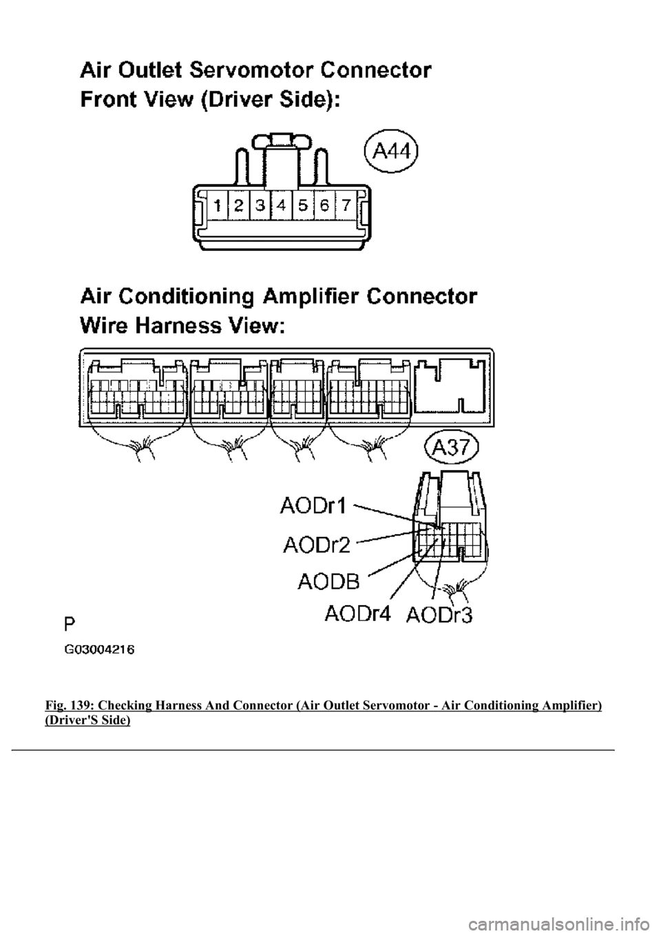
Fig. 139: Checking Harness And Connector (Air Outlet Servomotor - Air Conditioning Amplifier)
(Driver'S Side)
Page 386 of 4500
Courtesy of TOYOTA MOTOR SALES, U.S.A., INC.
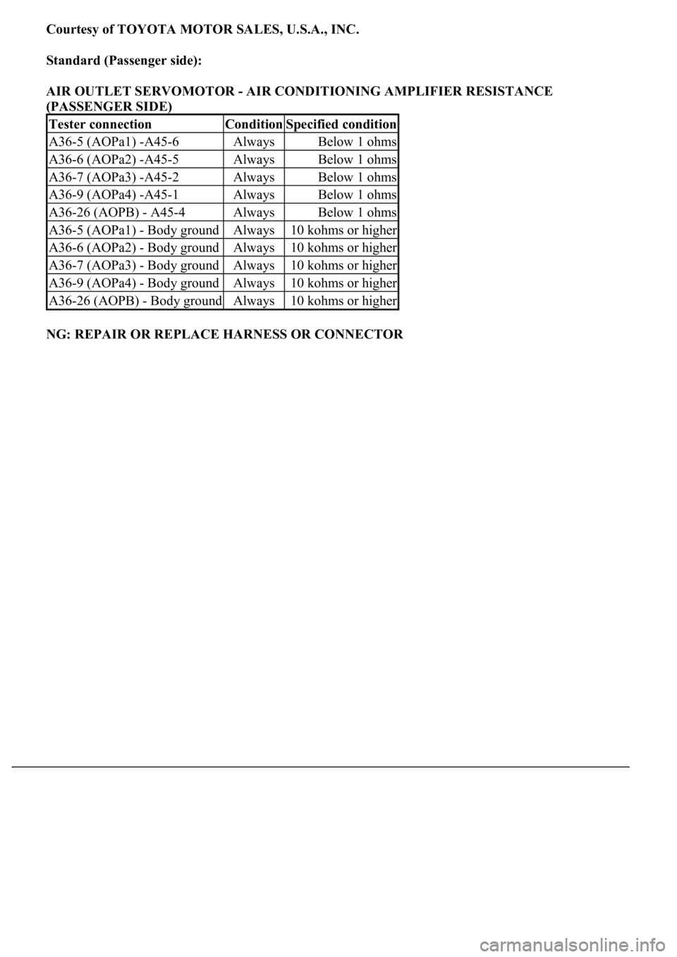
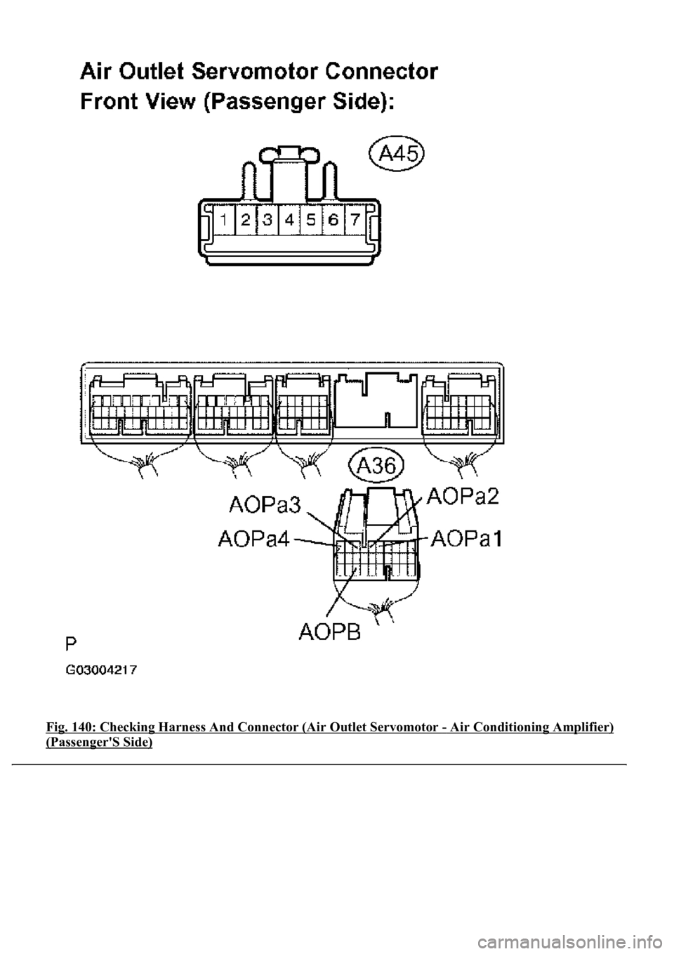
Standard (Passenger side):
AIR OUTLET SERVOMOTOR - AIR CONDITIONING AMPLIFIER RESISTANCE
(PASSENGER SIDE)
NG: REPAIR OR REPLACE HARNESS OR CONNECTOR
Tester connectionConditionSpecified condition
A36-5 (AOPa1) -A45-6AlwaysBelow 1 ohms
A36-6 (AOPa2) -A45-5AlwaysBelow 1 ohms
A36-7 (AOPa3) -A45-2AlwaysBelow 1 ohms
A36-9 (AOPa4) -A45-1AlwaysBelow 1 ohms
A36-26 (AOPB) - A45-4AlwaysBelow 1 ohms
A36-5 (AOPa1) - Body groundAlways10 kohms or higher
A36-6 (AOPa2) - Body groundAlways10 kohms or higher
A36-7 (AOPa3) - Body groundAlways10 kohms or higher
A36-9 (AOPa4) - Body groundAlways10 kohms or higher
A36-26 (AOPB) - Body groundAlways10 kohms or higher
Page 387 of 4500
Fig. 140: Checking Harness And Connector (Air Outlet Servomotor - Air Conditioning Amplifier)
(Passenger'S Side)
Page 388 of 4500
Courtesy of TOYOTA MOTOR SALES, U.S.A., INC.
OK: REPLACE AIR CONDITIONING AMPLIFIER (SEE REPLACEMENT
)
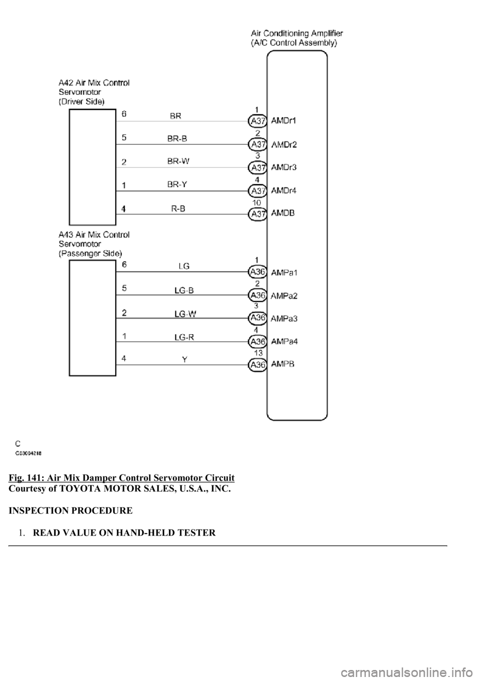
CIRCUIT DESCRIPTION
This servomotor is controlled by the A/C amplifier. Air flow temperature changes when moving the air mix
damper to the target point. The target point can be detected with the air mix damper position sensor.
WIRING DIAGRAM
Page 389 of 4500
Fig. 141: Air Mix Damper Control Servomotor Circuit
Courtesy of TOYOTA MOTOR SALES, U.S.A., INC.
INSPECTION PROCEDURE
1.READ VALUE ON HAND-HELD TESTER
Page 390 of 4500
a. Connect the hand-held tester to the DLC3.
b. Turn the ignition switch to the ON position and push the hand-held tester main switch on.
c. Select the item below in the DATA LIST, and read the display on the hand-held tester.
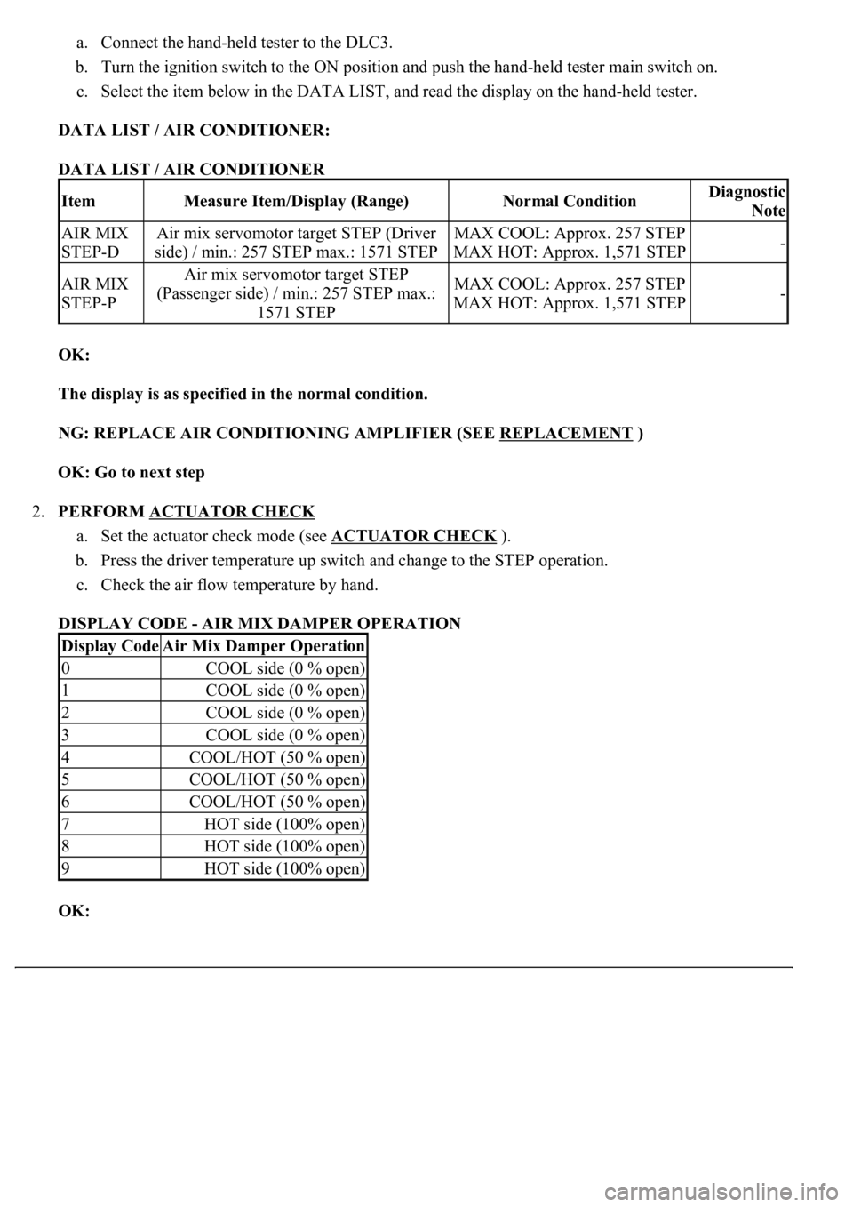
DATA LIST / AIR CONDITIONER:
DATA LIST / AIR CONDITIONER
OK:
The display is as specified in the normal condition.
NG: REPLACE AIR CONDITIONING AMPLIFIER (SEE REPLACEMENT
)
OK: Go to next step
2.PERFORM ACTUATOR CHECK
a. Set the actuator check mode (see ACTUATOR CHECK
).
b. Press the driver temperature up switch and change to the STEP operation.
c. Check the air flow temperature by hand.
DISPLAY CODE - AIR MIX DAMPER OPERATION
OK:
ItemMeasure Item/Display (Range)Normal ConditionDiagnostic
Note
AIR MIX
STEP-DAir mix servomotor target STEP (Driver
side) / min.: 257 STEP max.: 1571 STEPMAX COOL: Approx. 257 STEP
MAX HOT: Approx. 1,571 STEP-
AIR MIX
STEP-PAir mix servomotor target STEP
(Passenger side) / min.: 257 STEP max.:
1571 STEPMAX COOL: Approx. 257 STEP
MAX HOT: Approx. 1,571 STEP-
Display CodeAir Mix Damper Operation
0COOL side (0 % open)
1COOL side (0 % open)
2COOL side (0 % open)
3COOL side (0 % open)
4COOL/HOT (50 % open)
5COOL/HOT (50 % open)
6COOL/HOT (50 % open)
7HOT side (100% open)
8HOT side (100% open)
9HOT side (100% open)
Trending: alternator, air condition, Compressor control valve, brake sensor, exhaust manifold, catalytic converter, tow bar
