LEXUS LS430 2003 Factory Repair Manual
Manufacturer: LEXUS, Model Year: 2003,
Model line: LS430,
Model: LEXUS LS430 2003
Pages: 4500, PDF Size: 87.45 MB
LEXUS LS430 2003 Factory Repair Manual
LS430 2003
LEXUS
LEXUS
https://www.carmanualsonline.info/img/36/57050/w960_57050-0.png
LEXUS LS430 2003 Factory Repair Manual
Trending: low beam, check transmission fluid, fog light, ground clearance, belt, injection, set clock
Page 401 of 4500
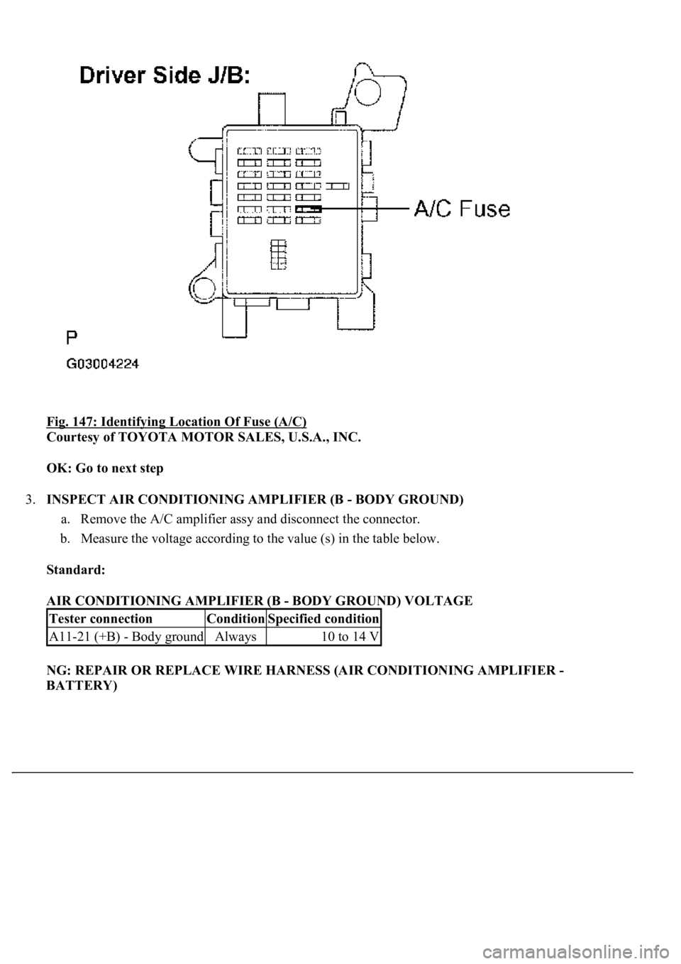
Fig. 147: Identifying Location Of Fuse (A/C)
Courtesy of TOYOTA MOTOR SALES, U.S.A., INC.
OK: Go to next step
3.INSPECT AIR CONDITIONING AMPLIFIER (B - BODY GROUND)
a. Remove the A/C amplifier assy and disconnect the connector.
b. Measure the voltage according to the value (s) in the table below.
Standard:
AIR CONDITIONING AMPLIFIER (B - BODY GROUND) VOLTAGE
NG: REPAIR OR REPLACE WIRE HARNESS (AIR CONDITIONING AMPLIFIER -
BATTERY)
Tester connectionConditionSpecified condition
A11-21 (+B) - Body groundAlways10 to 14 V
Page 402 of 4500
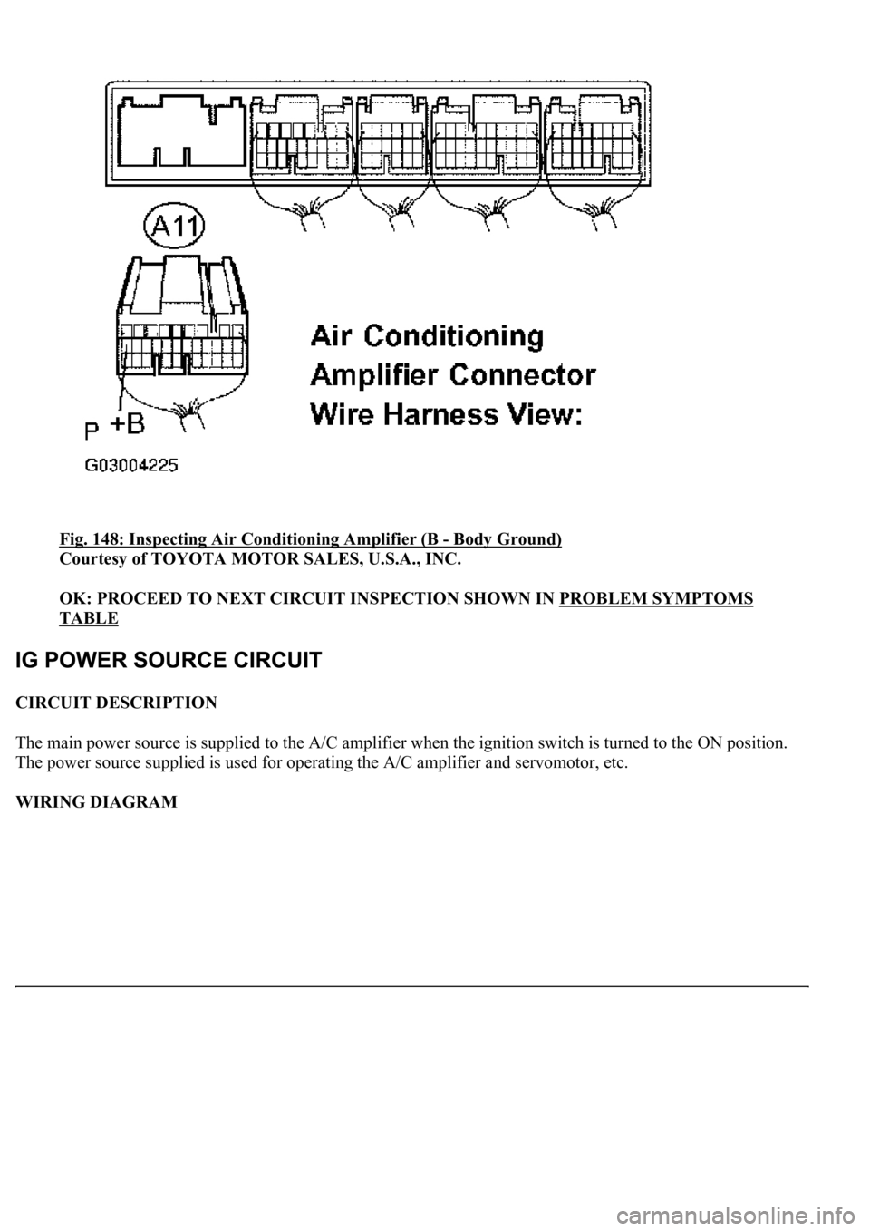
Fig. 148: Inspecting Air Conditioning Amplifier (B - Body Ground)
Courtesy of TOYOTA MOTOR SALES, U.S.A., INC.
OK: PROCEED TO NEXT CIRCUIT INSPECTION SHOWN IN PROBLEM SYMPTOMS
TABLE
CIRCUIT DESCRIPTION
The main power source is supplied to the A/C amplifier when the ignition switch is turned to the ON position.
The power source supplied is used for operating the A/C amplifier and servomotor, etc.
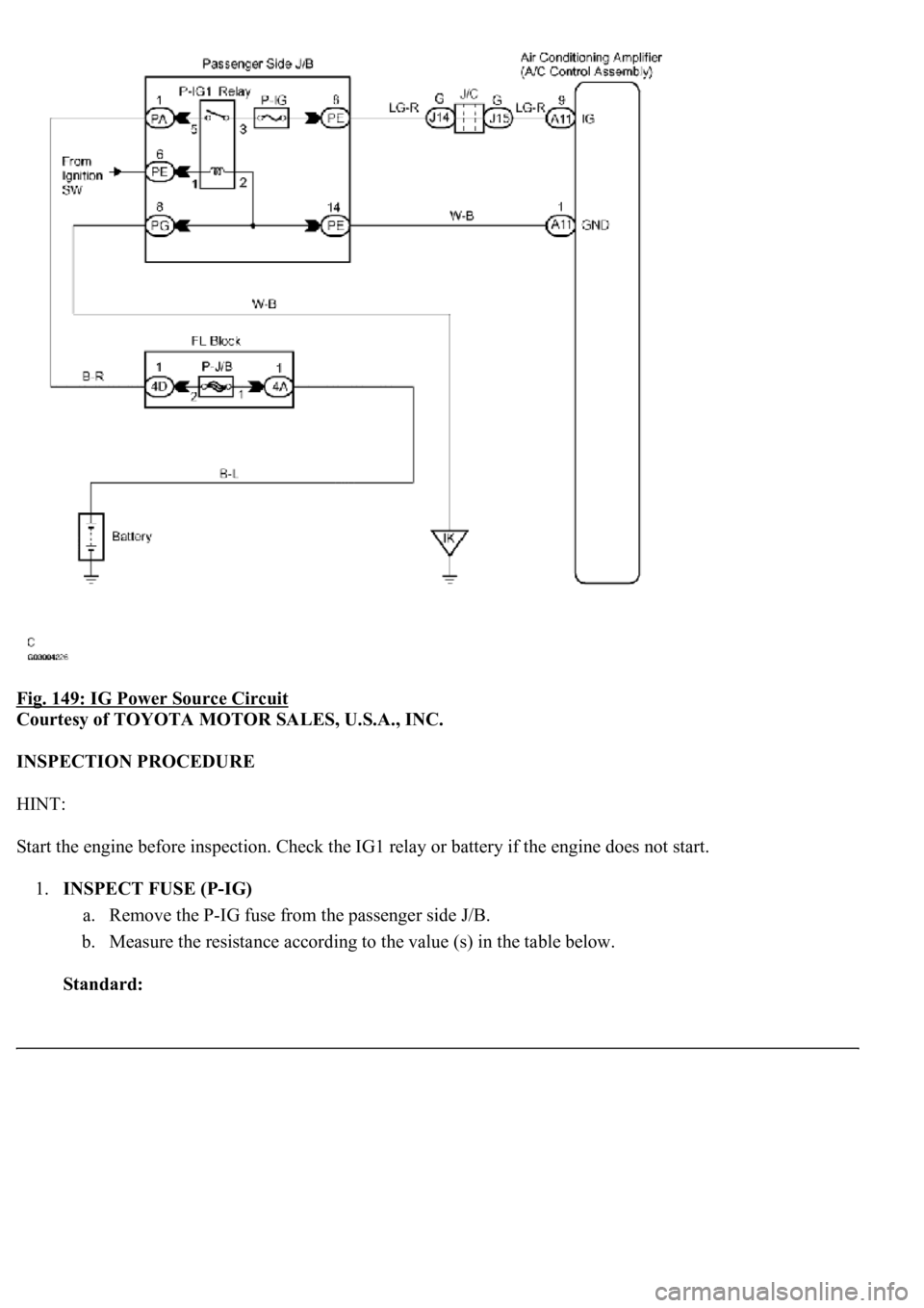
WIRING DIAGRAM
Page 403 of 4500
Fig. 149: IG Power Source Circuit
Courtesy of TOYOTA MOTOR SALES, U.S.A., INC.
INSPECTION PROCEDURE
HINT:
Start the engine before inspection. Check the IG1 relay or battery if the engine does not start.
1.INSPECT FUSE (P-IG)
a. Remove the P-IG fuse from the passenger side J/B.
b. Measure the resistance according to the value (s) in the table below.
Standard:
Page 404 of 4500
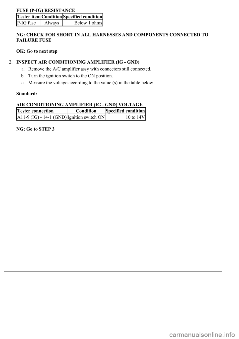
FUSE (P-IG) RESISTANCE
NG: CHECK FOR SHORT IN ALL HARNESSES AND COMPONENTS CONNECTED TO
FAILURE FUSE
OK: Go to next step
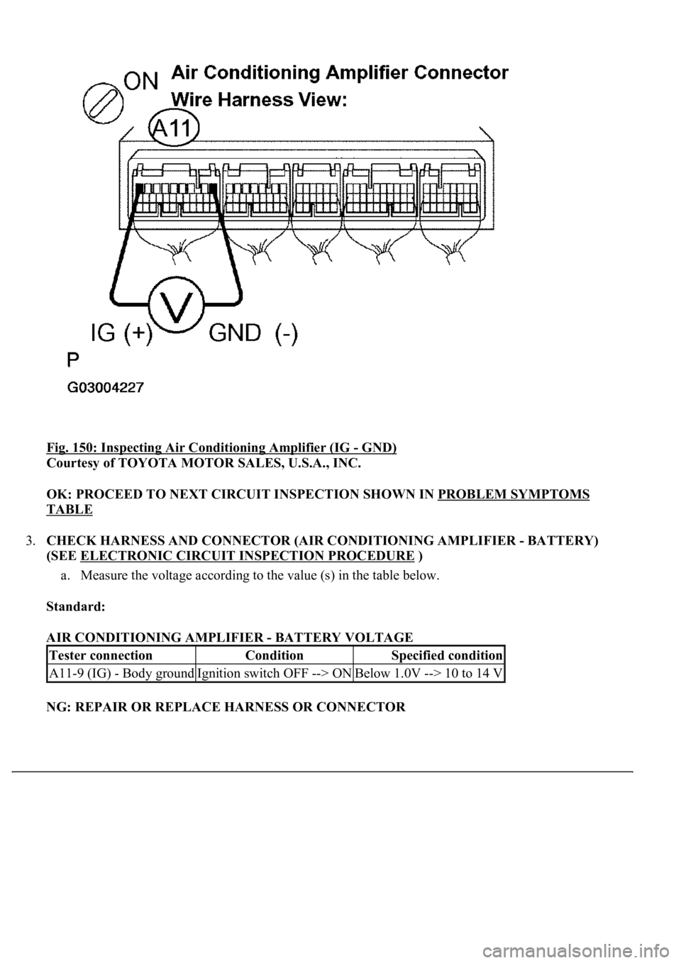
2.INSPECT AIR CONDITIONING AMPLIFIER (IG - GND)
a. Remove the A/C amplifier assy with connectors still connected.
b. Turn the ignition switch to the ON position.
c. Measure the voltage according to the value (s) in the table below.
Standard:
AIR CONDITIONING AMPLIFIER (IG - GND) VOLTAGE
NG: Go to STEP 3
Tester itemConditionSpecified condition
P-IG fuseAlwaysBelow 1 ohms
Tester connectionConditionSpecified condition
A11-9 (IG) - 14-1 (GND)Ignition switch ON10 to 14V
Page 405 of 4500
<0029004c004a00110003001400180013001d0003002c005100560053004800460057004c0051004a00030024004c005500030026005200510047004c0057004c00520051004c0051004a0003002400500053004f004c0049004c004800550003000b002c00
2a0003[- GND)
Courtesy of TOYOTA MOTOR SALES, U.S.A., INC.
OK: PROCEED TO NEXT CIRCUIT INSPECTION SHOWN IN PROBLEM SYMPTOMS
TABLE
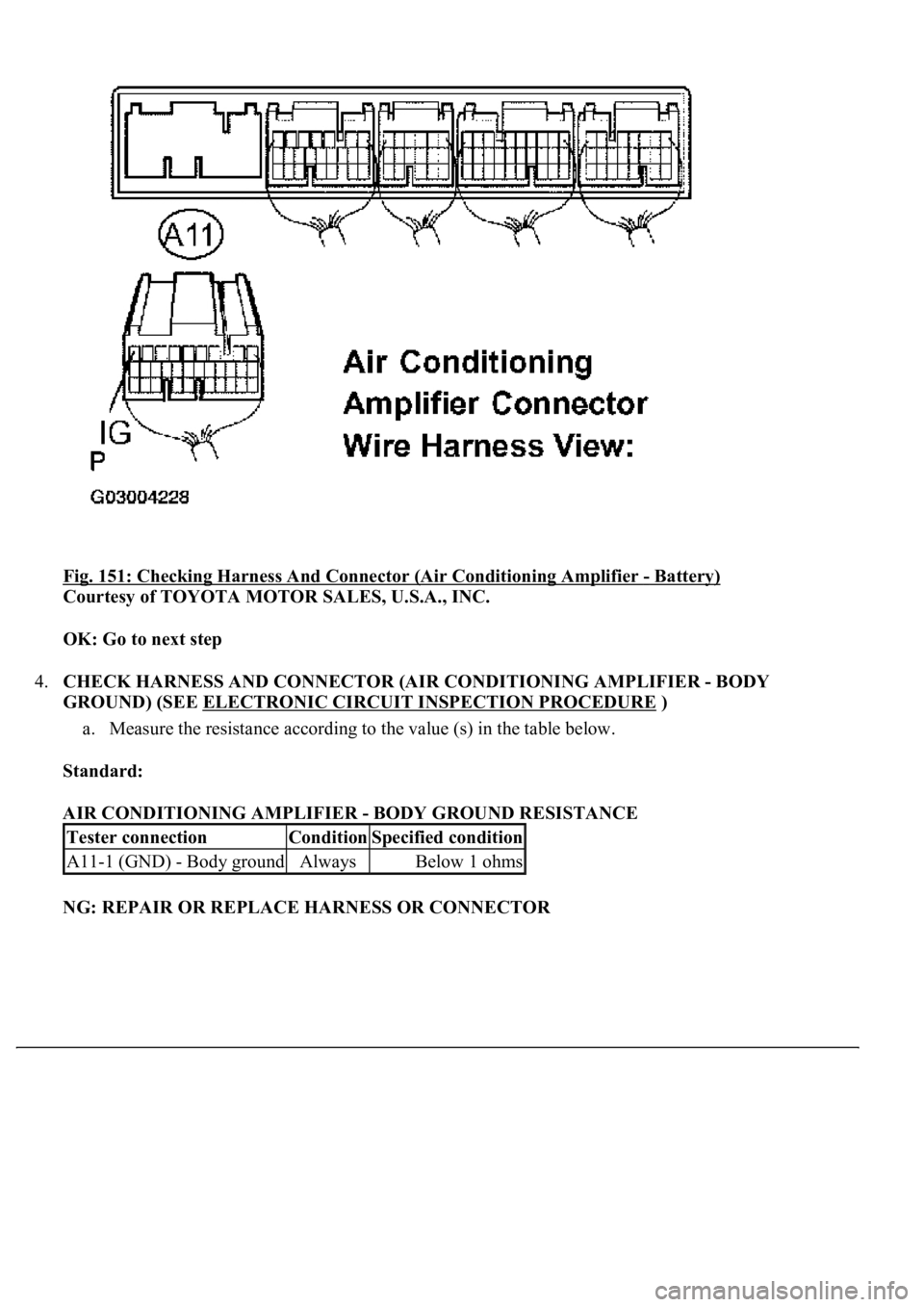
3.CHECK HARNESS AND CONNECTOR (AIR CONDITIONING AMPLIFIER - BATTERY)
(SEE ELECTRONIC CIRCUIT INSPECTION PROCEDURE
)
a. Measure the voltage according to the value (s) in the table below.
Standard:
AIR CONDITIONING AMPLIFIER - BATTERY VOLTAGE
NG: REPAIR OR REPLACE HARNESS OR CONNECTOR
Tester connectionConditionSpecified condition
A11-9 (IG) - Body groundIgnition switch OFF --> ONBelow 1.0V --> 10 to 14 V
Page 406 of 4500
Fig. 151: Checking Harness And Connector (Air Conditioning Amplifier - Battery)
Courtesy of TOYOTA MOTOR SALES, U.S.A., INC.
OK: Go to next step
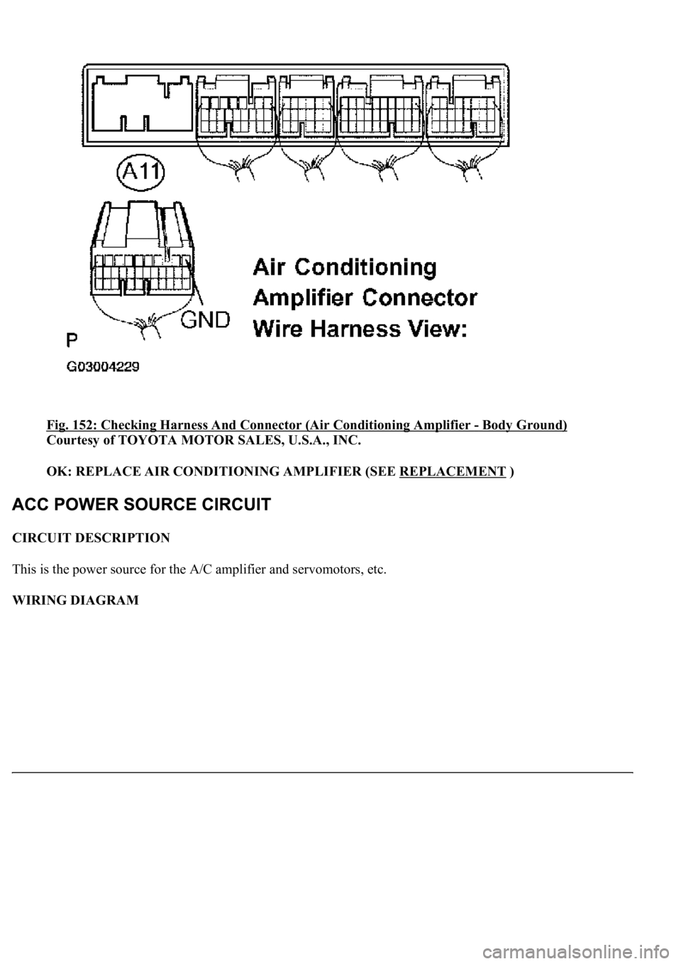
4.CHECK HARNESS AND CONNECTOR (AIR CONDITIONING AMPLIFIER - BODY
GROUND) (SEE ELECTRONIC CIRCUIT INSPECTION PROCEDURE
)
a. Measure the resistance according to the value (s) in the table below.
Standard:
AIR CONDITIONING AMPLIFIER - BODY GROUND RESISTANCE
NG: REPAIR OR REPLACE HARNESS OR CONNECTOR
Tester connectionConditionSpecified condition
A11-1 (GND) - Body groundAlwaysBelow 1 ohms
Page 407 of 4500
Fig. 152: Checking Harness And Connector (Air Conditioning Amplifier - Body Ground)
Courtesy of TOYOTA MOTOR SALES, U.S.A., INC.
OK: REPLACE AIR CONDITIONING AMPLIFIER (SEE REPLACEMENT
)
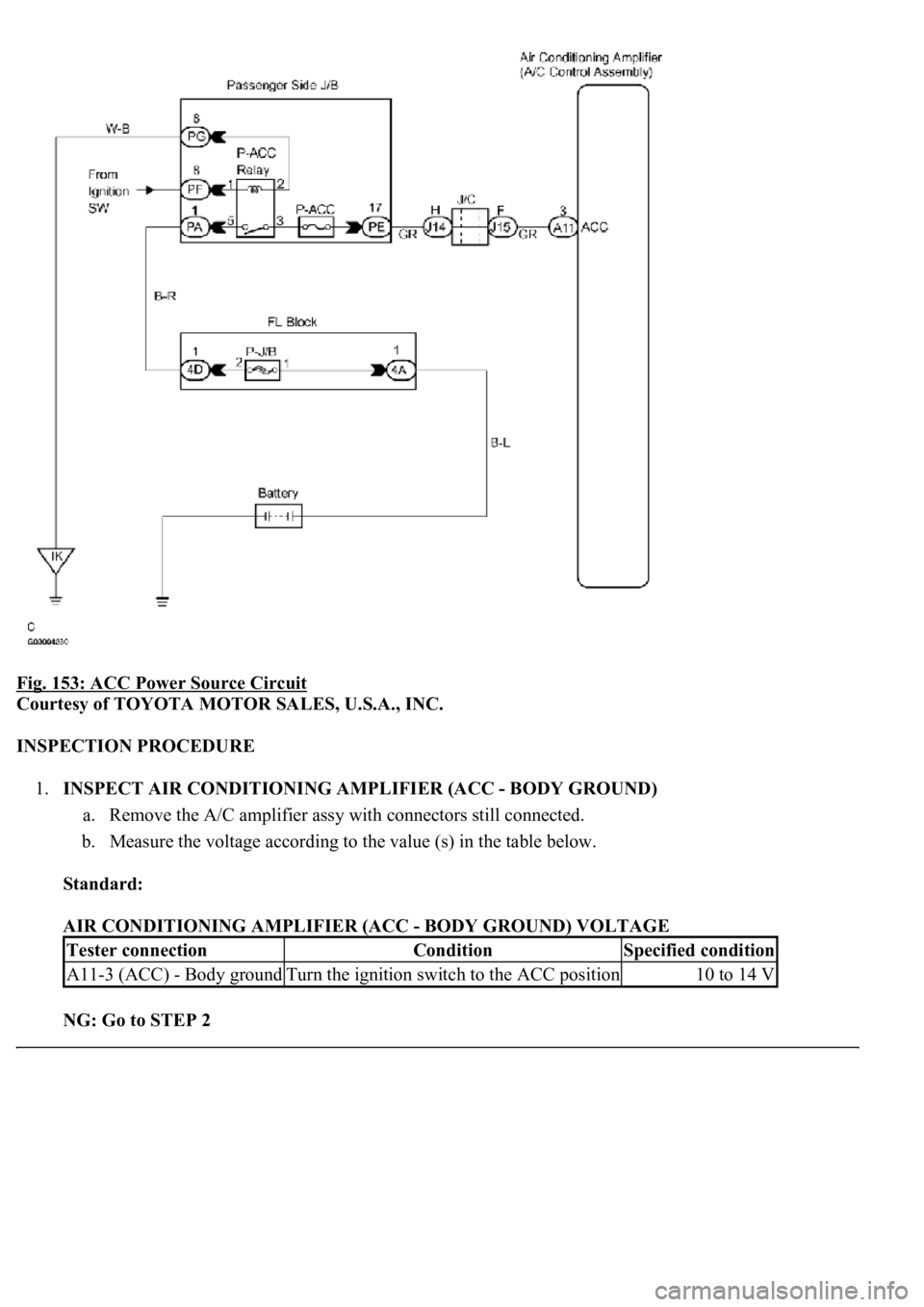
CIRCUIT DESCRIPTION
This is the power source for the A/C amplifier and servomotors, etc.
WIRING DIAGRAM
Page 408 of 4500
Fig. 153: ACC Power Source Circuit
Courtesy of TOYOTA MOTOR SALES, U.S.A., INC.
INSPECTION PROCEDURE
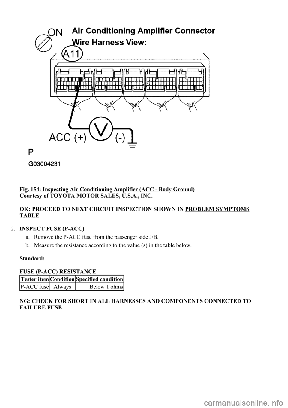
1.INSPECT AIR CONDITIONING AMPLIFIER (ACC - BODY GROUND)
a. Remove the A/C amplifier assy with connectors still connected.
b. Measure the voltage according to the value (s) in the table below.
Standard:
AIR CONDITIONING AMPLIFIER (ACC - BODY GROUND) VOLTAGE
NG: Go to STEP 2
Tester connectionConditionSpecified condition
A11-3 (ACC) - Body groundTurn the ignition switch to the ACC position10 to 14 V
Page 409 of 4500
Fig. 154: Inspecting Air Conditioning Amplifier (ACC - Body Ground)
Courtesy of TOYOTA MOTOR SALES, U.S.A., INC.
OK: PROCEED TO NEXT CIRCUIT INSPECTION SHOWN IN PROBLEM SYMPTOMS
TABLE
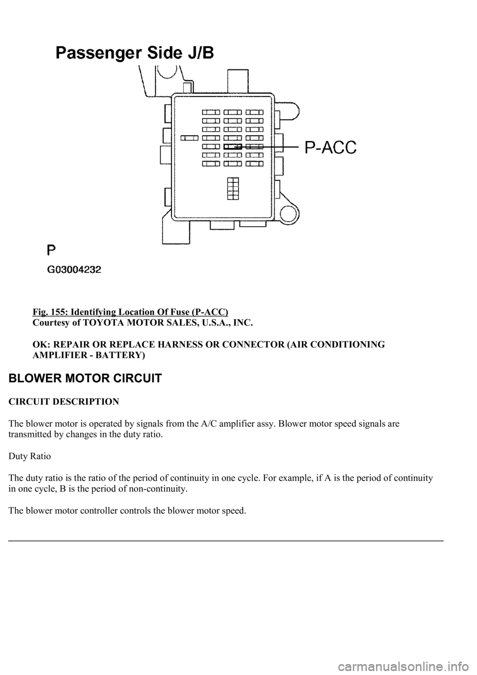
2.INSPECT FUSE (P-ACC)
a. Remove the P-ACC fuse from the passenger side J/B.
b. Measure the resistance according to the value (s) in the table below.
Standard:
FUSE (P-ACC) RESISTANCE
NG: CHECK FOR SHORT IN ALL HARNESSES AND COMPONENTS CONNECTED TO
FAILURE FUSE
Tester itemConditionSpecified condition
P-ACC fuseAlwaysBelow 1 ohms
Page 410 of 4500
Fig. 155: Identifying Location Of Fuse (P-ACC)
Courtesy of TOYOTA MOTOR SALES, U.S.A., INC.
OK: REPAIR OR REPLACE HARNESS OR CONNECTOR (AIR CONDITIONING
AMPLIFIER - BATTERY)
CIRCUIT DESCRIPTION
The blower motor is operated by signals from the A/C amplifier assy. Blower motor speed signals are
transmitted by changes in the duty ratio.
Duty Ratio
The duty ratio is the ratio of the period of continuity in one cycle. For example, if A is the period of continuity
in one cycle, B is the period of non-continuity.
The blower motor controller controls the blower motor speed.
Trending: Expansion Valve, airbag off, Absorber suspension, charging, removing v belt tensioner idler pulley, sensor, keys
