LEXUS SC400 1991 Service Repair Manual
Manufacturer: LEXUS, Model Year: 1991,
Model line: SC400,
Model: LEXUS SC400 1991
Pages: 4087, PDF Size: 75.75 MB
LEXUS SC400 1991 Service Repair Manual
SC400 1991
LEXUS
LEXUS
https://www.carmanualsonline.info/img/36/57051/w960_57051-0.png
LEXUS SC400 1991 Service Repair Manual
Trending: battery replacement, ABS, airbag, oxygen sensor, ad blue, remove seats, evap
Page 411 of 4087
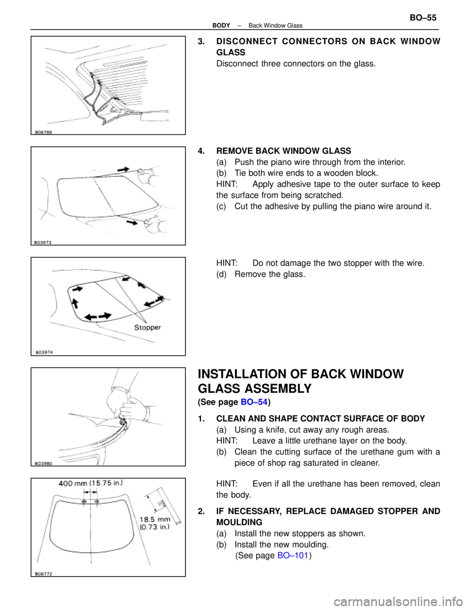
3. DISCONNECT CONNECTORS ON BACK WINDOWGLASS
Disconnect three connectors on the glass.
4. REMOVE BACK WINDOW GLASS (a) Push the piano wire through from the interior.
(b) Tie both wire ends to a wooden block.
HINT: Apply adhesive tape to the outer surface to keep
the surface from being scratched.
(c) Cut the adhesive by pulling the piano wire around it.
HINT: Do not damage the two stopper with the wire.
(d) Remove the glass.
INSTALLATION OF BACK WINDOW
GLASS ASSEMBLY
(See page BO±54)
1. CLEAN AND SHAPE CONTACT SURFACE OF BODY (a) Using a knife, cut away any rough areas.
HINT: Leave a little urethane layer on the body.
(b) Clean the cutting surface of the urethane gum with apiece of shop rag saturated in cleaner.
HINT: Even if all the urethane has been removed, clean
the body.
2. IF NECESSARY, REPLACE DAMAGED STOPPER AND MOULDING
(a) Install the new stoppers as shown.
(b) Install the new moulding. (See page BO±101)
±
BODY Back Window GlassBO±55
WhereEverybodyKnowsYourName
Page 412 of 4087
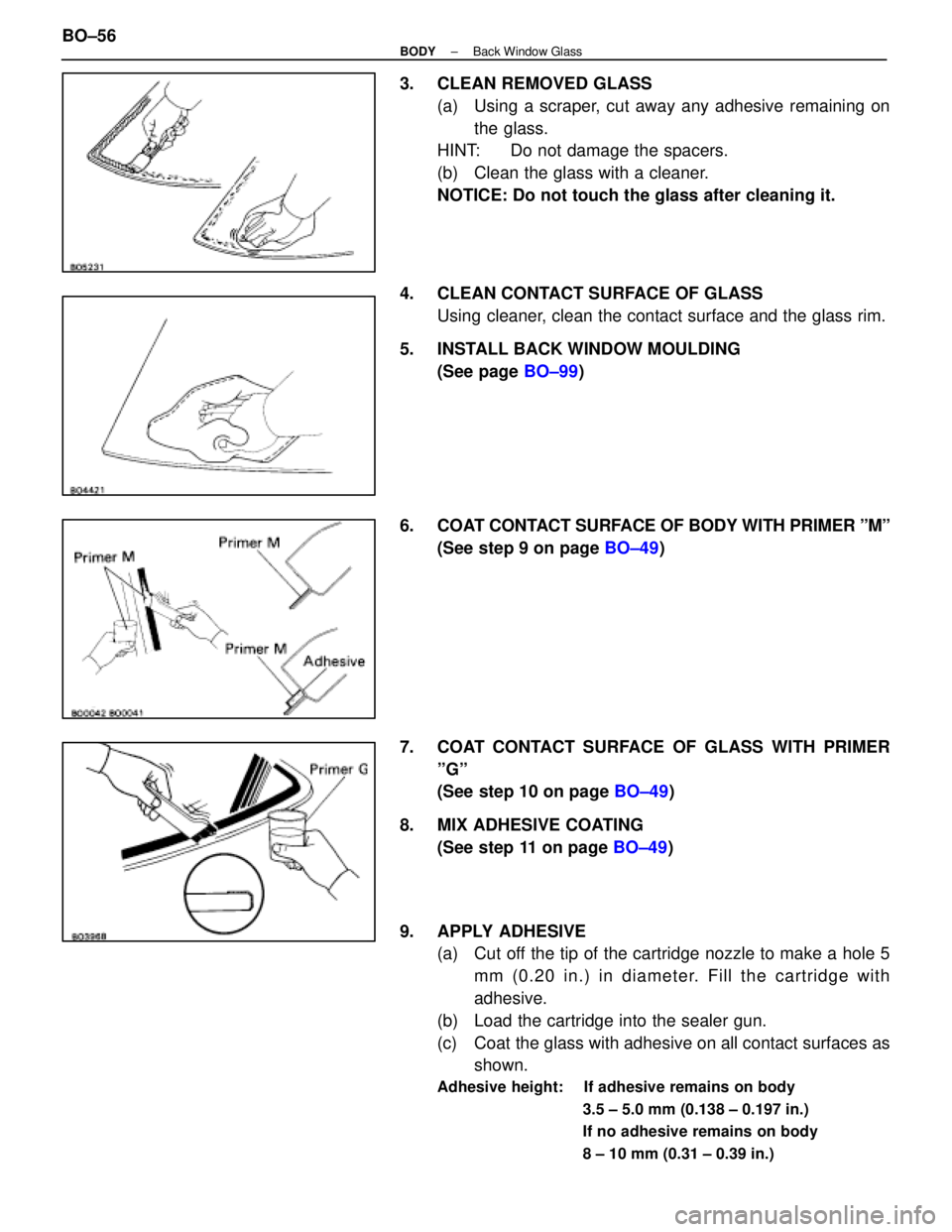
3. CLEAN REMOVED GLASS(a) Using a scraper, cut away any adhesive remaining onthe glass.
HINT: Do not damage the spacers.
(b) Clean the glass with a cleaner.
NOTICE: Do not touch the glass after cleaning it.
4. CLEAN CONTACT SURFACE OF GLASS Using cleaner, clean the contact surface and the glass rim.
5. INSTALL BACK WINDOW MOULDING (See page BO±99)
6. COAT CONTACT SURFACE OF BODY WITH PRIMER ºMº (See step 9 on page BO±49)
7. COAT CONTACT SURFACE OF GLASS WITH PRIMER ºGº
(See step 10 on page BO±49)
8. MIX ADHESIVE COATING (See step 11 on page BO±49)
9. APPLY ADHESIVE (a) Cut off the tip of the cartridge nozzle to make a hole 5
mm (0.20 in.) in diameter. Fill the cartridge with
adhesive.
(b) Load the cartridge into the sealer gun.
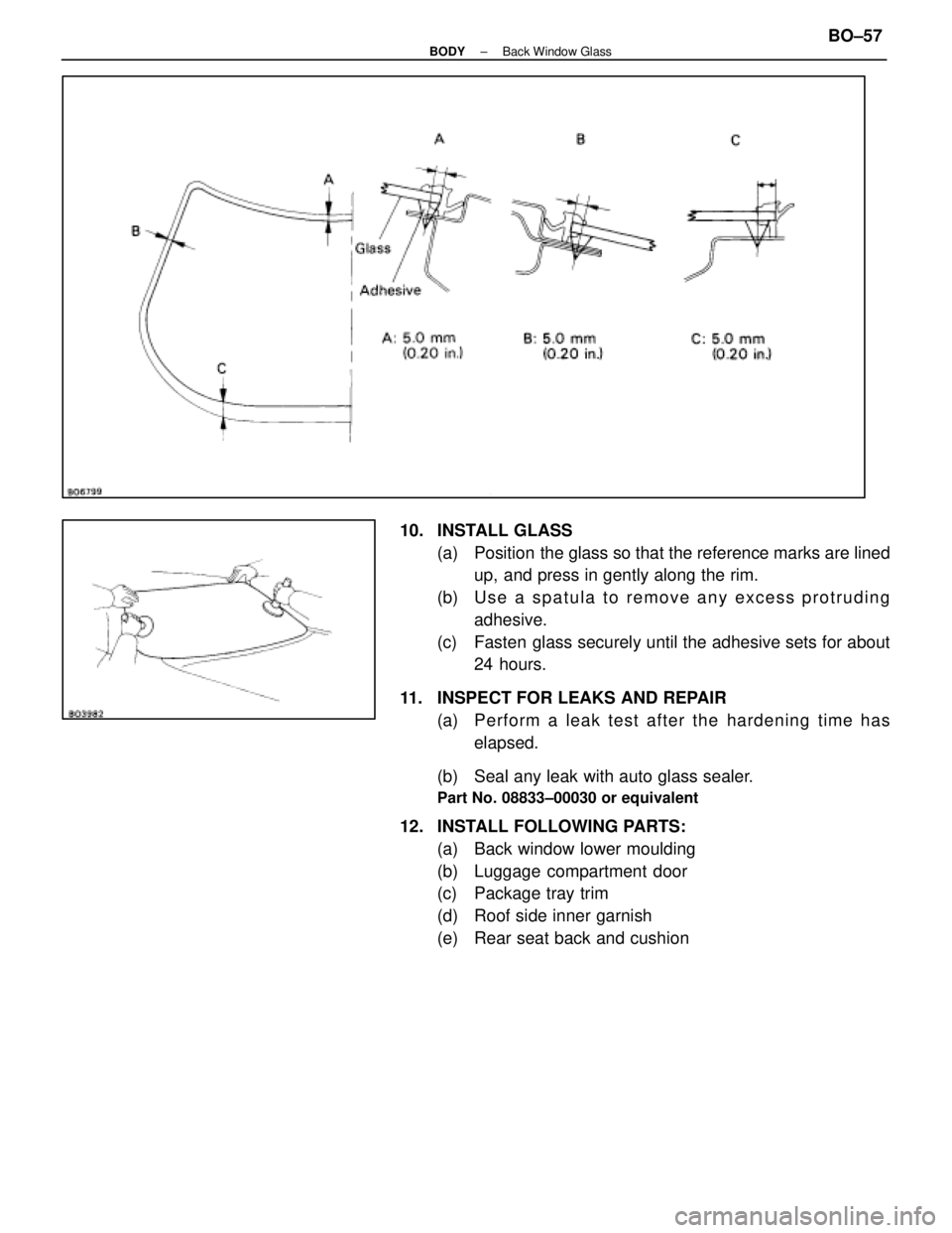
(c) Coat the glass with adhesive on all contact surfaces as shown.
Adhesive height: If adhesive remains on body
3.5 ± 5.0 mm (0.138 ± 0.197 in.)
If no adhesive remains on body
8 ± 10 mm (0.31 ± 0.39 in.)
BO±56±
BODY Back Window Glass
WhereEverybodyKnowsYourName
Page 413 of 4087
10. INSTALL GLASS(a) Position the glass so that the reference marks are linedup, and press in gently along the rim.
(b) U s e a s p a t u l a t o r e m o v e a n y e x c e s s p r o t r u d i n g adhesive.
(c) Fasten glass securely until the adhesive sets for about 24 hours.
11. INSPECT FOR LEAKS AND REPAIR (a) P e rfo rm a le a k te st afte r th e ha r dening time has
elapsed.
(b) Seal any leak with auto glass sealer.
Part No. 08833±00030 or equivalent
12. INSTALL FOLLOWING PARTS: (a) Back window lower moulding
(b) Luggage compartment door
(c) Package tray trim
(d) Roof side inner garnish
(e) Rear seat back and cushion
±
BODY Back Window GlassBO±57
WhereEverybodyKnowsYourName
Page 414 of 4087
SEAT
Front Seat
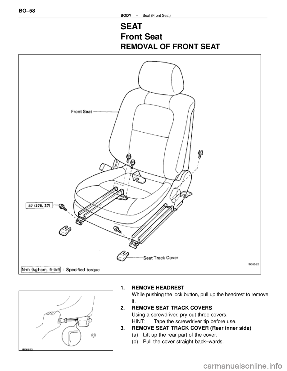
REMOVAL OF FRONT SEAT
1. REMOVE HEADRESTWhile pushing the lock button, pull up the headrest to remove
it.
2. REMOVE SEAT TRACK COVERS Using a screwdriver, pry out three covers.
HINT: Tape the screwdriver tip before use.
3. REMOVE SEAT TRACK COVER (Rear inner side)
(a) Lift up the rear part of the cover.
(b) Pull the cover straight back±wards.
BO±58
±
BODY Seat (Front Seat)
WhereEverybodyKnowsYourName
Page 415 of 4087
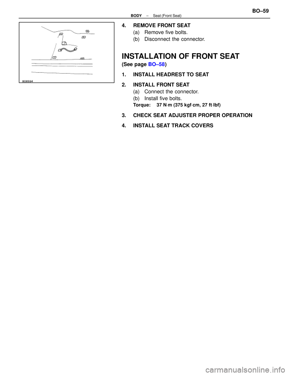
4. REMOVE FRONT SEAT(a) Remove five bolts.
(b) Disconnect the connector.
INSTALLATION OF FRONT SEAT
(See page BO±58)
1. INSTALL HEADREST TO SEAT
2. INSTALL FRONT SEAT (a) Connect the connector.
(b) Install five bolts.
Torque: 37 N Vm (375 kgf Vcm, 27 ft Vlbf)
3. CHECK SEAT ADJUSTER PROPER OPERATION
4. INSTALL SEAT TRACK COVERS
±
BODY Seat (Front Seat)BO±59
WhereEverybodyKnowsYourName
Page 416 of 4087
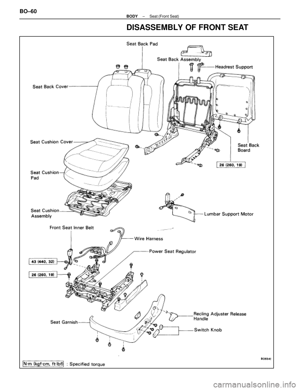
DISASSEMBLY OF FRONT SEAT
BO±60±
BODY Seat (Front Seat)
WhereEverybodyKnowsYourName
Page 417 of 4087
BO6562
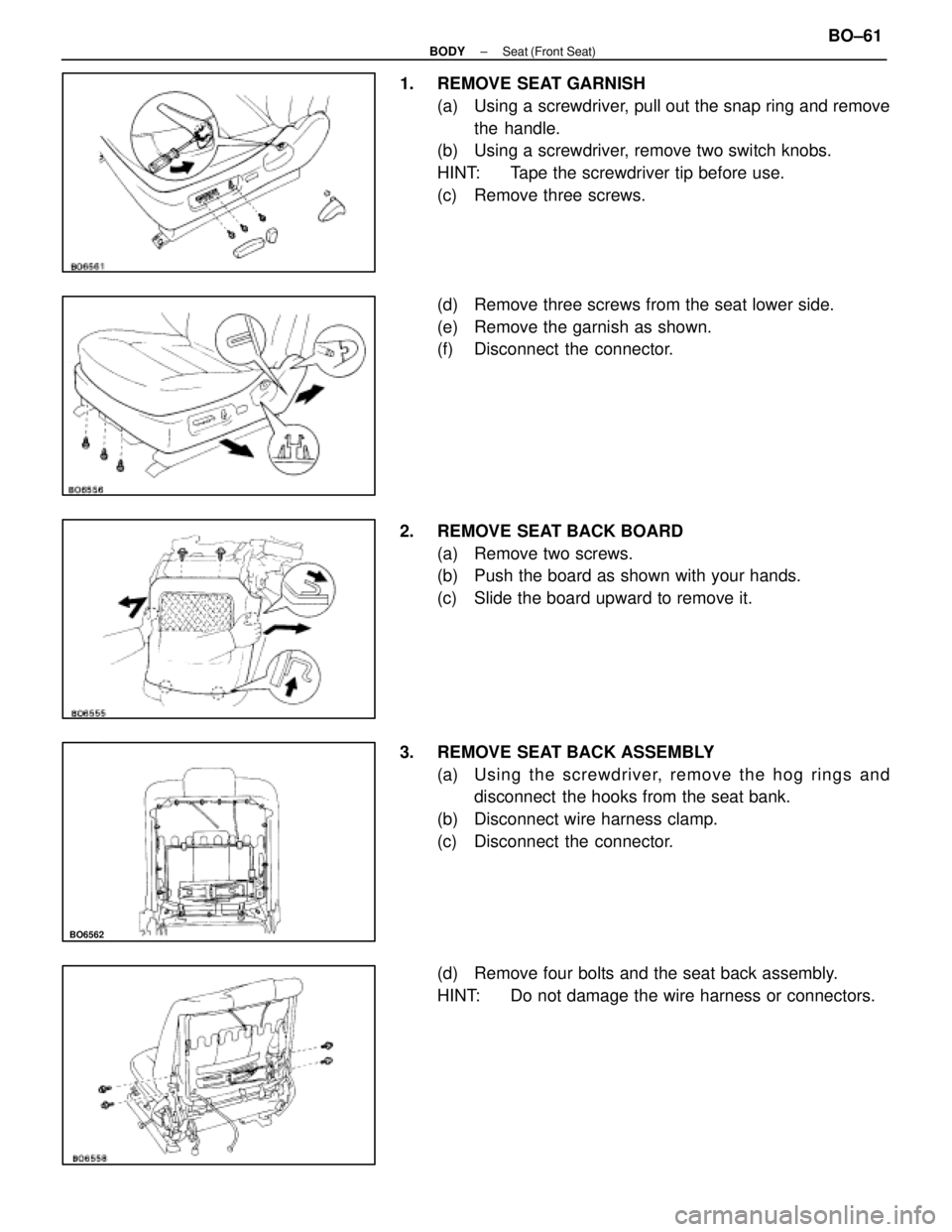
1. REMOVE SEAT GARNISH(a) Using a screwdriver, pull out the snap ring and removethe handle.
(b) Using a screwdriver, remove two switch knobs.
HINT: Tape the screwdriver tip before use.
(c) Remove three screws.
(d) Remove three screws from the seat lower side.
(e) Remove the garnish as shown.
(f) Disconnect the connector.
2. REMOVE SEAT BACK BOARD (a) Remove two screws.
(b) Push the board as shown with your hands.
(c) Slide the board upward to remove it.
3. REMOVE SEAT BACK ASSEMBLY (a) Usin g th e scre wd rive r, re mo ve th e ho g rin g s an ddisconnect the hooks from the seat bank.
(b) Disconnect wire harness clamp.
(c) Disconnect the connector.
(d) Remove four bolts and the seat back assembly.
HINT: Do not damage the wire harness or connectors.
±
BODY Seat (Front Seat)BO±61
WhereEverybodyKnowsYourName
Page 418 of 4087
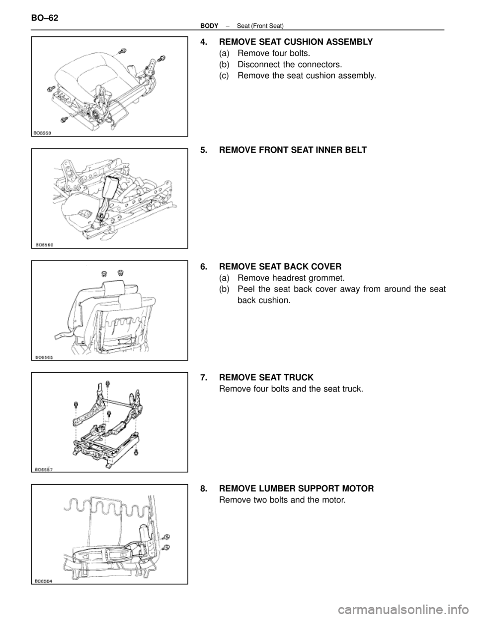
4. REMOVE SEAT CUSHION ASSEMBLY(a) Remove four bolts.
(b) Disconnect the connectors.
(c) Remove the seat cushion assembly.
5. REMOVE FRONT SEAT INNER BELT
6. REMOVE SEAT BACK COVER (a) Remove headrest grommet.
(b) Peel the seat back cover away from around the seatback cushion.
7. REMOVE SEAT TRUCK Remove four bolts and the seat truck.
8. REMOVE LUMBER SUPPORT MOTOR Remove two bolts and the motor.
BO±62
±
BODY Seat (Front Seat)
WhereEverybodyKnowsYourName
Page 419 of 4087
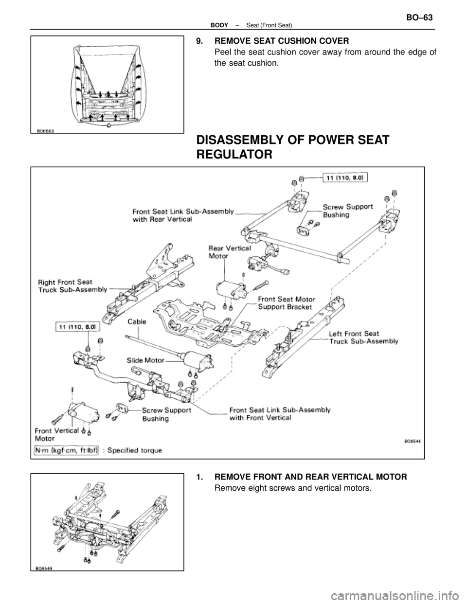
9. REMOVE SEAT CUSHION COVERPeel the seat cushion cover away from around the edge of
the seat cushion.
DISASSEMBLY OF POWER SEAT
REGULATOR
1. REMOVE FRONT AND REAR VERTICAL MOTORRemove eight screws and vertical motors.
±
BODY Seat (Front Seat)BO±63
WhereEverybodyKnowsYourName
Page 420 of 4087
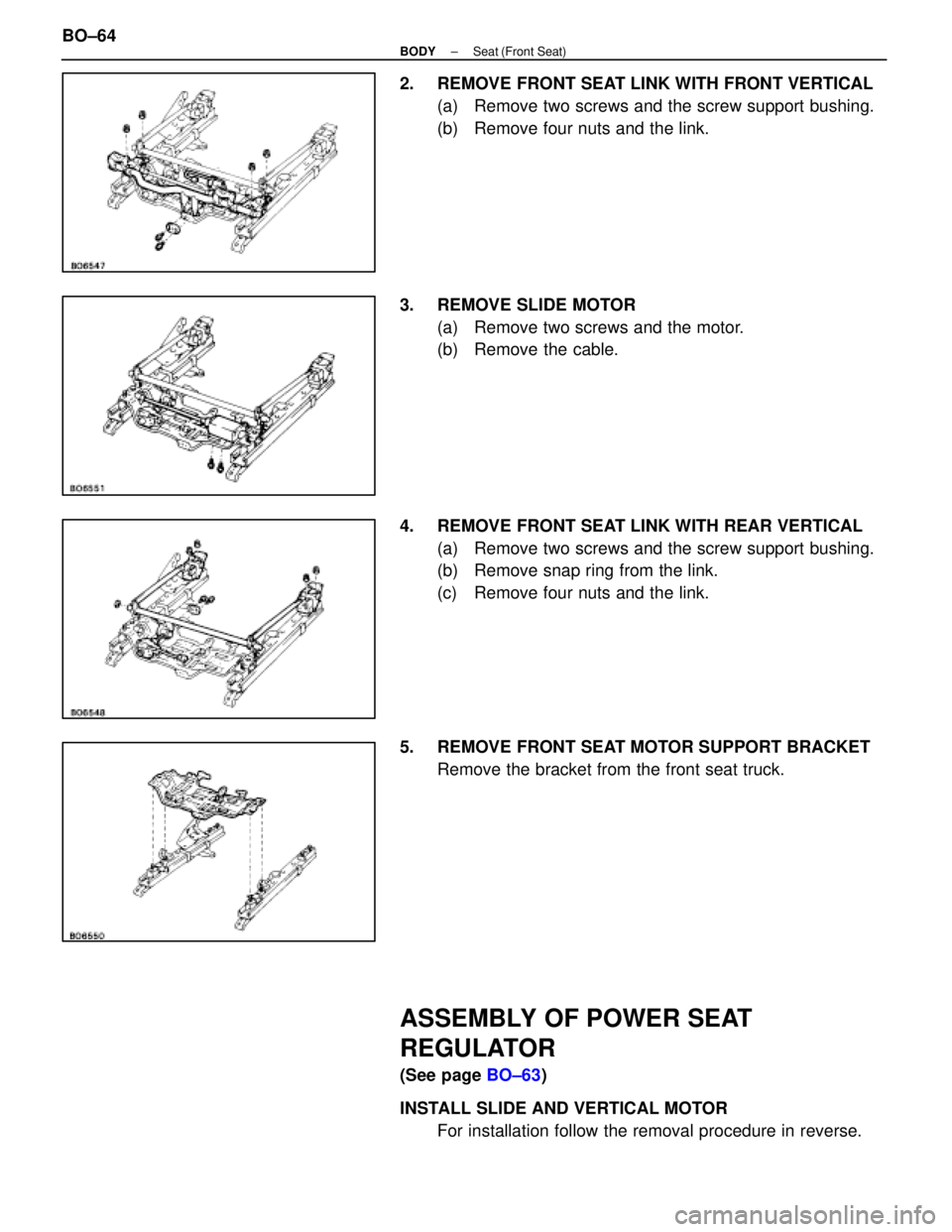
2. REMOVE FRONT SEAT LINK WITH FRONT VERTICAL(a) Remove two screws and the screw support bushing.
(b) Remove four nuts and the link.
3. REMOVE SLIDE MOTOR (a) Remove two screws and the motor.
(b) Remove the cable.
4. REMOVE FRONT SEAT LINK WITH REAR VERTICAL (a) Remove two screws and the screw support bushing.
(b) Remove snap ring from the link.
(c) Remove four nuts and the link.
5. REMOVE FRONT SEAT MOTOR SUPPORT BRACKET Remove the bracket from the front seat truck.
ASSEMBLY OF POWER SEAT
REGULATOR
(See page BO±63)
INSTALL SLIDE AND VERTICAL MOTOR For installation follow the removal procedure in reverse.
BO±64
±
BODY Seat (Front Seat)
WhereEverybodyKnowsYourName
Trending: service interval, tire size, fuel type, ignition buzzer, high beam, compression ratio, fuel tank removal
