MAZDA 323 1992 Workshop Manual Suplement
Manufacturer: MAZDA, Model Year: 1992,
Model line: 323,
Model: MAZDA 323 1992
Pages: 279, PDF Size: 24.15 MB
MAZDA 323 1992 Workshop Manual Suplement
323 1992
MAZDA
MAZDA
https://www.carmanualsonline.info/img/28/57055/w960_57055-0.png
MAZDA 323 1992 Workshop Manual Suplement
Trending: power steering, recommended oil, technical specifications, oil type, change time, height, wiring diagram
Page 141 of 279
S SUPPLEMENTAL SERVICE INFORMATION
SUPPLEMENTAL SERVICE lNFORMATlON
The following points in this section are changed in comparison with 323 Workshop Manual (1229-~()439~).
*
BONNET BULGE
l Removal / installation
FRONT BUMPER
l Removal / Installation
REAR SKIRT
l Removal / Installation
WHEEL ARCf-f MOLDfNG
l Removal / Installation
13EOSX-310
S-6
BONNE
COMPOh
Rembvaf
1. Removi
2. lnstatl if
Page 142 of 279
BONNET BULGE S
BONNET BULGE
COMPONENTS
Rem&at ! Installation
1. Removal in the order shown in the
figure.
2. Install in the reverse order of removal.
I . Bonnet butge’
Page 143 of 279
S
FRONT BUMPER FRONT BUMPER
COMPONENTS
Rem’ovat ! Installation
1. Removal in the order shown
2. Install in the reverse order of
1 in the figure.
removal.
-9-9.8 Nm 170-100 kgfem,
U-87 h.lbfJ
f4-m Ikgf-m, ft-lbf J
13EOSX-312
4. Front bumper
Disassembly / Assembly
. . . . . . . . . ..m... page S-9 1. Radiator grille
2. Front conbination light
3. Headlight
5-8
Disassembh
I . Disassemi
2. Assemble
t
1. Fog lights
-
a
-I. 2. Bumper rear
3. Bumper me
Page 144 of 279
FRONT BUMPER S
Disassembly / Assembly
I. Disassemble in the order shown in the figure.
2. Assemble in the reverse order of disassembly.
i
1, Fog lights
2. Bumper reinforcement
3. Bumper mesh 4. Hook cover
5. Bumper fascia
Page 145 of 279
S REAR SKIRT
REAR SKIRT -
COMPONENTS
Rembal / Installation
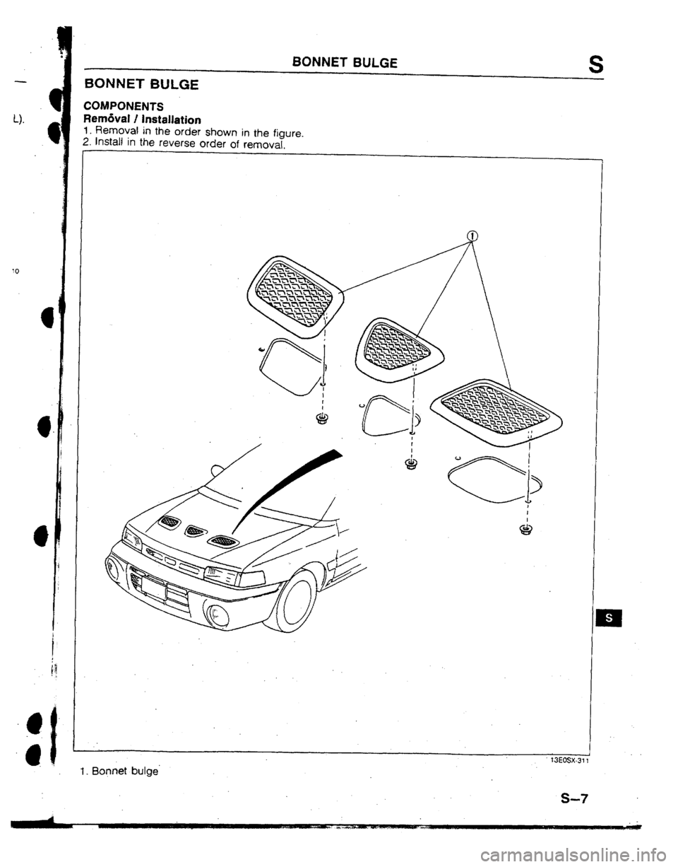
1. Remove in the order shown in the figure.
2. Install in the reverse order of removal.
Note
l Remove the rear bumper to remove and install the rear skirt.
1. Rear skit-! 2. Rear bumper
S-10 WHEEL,
COMPONE
Removal I
1. Remove i
2. Install in t
I, Front why
Removi
I nstallat
Page 146 of 279
WHEEL ARCH MOLDING S
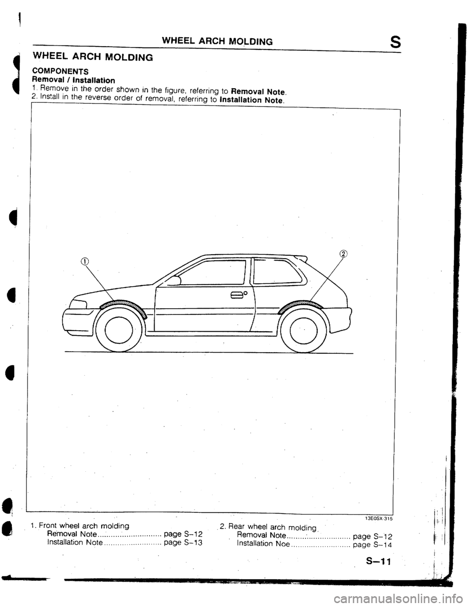
WHEEL ARCH MOLDING
COMPONENTS
Removal I installation
1 Remove in the order shown in the figure referring to Removal Note
2.
Install in the reverse order nf rernmtal
rA*rrinh h Inr+dld:nm
&l-r- ’
lXOSX-31
1, Front wheel arch molding
- - 2. Rear wheel arch molding
Hemoval Note .............................. page S-l 2
Removal Note ............. .
Installation Note.. ................
page S-13 installation Noe page S-I 2
I I / ;
........................
........................... page S-14
S-t 1
Page 147 of 279
S
Removal Note
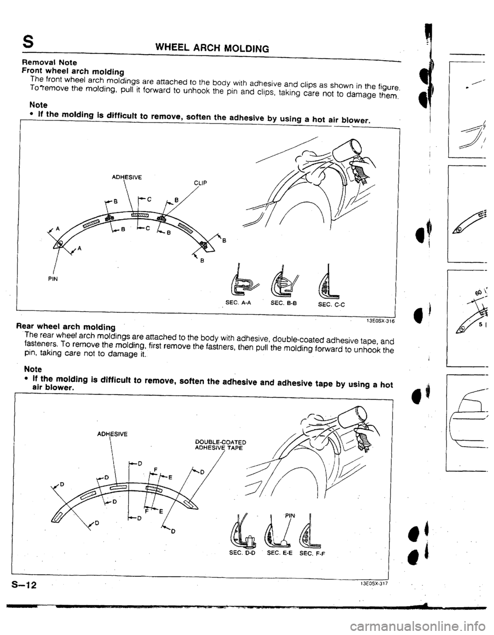
Front wheel arch molding
WHEEL ARCH MOLDING
The front wheel arch moldings are attached to the body with adhesive and clips as shown in the figure
To?emove the molding, puti it forward to unhook the pin and clips, taking care not
to damage them,’
Note
. If the molding is difficult to remove, soften the adhesive by using a hot air blower.
->7
ADHESIVE
SEC. A-A
SEC. B-B
SEC. C-C
Rear wheel arch molding 13EosX-316
‘The rear wheel arch moldings are attached to the body with adhesive, double-coated adhesive tape and
fasteners. To remove the motding, first remove the fastners, then pull the molding forward to unhook the
pin, taking care not to damage it.
Note
l If the molding is difficuft to remove, soften the adhesive and adhesive tape by using a hot
air blower.
ADHESIVE
DOUBLE-COATED
ADHESIVE TAPE
SEC. D-D
SEC. E-E SEC. F-F
Page 148 of 279
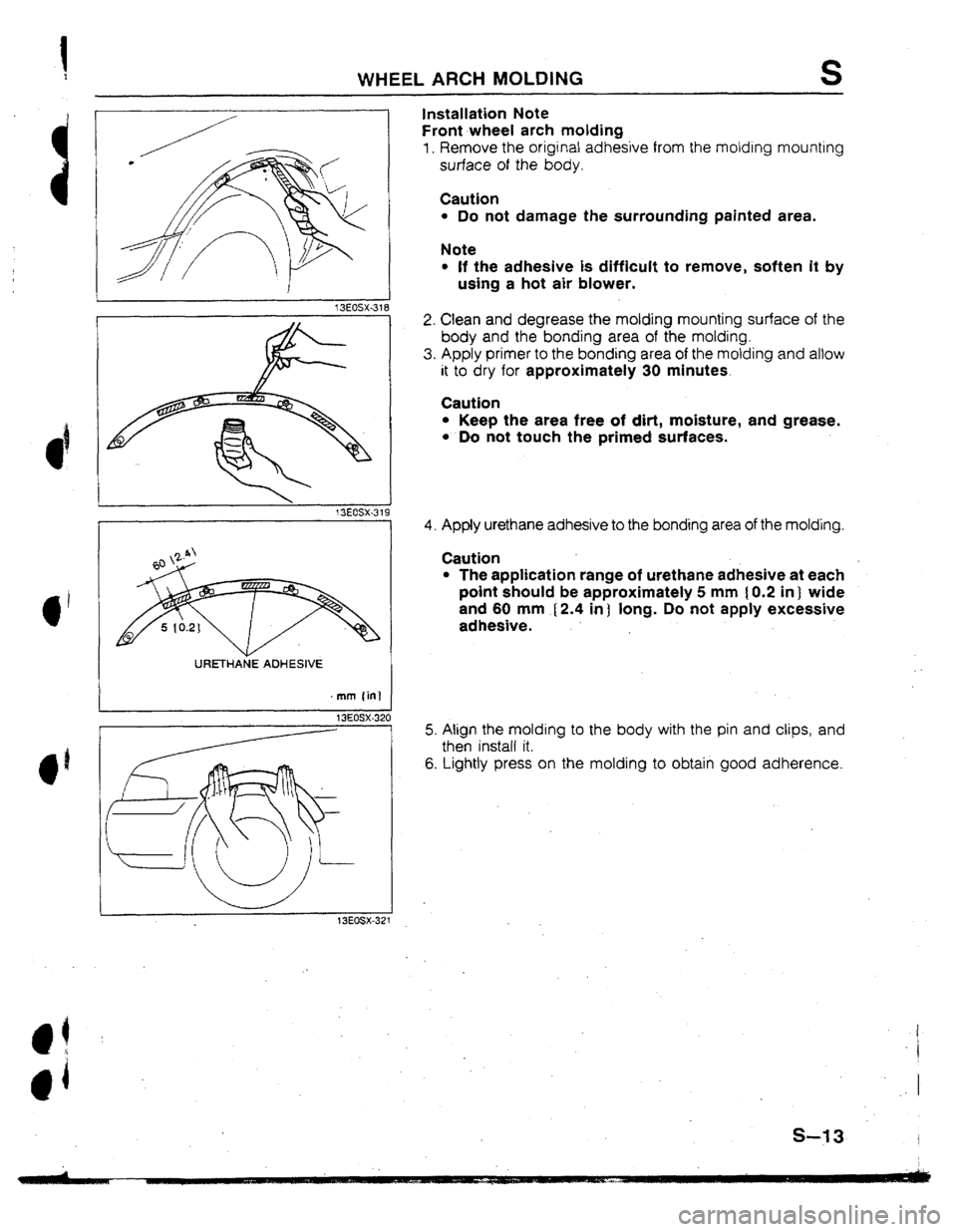
WHEEL ARCH MOLDING
Installation
Note
S
Front wheel arch molding
1. Remove the original adhesive from the molding mounting
surface of the body.
Caution
l Do not damage the surrounding painted area.
Note
l If the adhesive is difficult to remove, soften it by
using a hot air blower.
I URETHAtiE ADHESIVE
I
13EOSX-320
13EOSX-321
2. Clean and degrease the molding mounting surface of the
body and the bonding area of the molding.
3. Apply primer to the bonding area of the molding and allow
it to dry for approximately 30 minutes.
Caution
l Keep the area free of dirt, moisture, and grease.
l Do not touch the primed surfaces.
4. Apply urethane adhesive to the bonding area of the molding.
Caution
l The application range of urethane adhesive at each
point should be approximately 5 mm [ 0.2 in 1 wide
and 60 mm [ 2.4 in 1 long. Do not apply excessive
adhesive.
5. Align the molding to the body with the pin and clips, and
then install it.
6. Lightly press on the molding to obtain good adherence.
1
i
1
S-f 3 I
Page 149 of 279
![MAZDA 323 1992 Workshop Manual Suplement S WHEEL ARCH MOLDING
13EOSX-323
r
ADHESIVE TAPE
mm fin]
f 3EOSX-324
13EOSX.325
s-14.
Rear wheel arch molding
1. Remove the original adhesive from the molding mounting
surface of the body.
C MAZDA 323 1992 Workshop Manual Suplement S WHEEL ARCH MOLDING
13EOSX-323
r
ADHESIVE TAPE
mm fin]
f 3EOSX-324
13EOSX.325
s-14.
Rear wheel arch molding
1. Remove the original adhesive from the molding mounting
surface of the body.
C](/img/28/57055/w960_57055-148.png)
S WHEEL ARCH MOLDING
13EOSX-323
r
ADHESIVE TAPE
mm fin]
f 3EOSX-324
13EOSX.325
s-14.
Rear wheel arch molding
1. Remove the original adhesive from the molding mounting
surface of the body.
Caution
l Do not damage the surrounding painted area.
Note
l tf the adhesive is difficult to remove, soften it by
using a hot air blower.
2. Clean and degrease the molding mounting surface of the
body and the bonding area of the molding.
3. Apply primer to the bonding area of the molding and allow
it to dry for approximately 30 minutes.
Caution
l Keep the area free of dirt, moisture, and grease.
l Do not touch the primed surfaces.
4. Apply strips of double-coated adhesive tape to the bond-
ing area of the molding.
Note
l Use 40 mm I-1.6 in) lengths of tape.
5. Apply urethane adhesive to the bonding area of the molding.
Caution
l The application range of urethane adhesive should
be approximately 5 mm f 0.2 iii ) wide and 60 mm
(2.4 in) long. Do not apply excessive adhesive.
6. Peel the protection paper from the double-coated adhesive
tape.
7. Align the molding to the body with the pin, and then install it,
8. Lightly press on the molding to obtain good adherence.
9. tnstall the fasteners.
Page 150 of 279
T
BODY ELECTRICAL SYSTEM
INDEX .*,........,..............*....*...*.........*....*.*.
T- 2
jFEATURESl
OUTLINE . . . . . . ..*.....*..*...~.=.........*.*........*~...~
T- 3
FEATURES .e . . . . . *..* . . . . . . * . . . . . . * . . . . . . . *..I . . . . . . . . .
T- 3
LIGHTING SYSTEM .,....*.*..m...*..,...,a*..*.*..,..
T- 3
SPECIFICATDNS .I..*.*...*....*....*.............,.
T- 3
SUPPLEMENTAL SERVICE
INFORMATlON I . . . . . . . . . . . . . . . . . *.*.a=..* . . . . . . . *..*.s
T- ,4
EXTERlOR LlGHTlNG SYSTEM . . . . .
l . . ..e.am..a.. T-
4
FRONT FOG LIGHT
. . . . . . n .* . . . . . l ...* . . . . . s* .,..I..
T- 4
f3EOTX-301
H .
Trending: brake sensor, fog light, instrument panel, warning light, interior lights, service schedule, fuel tank capacity



![MAZDA 323 1992 Workshop Manual Suplement S WHEEL ARCH MOLDING
13EOSX-323
r
ADHESIVE TAPE
mm fin]
f 3EOSX-324
13EOSX.325
s-14.
Rear wheel arch molding
1. Remove the original adhesive from the molding mounting
surface of the body.
C MAZDA 323 1992 Workshop Manual Suplement S WHEEL ARCH MOLDING
13EOSX-323
r
ADHESIVE TAPE
mm fin]
f 3EOSX-324
13EOSX.325
s-14.
Rear wheel arch molding
1. Remove the original adhesive from the molding mounting
surface of the body.
C](/img/28/57055/w960_57055-148.png)
