wiring MAZDA 6 2002 Suplement User Guide
[x] Cancel search | Manufacturer: MAZDA, Model Year: 2002, Model line: 6, Model: MAZDA 6 2002Pages: 909, PDF Size: 17.16 MB
Page 204 of 909
F2–52
FUEL SYSTEM
SEDIMENTOR WATER DRAININGA6E4012348022041. Disconnect the negative battery cable.
2. Complete the “BEFORE REPAIR PROCEDURE”. (See F2–45 BEFORE REPAIR PROCEDURE.)
3. Loosen the drain plug located at the bottom of the fuel filter.
4. Pump the priming pump and drain the water.
5. After all the water has been drained, tighten the drain plug.
6. Complete the “AFTER REPAIR PROCEDURE”. (See F2–45 AFTER REPAIR PROCEDURE.)
7. Reconnect the negative battery cable.
End Of Sie
SEDIMENTOR SWITCH INSPECTIONA6E401213840201
Note
•Perform the following test only when directed.
1. Disconnect the negative battery cable.
2. Complete the “BEFORE REPAIR PROCEDURE”. (See F2–45 BEFORE REPAIR PROCEDURE.)
3. Drain fuel from the fuel filter. (See F2–52 SEDIMENTOR WATER DRAINING.)
4. Remove the sedimentor switch.
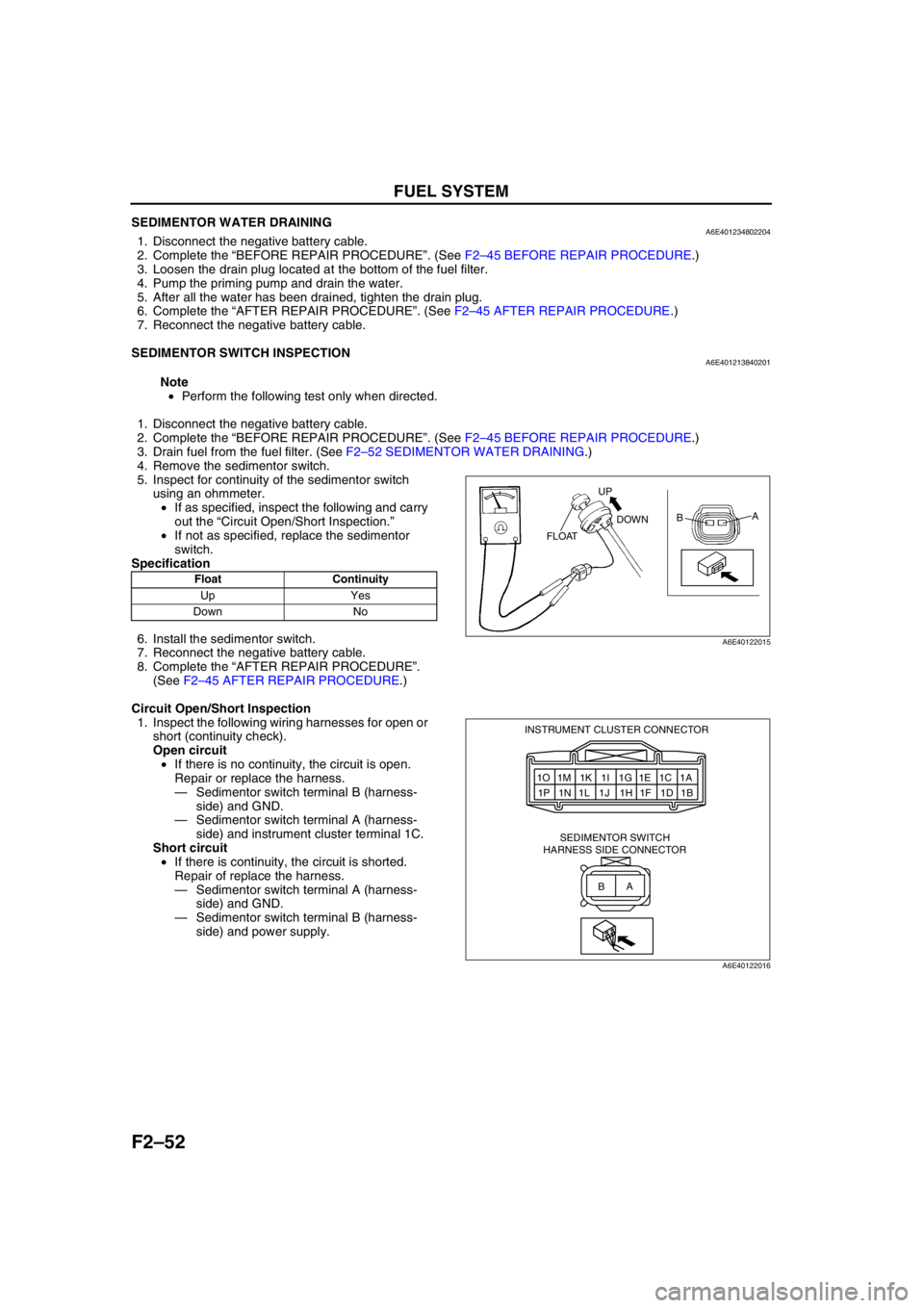
5. Inspect for continuity of the sedimentor switch
using an ohmmeter.
•If as specified, inspect the following and carry
out the “Circuit Open/Short Inspection.”
•If not as specified, replace the sedimentor
switch.
Specification
6. Install the sedimentor switch.
7. Reconnect the negative battery cable.
8. Complete the “AFTER REPAIR PROCEDURE”.
(See F2–45 AFTER REPAIR PROCEDURE.)
Circuit Open/Short Inspection
1. Inspect the following wiring harnesses for open or
short (continuity check).
Open circuit
•If there is no continuity, the circuit is open.
Repair or replace the harness.
—Sedimentor switch terminal B (harness-
side) and GND.
—Sedimentor switch terminal A (harness-
side) and instrument cluster terminal 1C.
Short circuit
•If there is continuity, the circuit is shorted.
Repair of replace the harness.
—Sedimentor switch terminal A (harness-
side) and GND.
—Sedimentor switch terminal B (harness-
side) and power supply.
End Of Sie
Float Continuity
Up Yes
Down No
UP
DOWN
FLOATA
B
A6E40122015
1O 1M 1K 1I 1G 1E 1C 1A
1P 1N 1L 1J 1H 1F 1D 1B INSTRUMENT CLUSTER CONNECTOR
SEDIMENTOR SWITCH
HARNESS SIDE CONNECTOR
A
B
A6E40122016
Page 206 of 909
F2–54
FUEL SYSTEM
SUPPLY PUMP INSPECTIONA6E401213350202
Caution
•The supply pump is sealed to maintain proper function. Special tools and testers are required
when disassembling the supply pump. Disassembling the supply pump without special tools and
testers will cause a malfunction.
•Consult an authorized DENSO parts distributor for repair if any of the following supply pump parts
are possibly malfunctioning.
1. Supply pump inner parts
2. Suction control valve
3. Fuel temperature sensor
End Of Sie
SUCTION CONTROL VALVE INSPECTIONA6E401213350203
Caution
•The supply pump is sealed to maintain proper function. Special tools and testers are required
when disassembling the supply pump. Disassembling the supply pump without special tools and
testers will cause a malfunction.
•Consult an authorized DENSO parts distributor for repair if suction control valve is possibly
malfunctioning.
Resistance Inspection
1. Disconnect the negative battery cable.
2. Disconnect the suction control valve connector.
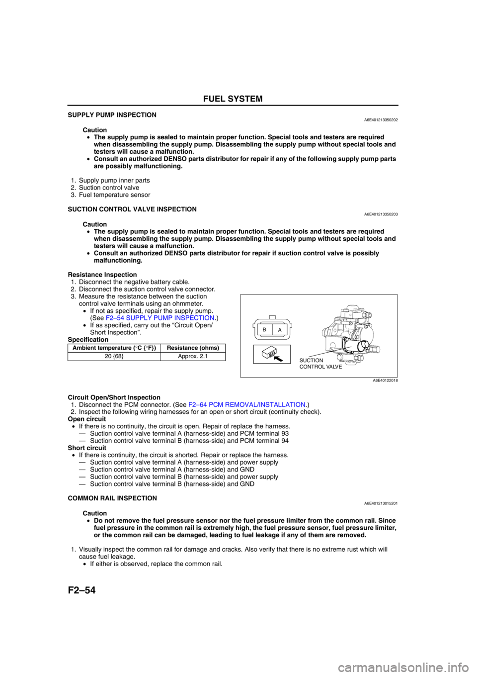
3. Measure the resistance between the suction
control valve terminals using an ohmmeter.
•If not as specified, repair the supply pump.
(See F2–54 SUPPLY PUMP INSPECTION.)
•If as specified, carry out the “Circuit Open/
Short Inspection”.
Specification
Circuit Open/Short Inspection
1. Disconnect the PCM connector. (See F2–64 PCM REMOVAL/INSTALLATION.)
2. Inspect the following wiring harnesses for an open or short circuit (continuity check).
Open circuit
•If there is no continuity, the circuit is open. Repair of replace the harness.
—Suction control valve terminal A (harness-side) and PCM terminal 93
—Suction control valve terminal B (harness-side) and PCM terminal 94
Short circuit
•If there is continuity, the circuit is shorted. Repair or replace the harness.
—Suction control valve terminal A (harness-side) and power supply
—Suction control valve terminal A (harness-side) and GND
—Suction control valve terminal B (harness-side) and power supply
—Suction control valve terminal B (harness-side) and GND
End Of Sie
COMMON RAIL INSPECTIONA6E401213015201
Caution
•Do not remove the fuel pressure sensor nor the fuel pressure limiter from the common rail. Since
fuel pressure in the common rail is extremely high, the fuel pressure sensor, fuel pressure limiter,
or the common rail can be damaged, leading to fuel leakage if any of them are removed.
1. Visually inspect the common rail for damage and cracks. Also verify that there is no extreme rust which will
cause fuel leakage.
•If either is observed, replace the common rail.
End Of Sie
Ambient temperature (°C {°F}) Resistance (ohms)
20 {68} Approx. 2.1
SUCTION
CONTROL VALVE A B
A6E40122018
Page 208 of 909
F2–56
FUEL SYSTEM
End Of SieFUEL INJECTOR INSPECTIONA6E401213250202Resistance Inspection
Note
•Perform the following test only when directed.
•Perform “Correction after Parts Installation” after replacing the fuel injector. (See F2–34 Correction after
Parts Installation.)
1. Disconnect the negative battery cable.
2. Disconnect the fuel injector connectors.
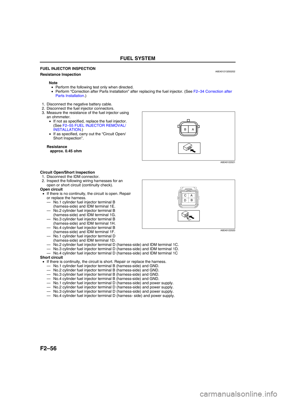
3. Measure the resistance of the fuel injector using
an ohmmeter.
•If not as specified, replace the fuel injector.
(See F2–55 FUEL INJECTOR REMOVAL/
INSTALLATION.)
•If as specified, carry out the “Circuit Open/
Short Inspection”.
Resistance
approx. 0.45 ohm
Circuit Open/Short Inspection
1. Disconnect the IDM connector.
2. Inspect the following wiring harnesses for an
open or short circuit (continuity check).
Open circuit
•If there is no continuity, the circuit is open. Repair
or replace the harness.
—No.1 cylinder fuel injector terminal B
(harness-side) and IDM terminal 1E.
—No.2 cylinder fuel injector terminal B
(harness-side) and IDM terminal 1G.
—No.3 cylinder fuel injector terminal B
(harness-side) and IDM terminal 1H.
—No.4 cylinder fuel injector terminal B
(harness-side) and IDM terminal 1F.
—No.1 cylinder fuel injector terminal D
(harness-side) and IDM terminal 1D.
—No.2 cylinder fuel injector terminal D (harness-side) and IDM terminal 1C.
—No.3 cylinder fuel injector terminal D (harness-side) and IDM terminal 1D.
—No.4 cylinder fuel injector terminal D (harness-side) and IDM terminal 1C
Short circuit
•If there is continuity, the circuit is short. Repair or replace the harness.
—No.1 cylinder fuel injector terminal B (harness-side) and GND.
—No.2 cylinder fuel injector terminal B (harness-side) and GND.
—No.3 cylinder fuel injector terminal B (harness-side) and GND.
—No.4 cylinder fuel injector terminal B (harness-side) and GND.
—No.1 cylinder fuel injector terminal D (harness-side) and power supply.
—No.2 cylinder fuel injector terminal D (harness-side) and power supply.
—No.3 cylinder fuel injector terminal D (harness-side) and power supply.
—No.4 cylinder fuel injector terminal D (harness- side) and power supply.
End Of Sie
A B
A6E40122021
A
B C
D
A6E40122020
Page 212 of 909
F2–60
EMISSION SYSTEM
EGR SOLENOID VALVE (VACUUM) INSPECTIONA6E401618741201
Note
•Perform the following inspection only when directed.
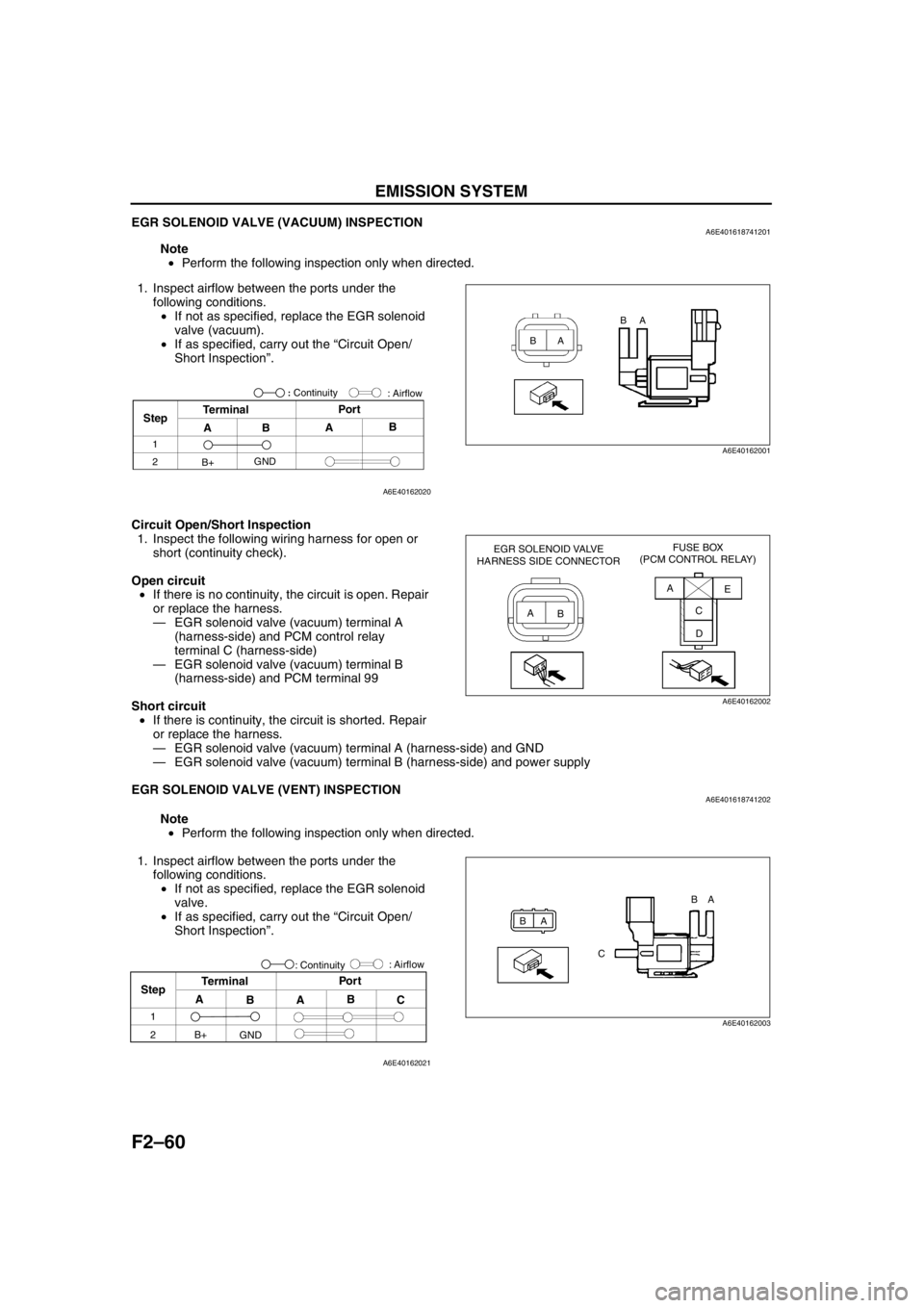
1. Inspect airflow between the ports under the
following conditions.
•If not as specified, replace the EGR solenoid
valve (vacuum).
•If as specified, carry out the “Circuit Open/
Short Inspection”.
Circuit Open/Short Inspection
1. Inspect the following wiring harness for open or
short (continuity check).
Open circuit
•If there is no continuity, the circuit is open. Repair
or replace the harness.
—EGR solenoid valve (vacuum) terminal A
(harness-side) and PCM control relay
terminal C (harness-side)
—EGR solenoid valve (vacuum) terminal B
(harness-side) and PCM terminal 99
Short circuit
•If there is continuity, the circuit is shorted. Repair
or replace the harness.
—EGR solenoid valve (vacuum) terminal A (harness-side) and GND
—EGR solenoid valve (vacuum) terminal B (harness-side) and power supply
End Of Sie
EGR SOLENOID VALVE (VENT) INSPECTIONA6E401618741202
Note
•Perform the following inspection only when directed.
1. Inspect airflow between the ports under the
following conditions.
•If not as specified, replace the EGR solenoid
valve.
•If as specified, carry out the “Circuit Open/
Short Inspection”.
BAA B
A6E40162001
StepTerminal
ABAB Por t
1
2
B+GND: Airflow
: Continuity
A6E40162020
EGR SOLENOID VALVE
HARNESS SIDE CONNECTORFUSE BOX
(PCM CONTROL RELAY)
A
BA
E
C
D
A6E40162002
BA
CBA
A6E40162003
Step
1
2
A
BAB
C Por t
Terminal
: Airflow
B+
GND: Continuity
A6E40162021
Page 213 of 909
EMISSION SYSTEM
F2–61
F2
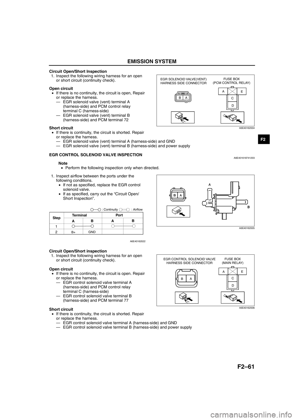
Circuit Open/Short Inspection
1. Inspect the following wiring harness for an open
or short circuit (continuity check).
Open circuit
•If there is no continuity, the circuit is open, Repair
or replace the harness.
—EGR solenoid valve (vent) terminal A
(harness-side) and PCM control relay
terminal C (harness-side)
—EGR solenoid valve (vent) terminal B
(harness-side) and PCM terminal 72
Short circuit
•If there is continuity, the circuit is shorted. Repair
or replace the harness.
—EGR solenoid valve (vent) terminal A (harness-side) and GND
—EGR solenoid valve (vent) terminal B (harness-side) and power supply
End Of Sie
EGR CONTROL SOLENOID VALVE INSPECTIONA6E401618741203
Note
•Perform the following inspection only when directed.
1. Inspect airflow between the ports under the
following conditions.
•If not as specified, replace the EGR control
solenoid valve.
•If as specified, carry out the “Circuit Open/
Short Inspection”.
Circuit Open/Short inspection
1. Inspect the following wiring harness for an open
or short circuit (continuity check).
Open circuit
•If there is no continuity, the circuit is open. Repair
or replace the harness.
—EGR control solenoid valve terminal A
(harness-side) and PCM control relay
terminal C (harness-side)
—EGR control solenoid valve terminal B
(harness-side) and PCM terminal 77
Short circuit
•If there is continuity, the circuit is shorted. Repair
or replace the harness.
—EGR control solenoid valve terminal A (harness-side) and GND
—EGR control solenoid valve terminal B (harness-side) and power supply
End Of Sie
EGR SOLENOID VALVE(VENT)
HARNESS SIDE CONNECTORFUSE BOX
(PCM CONTROL RELAY)
BAA
C
DE
A6E40162004
B
AA
B
A6E40162005
StepTerminalPor t
: Airflow
ABAB
GND
B+
1
2
: Continuity
A6E40162022
EGR CONTROL SOLENOID VALVE
HARNESS SIDE CONNECTORFUSE BOX
(MAIN RELAY)
BAAE
C
D
A6E40162006
Page 215 of 909
EMISSION SYSTEM
F2–63
F2
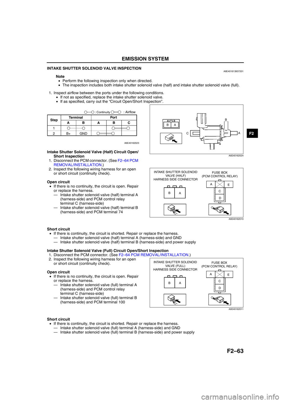
INTAKE SHUTTER SOLENOID VALVE INSPECTIONA6E401613937201
Note
•Perform the following inspection only when directed.
•The inspection includes both intake shutter solenoid valve (half) and intake shutter solenoid valve (full).
1. Inspect airflow between the ports under the following conditions.
•If not as specified, replace the intake shutter solenoid valve.
•If as specified, carry out the “Circuit Open/Short Inspection”.
Intake Shutter Solenoid Valve (Half) Circuit Open/
Short Inspection
1. Disconnect the PCM connector. (See F2–64 PCM
REMOVAL/INSTALLATION.)
2. Inspect the following wiring harness for an open
or short circuit (continuity check).
Open circuit
•If there is no continuity, the circuit is open. Repair
or replace the harness.
—Intake shutter solenoid valve (half) terminal A
(harness-side) and PCM control relay
terminal C (harness-side)
—Intake shutter solenoid valve (half) terminal B
(harness-side) and PCM terminal 74
Short circuit
•If there is continuity, the circuit is shorted. Repair or replace the harness.
—Intake shutter solenoid valve (half) terminal A (harness-side) and GND
—Intake shutter solenoid valve (half) terminal B (harness-side) and power supply
Intake Shutter Solenoid Valve (Full) Circuit Open/Short Inspection
1. Disconnect the PCM connector. (See F2–64 PCM REMOVAL/INSTALLATION.)
2. Inspect the following wiring harness for an open
or short circuit (continuity check).
Open circuit
•If there is no continuity, the circuit is open. Repair
or replace the harness.
—Intake shutter solenoid valve (full) terminal A
(harness-side) and PCM control relay
terminal C (harness-side)
—Intake shutter solenoid valve (full) terminal B
(harness-side) and PCM terminal 100
Short circuit
•If there is continuity, the circuit is shorted. Repair or replace the harness.
—Intake shutter solenoid valve (full) terminal A (harness-side) and GND
—Intake shutter solenoid valve (full) terminal B (harness-side) and power supply
End Of Sie
B
A
CB
A
A6E40162024
StepTerminal
C B
A B APor t: Airflow
1
2B+ GND
: Continuity
A6E40162023
INTAKE SHUTTER SOLENOID
VALVE (HALF)
HARNESS SIDE CONNECTORFUSE BOX
(PCM CONTROL RELAY)
B
AA
E
C
D
A6E40162010
INTAKE SHUTTER SOLENOID
VALVE (FULL)
HARNESS SIDE CONNECTORFUSE BOX
(PCM CONTROL RELAY)
B
AA
C
DE
A6E40162011
Page 220 of 909
F2–68
CONTROL SYSTEM
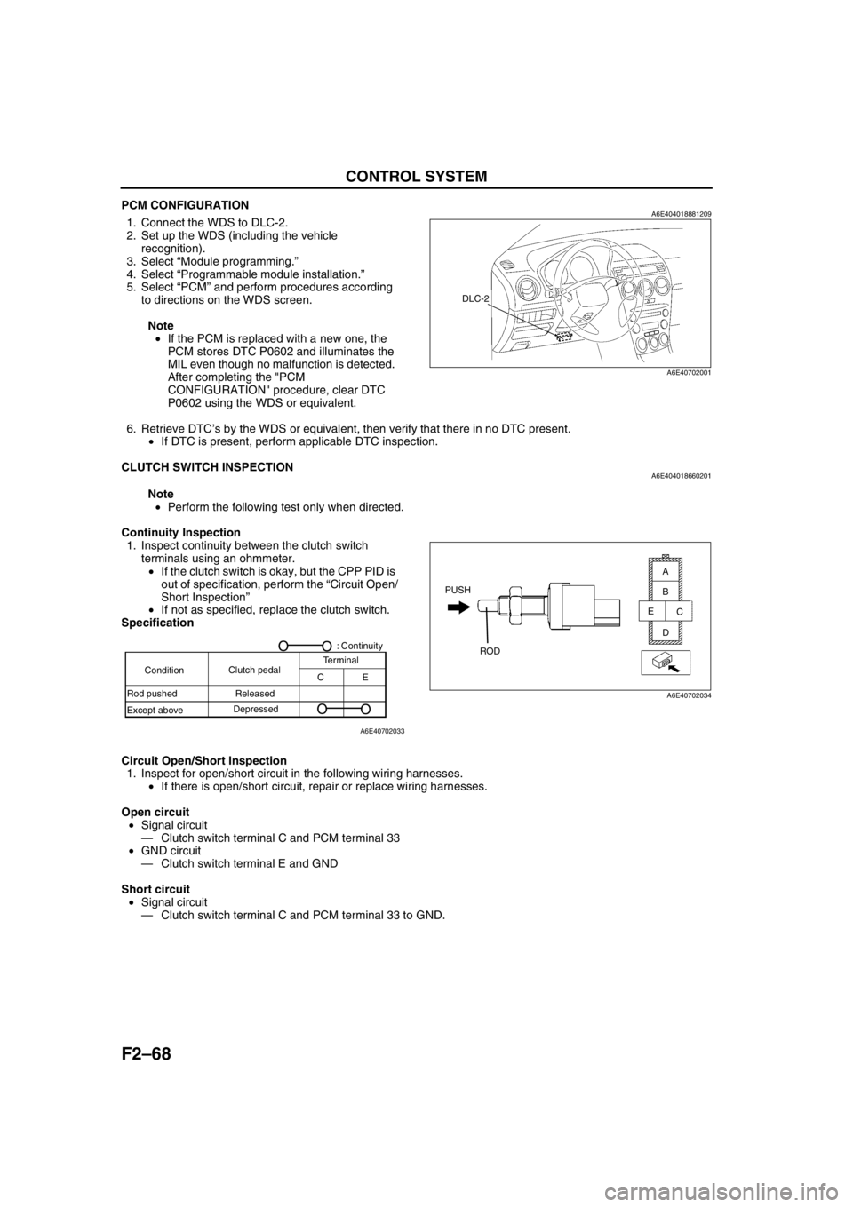
PCM CONFIGURATIONA6E4040188812091. Connect the WDS to DLC-2.
2. Set up the WDS (including the vehicle
recognition).
3. Select “Module programming.”
4. Select “Programmable module installation.”
5. Select “PCM” and perform procedures according
to directions on the WDS screen.
Note
•If the PCM is replaced with a new one, the
PCM stores DTC P0602 and illuminates the
MIL even though no malfunction is detected.
After completing the "PCM
CONFIGURATION" procedure, clear DTC
P0602 using the WDS or equivalent.
6. Retrieve DTC’s by the WDS or equivalent, then verify that there in no DTC present.
•If DTC is present, perform applicable DTC inspection.
End Of Sie
CLUTCH SWITCH INSPECTIONA6E404018660201
Note
•Perform the following test only when directed.
Continuity Inspection
1. Inspect continuity between the clutch switch
terminals using an ohmmeter.
•If the clutch switch is okay, but the CPP PID is
out of specification, perform the “Circuit Open/
Short Inspection”
•If not as specified, replace the clutch switch.
Specification
Circuit Open/Short Inspection
1. Inspect for open/short circuit in the following wiring harnesses.
•If there is open/short circuit, repair or replace wiring harnesses.
Open circuit
•Signal circuit
—Clutch switch terminal C and PCM terminal 33
•GND circuit
—Clutch switch terminal E and GND
Short circuit
•Signal circuit
—Clutch switch terminal C and PCM terminal 33 to GND.
End Of Sie
DLC-2
A6E40702001
PUSH
ROD
A
B
C
D E
A6E40702034
A6E40702033
ConditionClutch pedalTerminal
CE
Rod pushed
Except aboveReleased
Depressed
O
O
O
O: Continuity
Page 221 of 909

CONTROL SYSTEM
F2–69
F2
NEUTRAL SWITCH INSPECTIONA6E404017640201
Note
•Perform the following test only when directed.
Continuity Inspection
1. Inspect for continuity between the neutral switch
terminals using an ohmmeter.
•If the neutral switch is okay, but the CPP/PNP
PID is out of specification, perform the “Circuit
Open/Short Inspection”
•If not as specified, replace the neutral switch.
Specification
Circuit Open/Short Inspection
1. Inspect for open/short circuit in the following wiring harnesses.
•If there is open/short circuit, repair or replace wiring harnesses.
Open circuit
•Signal circuit
—Neutral switch terminal A and PCM terminal 56
•GND circuit
—Neutral switch terminal B and GND
Short circuit
•Signal circuit
—Neutral switch terminal A and PCM terminal 56 to GND
End Of Sie
PUSH
RODB
A
A6E40702036
Condition
TransmissionTerminal
O
O: Continuity
A
B
Rod pushed
Except aboveIn neutral
Other
O
O
A6E40702035
Page 222 of 909

F2–70
CONTROL SYSTEM
IDLE SWITCH INSPECTIONA6E404041600201
Note
•Perform the following test only when directed.
1. Verify that the accelerator position sensor is normal.
2. Visually inspect all accelerator pedal components for looseness.
3. Verify that the idle switch is installed to the accelerator pedal properly.
4. Verify that the power circuit voltage.
(1) Verify that the voltage between the PCM terminals 90 (power circuit) and 91(GND circuit) is 4.75—5.25 V.
Note
•Voltage at the PCM terminal 10 may deviate when the power circuit voltage is abnormal.
5. Verify that the voltage at the PCM terminal 31
(idle signal) is 1 V or less with the accelerator
pedal fully released.
6. Depress the accelerator pedal gradually and hold
the pedal when the PCM terminal 31 voltage
changes to approximately 10 V.
7. Verify that the voltage between the PCM
terminals 10 (accelerator position detection
signal) and 91 is within the specification.
•If the circuit is okay, replace the idle switch.
Specification
0.85—1.15 V (Target value: 1.0 V)
Circuit Open/Short Inspection
1. Inspect for open/short circuit in the following
wiring harnesses.
•If there is open/short circuit, repair or replace
wiring harnesses.
Open circuit
•Signal circuit
—Idle switch terminal A and PCM terminal 31
•GND circuit
—Idle switch terminal B and GND
Short circuit
•Signal circuit
—Idle switch terminal A and PCM terminal 31 to
GND
End Of Sie
ACCELERATOR POSITION SENSOR
IDLE SWITCHPCM B
A
C
D
A
B31 10
90
88
91
A6E40702037
IDLE SWITCH
HARNESS SIDE CONNECTOR
A
B
A6E40702038
Page 224 of 909

F2–72
CONTROL SYSTEM
ACCELERATOR POSITION SENSOR INSPECTIONA6E404041602201
Note
•Perform the following test only when directed.
1. Visually inspect all accelerator pedal components for looseness.
2. Verify that the accelerator position sensor is installed to the accelerator pedal properly.
3. Verify the power circuit voltage.
(1) Verify that the voltage between the PCM terminal 90 (power circuit) and 91 (GND circuit) is 4.75—5.25 V.
Note
•Voltage at the PCM terminal 10 may deviate when the power circuit voltage is abnormal.
4. Verify that the voltage between the PCM
terminals 10 (accelerator position detection
signal) and 91 is as shown below according to the
accelerator pedal conditions.
•If the circuit is okay, replace the accelerator
position sensor.
Specification
Circuit Open/Short Inspection
1. Inspect for open/short circuit in the following
wiring harnesses.
•If there is open/short circuit, repair or replace
wiring harnesses.
Open circuit
•Power circuit
—Accelerator position sensor terminal A and
PCM terminal 90
•Signal circuit
—Accelerator position sensor terminal B and
PCM terminal 10
—Accelerator position sensor terminal C and
PCM terminal 88
•GND circuit
—Accelerator position sensor terminal D and PCM terminal 91
Short circuit
•Power circuit
—Accelerator position sensor terminal A and PCM terminal 90 to GND
•Signal circuit
—Accelerator position sensor terminal B and PCM terminal 10 to power circuit
—Accelerator position sensor terminal B and PCM terminal 10 to GND
—Accelerator position sensor terminal C and PCM terminal 88 to power circuit
—Accelerator position sensor terminal C and PCM terminal 88 to GND
End Of Sie
Accelerator pedal
conditionOutput voltage (V)
Fully released 0.45—0.75 (Target value: 0.6)
Gradually depressed Increases linearly
Fully depressed 3.35—4.03 (Target value: 3.6)
ACCELERATOR POSITION SENSOR
PCM
B
A
C
D10
90
88
91
A6E40702041
ACCELERATOR POSITION SENSOR
HARNESS SIDE CONNECTOR
A B
C D
A6E40702042