MAZDA 6 2002 Workshop Manual Suplement
Manufacturer: MAZDA, Model Year: 2002, Model line: 6, Model: MAZDA 6 2002Pages: 909, PDF Size: 17.16 MB
Page 461 of 909
K2–46
AUTOMATIC TRANSAXLE
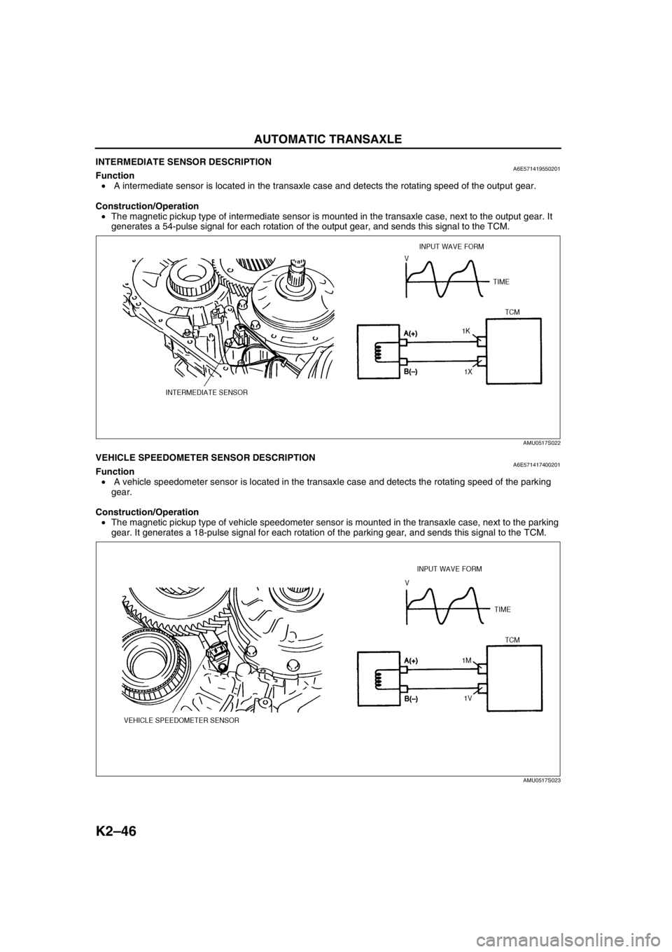
INTERMEDIATE SENSOR DESCRIPTIONA6E571419550201Function
• A intermediate sensor is located in the transaxle case and detects the rotating speed of the output gear.
Construction/Operation
•The magnetic pickup type of intermediate sensor is mounted in the transaxle case, next to the output gear. It
generates a 54-pulse signal for each rotation of the output gear, and sends this signal to the TCM.
End Of SieVEHICLE SPEEDOMETER SENSOR DESCRIPTIONA6E571417400201Function
• A vehicle speedometer sensor is located in the transaxle case and detects the rotating speed of the parking
gear.
Construction/Operation
•The magnetic pickup type of vehicle speedometer sensor is mounted in the transaxle case, next to the parking
gear. It generates a 18-pulse signal for each rotation of the parking gear, and sends this signal to the TCM.
End Of Sie
AMU0517S022
AMU0517S023
Page 462 of 909
AUTOMATIC TRANSAXLE
K2–47
K2
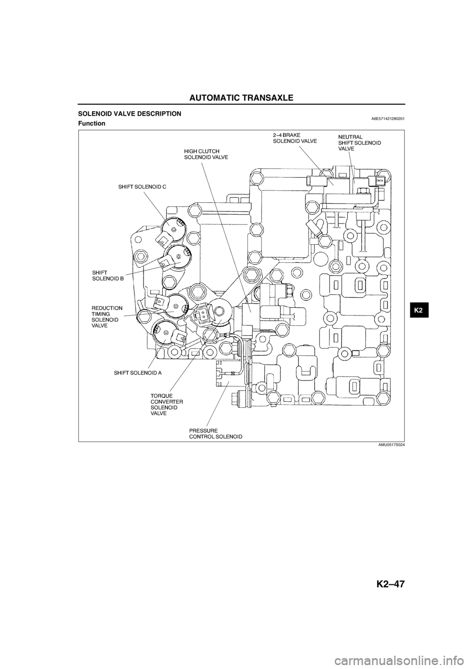
SOLENOID VALVE DESCRIPTIONA6E571421280201Function
AMU0517S024
Page 463 of 909
K2–48
AUTOMATIC TRANSAXLE
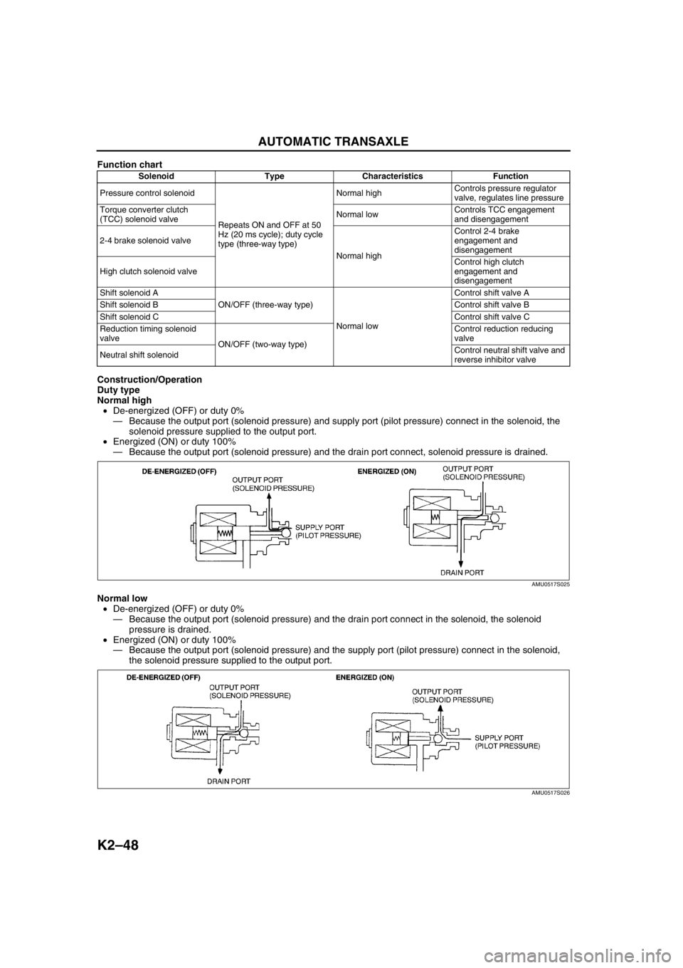
Function chart
Construction/Operation
Duty type
Normal high
•De-energized (OFF) or duty 0%
—Because the output port (solenoid pressure) and supply port (pilot pressure) connect in the solenoid, the
solenoid pressure supplied to the output port.
•Energized (ON) or duty 100%
—Because the output port (solenoid pressure) and the drain port connect, solenoid pressure is drained.
Normal low
•De-energized (OFF) or duty 0%
—Because the output port (solenoid pressure) and the drain port connect in the solenoid, the solenoid
pressure is drained.
•Energized (ON) or duty 100%
—Because the output port (solenoid pressure) and the supply port (pilot pressure) connect in the solenoid,
the solenoid pressure supplied to the output port.
Solenoid Type Characteristics Function
Pressure control solenoid
Repeats ON and OFF at 50
Hz (20 ms cycle); duty cycle
type (three-way type)Normal highControls pressure regulator
valve, regulates line pressure
Torque converter clutch
(TCC) solenoid valveNormal lowControls TCC engagement
and disengagement
2-4 brake solenoid valve
Normal highControl 2-4 brake
engagement and
disengagement
High clutch solenoid valveControl high clutch
engagement and
disengagement
Shift solenoid A
ON/OFF (three-way type)
Normal lowControl shift valve A
Shift solenoid BControl shift valve B
Shift solenoid CControl shift valve C
Reduction timing solenoid
valve
ON/OFF (two-way type)Control reduction reducing
valve
Neutral shift solenoidControl neutral shift valve and
reverse inhibitor valve
AMU0517S025
AMU0517S026
Page 464 of 909
AUTOMATIC TRANSAXLE
K2–49
K2
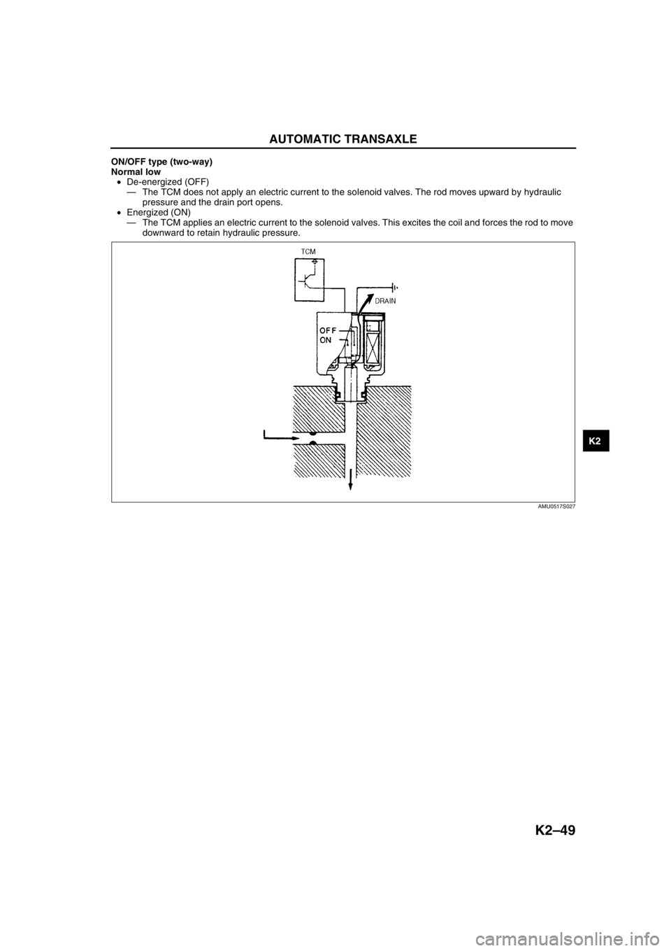
ON/OFF type (two-way)
Normal low
•De-energized (OFF)
—The TCM does not apply an electric current to the solenoid valves. The rod moves upward by hydraulic
pressure and the drain port opens.
•Energized (ON)
—The TCM applies an electric current to the solenoid valves. This excites the coil and forces the rod to move
downward to retain hydraulic pressure.
End Of Sie
AMU0517S027
Page 465 of 909

K2–50
AUTOMATIC TRANSAXLE
CONTROLLER AREA NETWORK (CAN) DESCRIPTIONA6E571418901201Outline
•The TCM transmits/receives information using the CAN system. See Section T for detailed information
regarding the CAN system.
Structure/Operation
•The PCM inputs throttle opening angle, engine speed, engine torque, engine coolant temperature. to the TCM.
•The TCM operates shift and TCC controls based on the throttle opening angle, and controls line pressure and
other based on the throttle opening angle and the engine torque.
•The TCM outputs reduce torque signal, range signal, turbine speed, ATF temperature signal, and TCC signal to
the PCM.
•If there is an open or short circuit in the CAN wiring, the system determines that the CAN is abnormal and
switches to fail-safe mode.
Input
•Throttle position
•Engine torque (without torque down)
•Engine torque (with torque down)
•Engine torque (loss torque)
•Torque reduction request
•ECT
•Engine speed
•Buttery reconnection
Output
•Range position
•Turbine speed
•ATF temperature
•TCC
•Racing select
•Gear position
•Desired torque
•Desired gear position
•Upper torque limit
•Traveled distance
•MIL indicate request
•AT warning light indicate request
End Of Sie
Page 466 of 909
AUTOMATIC TRANSAXLE
K2–51
K2
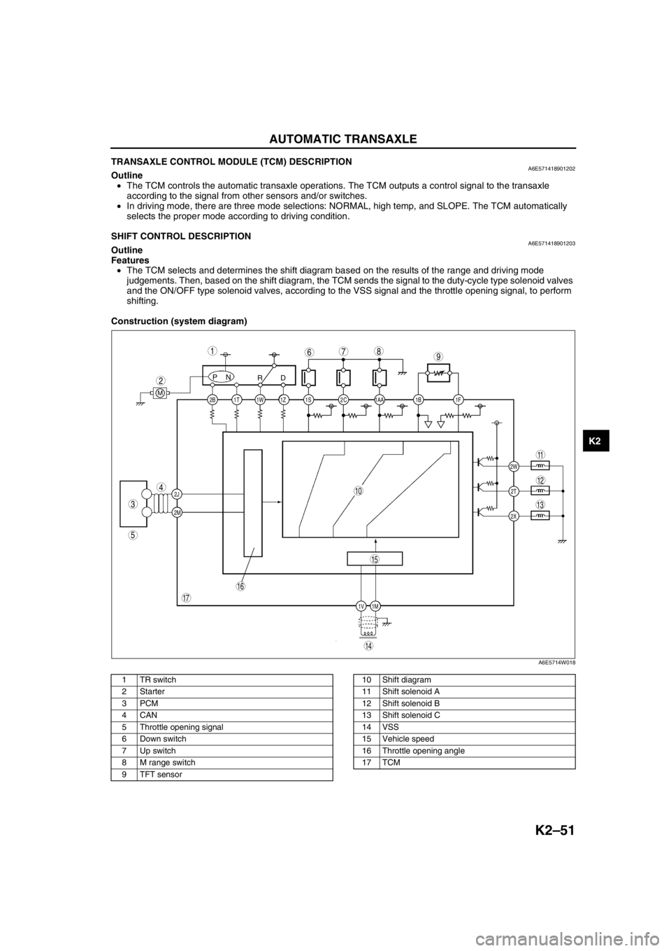
TRANSAXLE CONTROL MODULE (TCM) DESCRIPTIONA6E571418901202Outline
•The TCM controls the automatic transaxle operations. The TCM outputs a control signal to the transaxle
according to the signal from other sensors and/or switches.
•In driving mode, there are three mode selections: NORMAL, high temp, and SLOPE. The TCM automatically
selects the proper mode according to driving condition.
End Of Sie
SHIFT CONTROL DESCRIPTIONA6E571418901203Outline
Features
•The TCM selects and determines the shift diagram based on the results of the range and driving mode
judgements. Then, based on the shift diagram, the TCM sends the signal to the duty-cycle type solenoid valves
and the ON/OFF type solenoid valves, according to the VSS signal and the throttle opening signal, to perform
shifting.
Construction (system diagram)
.
2C 2B
2J
2M1AA 1S 1T 1Z1W 1B 1F
2W
1M 1V2T
2X
PN
RD
M
987
5
4
3
1
2
10
17
15
16
14
13
11
12
6
A6E5714W018
1 TR switch
2Starter
3PCM
4CAN
5 Throttle opening signal
6 Down switch
7 Up switch
8 M range switch
9 TFT sensor10 Shift diagram
11 Shift solenoid A
12 Shift solenoid B
13 Shift solenoid C
14 VSS
15 Vehicle speed
16 Throttle opening angle
17 TCM
Page 467 of 909
K2–52
AUTOMATIC TRANSAXLE
Operation
Range determination
•Each range is determined by operating the selector lever, and switching ON/OFF the switch in the TR switch
internal circuit. The present range is detected according to the ON/OFF signal of the switch.
•The following switches are built into the TR switch, and determine each range when the switch is on.
P position switch
R position switch
N position switch
D range switch
End Of Sie
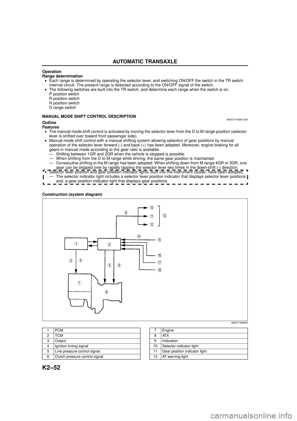
MANUAL MODE SHIFT CONTROL DESCRIPTIONA6E571418901204Outline
Features
•The manual mode shift control is activated by moving the selector lever from the D to M range position (selector
lever is shifted over toward front passenger side).
•Manual mode shift control with a manual shifting system allowing selection of gear positions by manual
operation of the selector lever forward (-) and back (+) has been adopted. Moreover, engine braking for all
gears in manual mode according to the gear ratio is available.
— Shifting between 1GR and 2GR when the vehicle is stopped is possible.
— When shifting from the D to M range while driving, the same gear position is maintained.
— Consecutive shifting in the M range has been adopted. When shifting down from M range 4GR or 3GR, one
gear can be skipped over by rapidly tapping the selector lever two times in the down-shift (-) direction.
•Selector lever position and gear position indicator lights, built into the instrument cluster, have been adopted.
— The selector indicator light includes a selector lever position indicator that displays selector lever positions
and, a gear position indicator light that displays gear positions.
Construction (system diagram)
.
9
8
7
5
43
12
10
18
17
15
16
14
1311
12
6
A6E5714W065
1PCM
2TCM
3Output
4 Ignition timing signal
5 Line pressure control signal
6 Clutch pressure control signal7Engine
8ATX
9 Indication
10 Selector indicator light
11 Gear position indicator light
12 AT warning light
Page 468 of 909

AUTOMATIC TRANSAXLE
K2–53
K2
Operation
Manual mode shift
•When the selector lever is shifted over from the D to M range position, the M range switch in the selector lever
component turns on, sending a manual mode command signal to the PCM which activates the manual mode
shift control.
•When in manual mode and the selector lever is operated in the back (+) direction, the up switch in the selector
lever component is turned on and an up-shift command signal is inputted to the PCM.
—The PCM, triggered by the up-shift command signal, carries out shifting by outputting an operation signal to
the shift solenoid if the ATF temperature is not low (for 3GR only), vehicle speed is higher than the set
speed and the gear position is 3GR or lower.
•Conversely, when the selector lever is operated in the forward (-) direction, the down switch in the selector lever
component turns on, and a down-shift command signal is inputted to the PCM.
—The PCM, triggered by the down-shift command signal, carries out shifting by outputting an operation
signal to the shift solenoid if the vehicle speed is less than the set speed and the gear position is 2GR or
above.
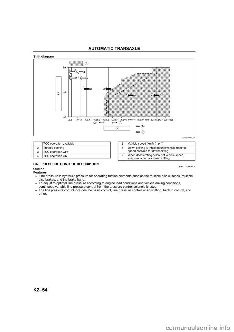
•The PCM utilizes a specialized M range automatic shift diagram when down shifting. This restriction of manual
downshifting is carried out to reduce load on the ATX and prevent engine over-revving.
13 Instrument cluster
14 Input15 Selector lever component
-M range switch
-Up switch
-Down switch
16 TR switch
17 ABS HU/CM or DSC HU/CM
18 TFT sensor
Condition Shift control Note
2GR→3GR up-shift command
at low speed•To reduce load on the ATX, upshifting is
inhibited until vehicle reaches speed
possible for upshifting
— 3GR→4GR up-shift command
at low speed
3GR→4GR up-shift command,
low ATF temperature•To reduce load on the ATX, upshifting to
4GR is inhibited
4GR→3GR down-shift
command, above set speed•To prevent engine over-rev, downshifting is
inhibited until vehicle reaches speed
possible for downshifting•Selector indicator “M” light and gear
position indicator light flash to alert
driver
3GR→2GR down-shift
command, above set speed
2GR→1GR down-shift
command, above set speed
In 4GR deceleration, speed
goes below coast-down set
speed (deceleration down-
shift)•To assure drive stability, automatically
downshifts from 4GR to 3GR
— In 3GR deceleration, speed
goes below coast-down set
speed (deceleration down-
shift)•To assure drive stability, automatically
downshifts from 3GR to 1GR
In 2GR deceleration, speed
goes below coast-down set
speed (deceleration down-
shift)•To assure driving stability, automatically
downshifts from 2GR to 1GR
Page 469 of 909
K2–54
AUTOMATIC TRANSAXLE
Shift diagram
.
End Of SieLINE PRESSURE CONTROL DESCRIPTIONA6E571418901205Outline
Features
•Line pressure is hydraulic pressure for operating friction elements such as the multiple disc clutches, multiple
disc brakes, and the brake band.
•To adjust to optimal line pressure according to engine load conditions and vehicle driving conditions,
continuous variable line pressure control from the pressure control solenoid is used.
•The line pressure control includes the basic control, line pressure control when shifting, backup control, and
other.
8/8
4/8
0/813
3
1
2 4
4
5 1
2
0{0} 20{12} 40{25} 60{37} 80{50} 100{62} 120{74} 140{87} 160{99}
180{112}200{124}
220{136}
2
3
34 4 5
7
5
43
1
2
6
A6E5714W070
1 TCC operation available
2 Throttle opening
3 TCC operation OFF
4 TCC operation ON5 Vehicle speed (km/h {mph})
6 Down shifting is inhibited until vehicle reaches
speed possible for downshifting
7 When decelerating below set vehicle speed,
executes automatic downshifting
Page 470 of 909
AUTOMATIC TRANSAXLE
K2–55
K2
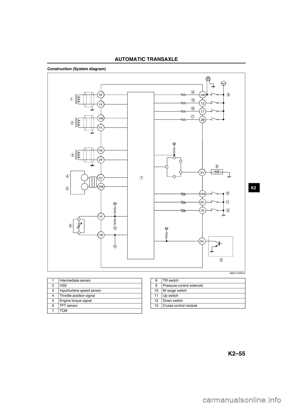
Construction (System diagram)
.
1T 1Z 1W
1AA
2C 2Y
1S
1H2B 1K
1X
1M
1V
1N
2F
2J
2M
1F
1B
9
8
7
5
4
3
1
2
10
17
15
16
14
13
11
12
6
A6E5714W019
1 Intermediate sensor
2 VSS
3 Input/turbine speed sensor
4 Throttle position signal
5 Engine torque signal
6 TFT sensor
7TCM8TR switch
9 Pressure control solenoid
10 M range switch
11 Up switch
12 Down switch
13 Cruise control module