MAZDA 6 2002 Workshop Manual Suplement
Manufacturer: MAZDA, Model Year: 2002,
Model line: 6,
Model: MAZDA 6 2002
Pages: 909, PDF Size: 17.16 MB
MAZDA 6 2002 Workshop Manual Suplement
6 2002
MAZDA
MAZDA
https://www.carmanualsonline.info/img/28/57057/w960_57057-0.png
MAZDA 6 2002 Workshop Manual Suplement
Trending: fuse box, maintenance schedule, inflation pressure, jacking, headlights, oil viscosity, jack points
Page 451 of 909
K2–36
AUTOMATIC TRANSAXLE
R position
AMU0517S058
Page 452 of 909
AUTOMATIC TRANSAXLE
K2–37
K2
AMU0517S059
Page 453 of 909
K2–38
AUTOMATIC TRANSAXLE
R position (Reverse inhibition control)
AMU0517S060
Page 454 of 909
AUTOMATIC TRANSAXLE
K2–39
K2
End Of Sie
AMU0517S061
Page 455 of 909
K2–40
AUTOMATIC TRANSAXLE
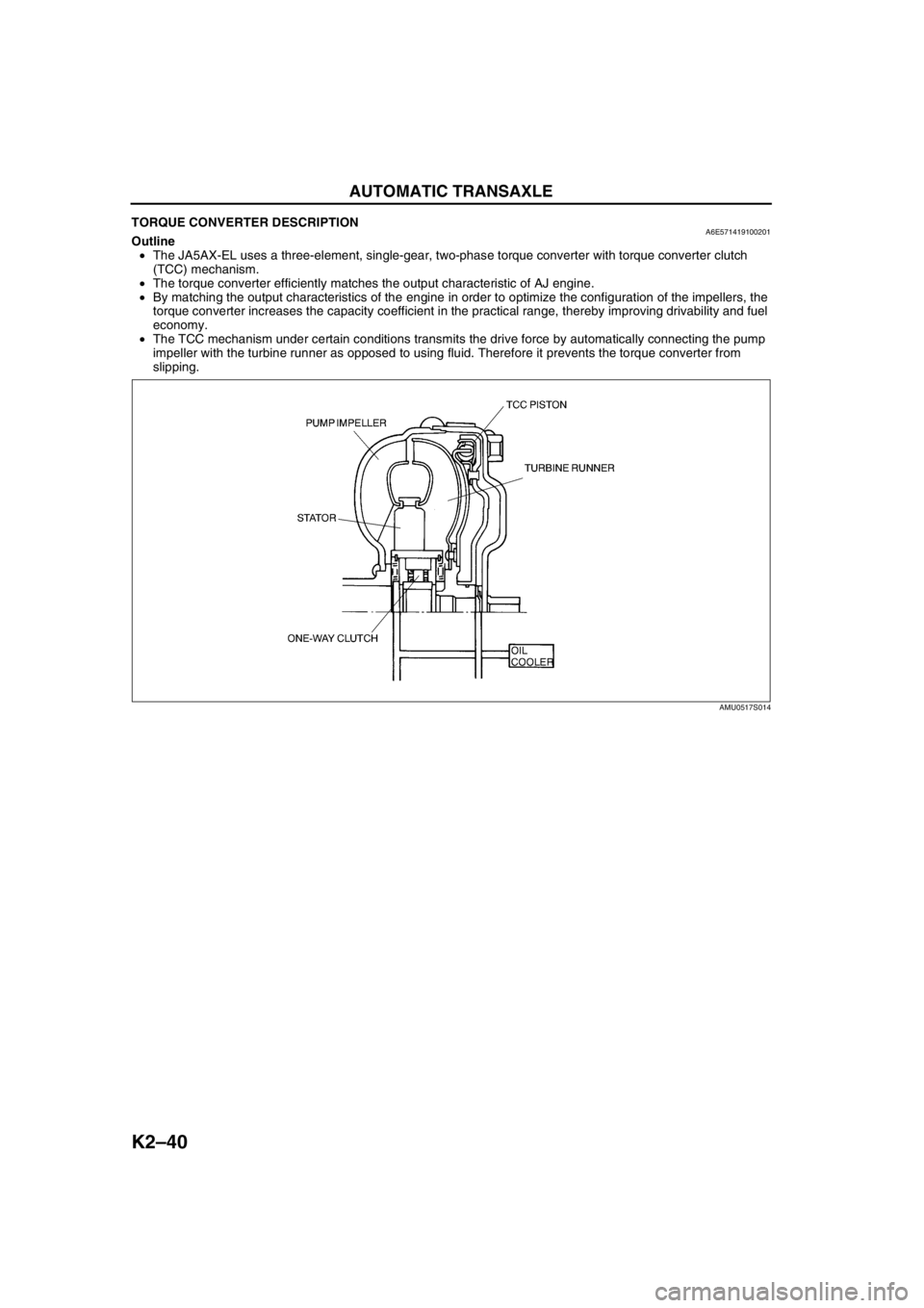
TORQUE CONVERTER DESCRIPTIONA6E571419100201Outline
•The JA5AX-EL uses a three-element, single-gear, two-phase torque converter with torque converter clutch
(TCC) mechanism.
•The torque converter efficiently matches the output characteristic of AJ engine.
•By matching the output characteristics of the engine in order to optimize the configuration of the impellers, the
torque converter increases the capacity coefficient in the practical range, thereby improving drivability and fuel
economy.
•The TCC mechanism under certain conditions transmits the drive force by automatically connecting the pump
impeller with the turbine runner as opposed to using fluid. Therefore it prevents the torque converter from
slipping.
End Of Sie
AMU0517S014
Page 456 of 909
AUTOMATIC TRANSAXLE
K2–41
K2
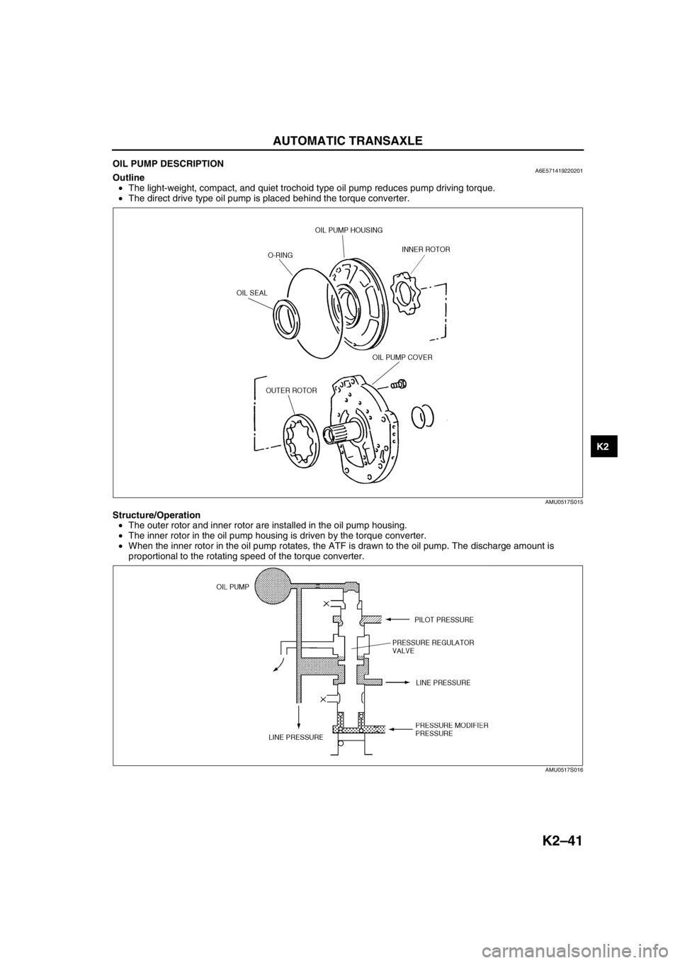
OIL PUMP DESCRIPTIONA6E571419220201Outline
•The light-weight, compact, and quiet trochoid type oil pump reduces pump driving torque.
•The direct drive type oil pump is placed behind the torque converter.
Structure/Operation
•The outer rotor and inner rotor are installed in the oil pump housing.
•The inner rotor in the oil pump housing is driven by the torque converter.
•When the inner rotor in the oil pump rotates, the ATF is drawn to the oil pump. The discharge amount is
proportional to the rotating speed of the torque converter.
End Of Sie
AMU0517S015
AMU0517S016
Page 457 of 909
K2–42
AUTOMATIC TRANSAXLE
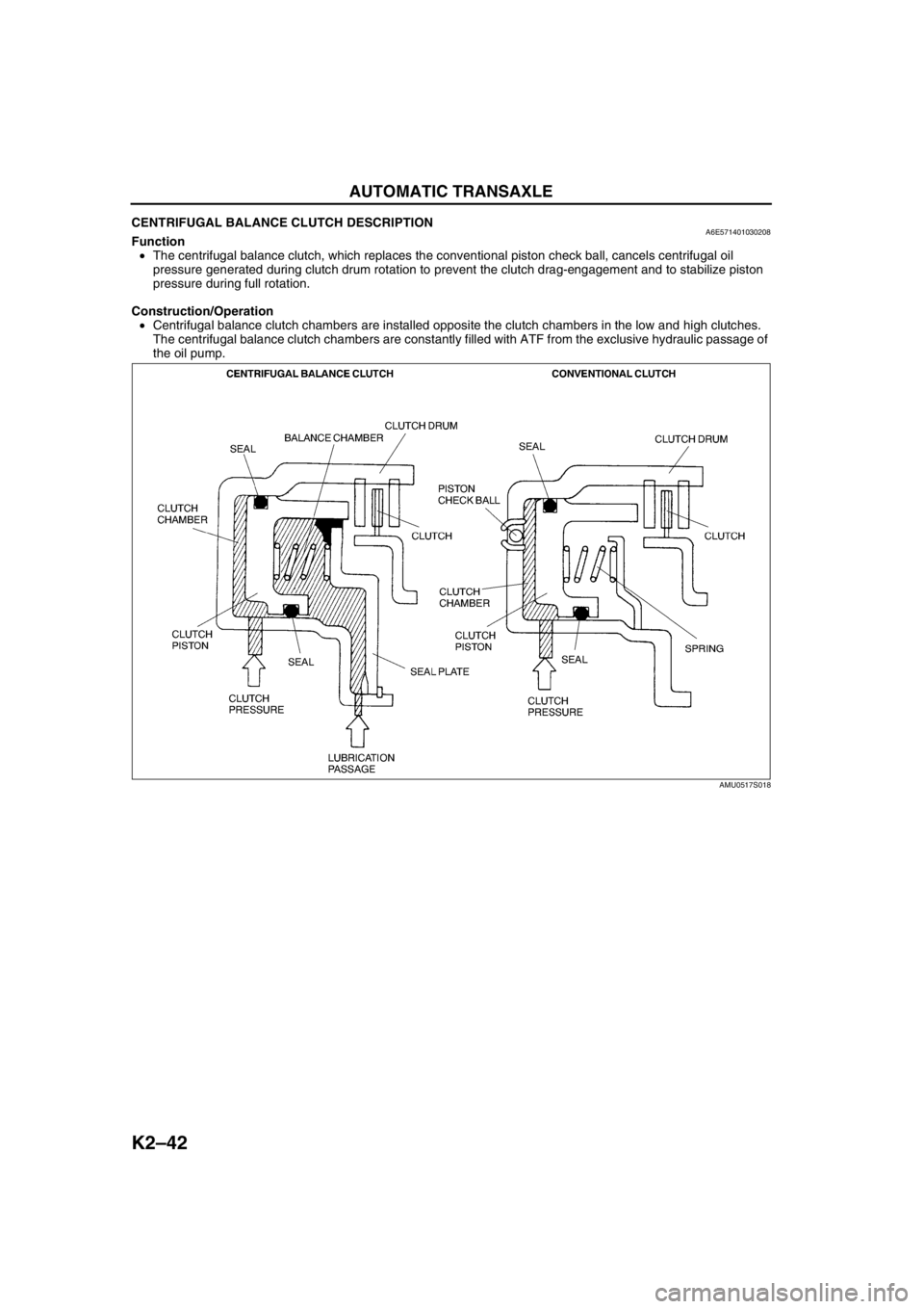
CENTRIFUGAL BALANCE CLUTCH DESCRIPTIONA6E571401030208Function
•The centrifugal balance clutch, which replaces the conventional piston check ball, cancels centrifugal oil
pressure generated during clutch drum rotation to prevent the clutch drag-engagement and to stabilize piston
pressure during full rotation.
Construction/Operation
•Centrifugal balance clutch chambers are installed opposite the clutch chambers in the low and high clutches.
The centrifugal balance clutch chambers are constantly filled with ATF from the exclusive hydraulic passage of
the oil pump.
AMU0517S018
Page 458 of 909
AUTOMATIC TRANSAXLE
K2–43
K2
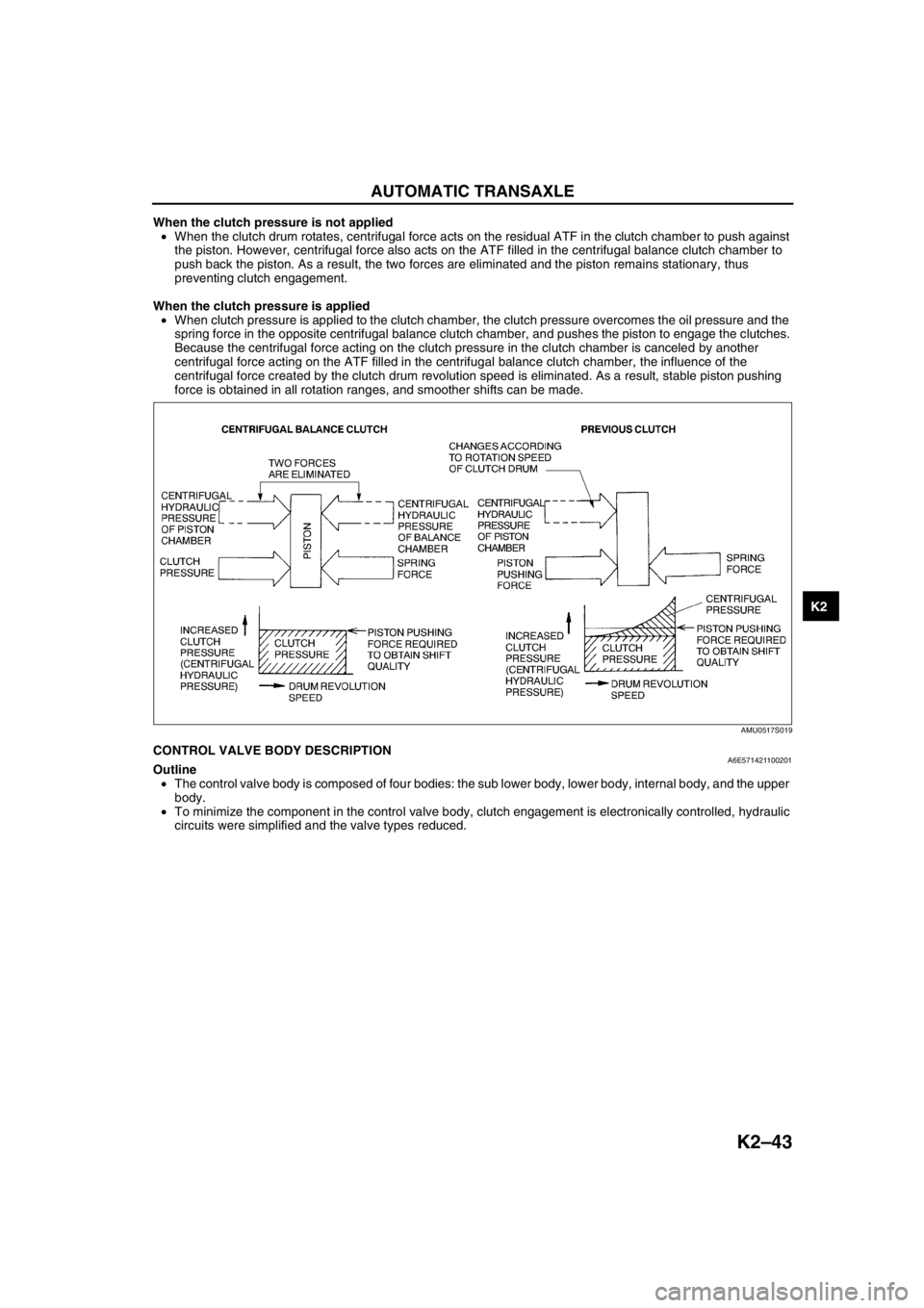
When the clutch pressure is not applied
•When the clutch drum rotates, centrifugal force acts on the residual ATF in the clutch chamber to push against
the piston. However, centrifugal force also acts on the ATF filled in the centrifugal balance clutch chamber to
push back the piston. As a result, the two forces are eliminated and the piston remains stationary, thus
preventing clutch engagement.
When the clutch pressure is applied
•When clutch pressure is applied to the clutch chamber, the clutch pressure overcomes the oil pressure and the
spring force in the opposite centrifugal balance clutch chamber, and pushes the piston to engage the clutches.
Because the centrifugal force acting on the clutch pressure in the clutch chamber is canceled by another
centrifugal force acting on the ATF filled in the centrifugal balance clutch chamber, the influence of the
centrifugal force created by the clutch drum revolution speed is eliminated. As a result, stable piston pushing
force is obtained in all rotation ranges, and smoother shifts can be made.
End Of SieCONTROL VALVE BODY DESCRIPTIONA6E571421100201Outline
•The control valve body is composed of four bodies: the sub lower body, lower body, internal body, and the upper
body.
•To minimize the component in the control valve body, clutch engagement is electronically controlled, hydraulic
circuits were simplified and the valve types reduced.
AMU0517S019
Page 459 of 909
K2–44
AUTOMATIC TRANSAXLE
End Of Sie
AMU0517S064
Page 460 of 909
AUTOMATIC TRANSAXLE
K2–45
K2
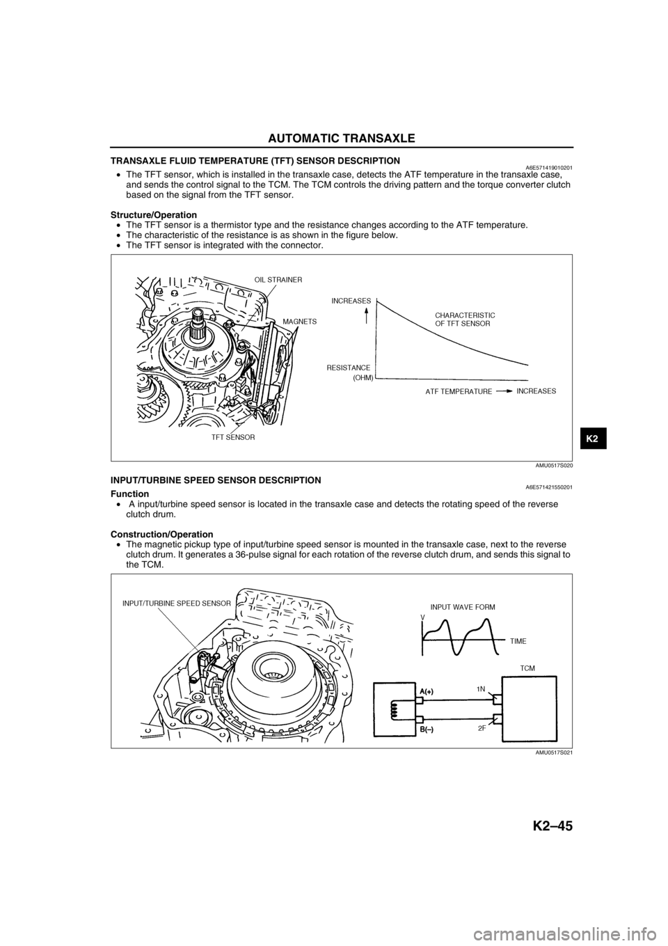
TRANSAXLE FLUID TEMPERATURE (TFT) SENSOR DESCRIPTIONA6E571419010201•The TFT sensor, which is installed in the transaxle case, detects the ATF temperature in the transaxle case,
and sends the control signal to the TCM. The TCM controls the driving pattern and the torque converter clutch
based on the signal from the TFT sensor.
Structure/Operation
•The TFT sensor is a thermistor type and the resistance changes according to the ATF temperature.
•The characteristic of the resistance is as shown in the figure below.
•The TFT sensor is integrated with the connector.
End Of SieINPUT/TURBINE SPEED SENSOR DESCRIPTIONA6E571421550201Function
• A input/turbine speed sensor is located in the transaxle case and detects the rotating speed of the reverse
clutch drum.
Construction/Operation
•The magnetic pickup type of input/turbine speed sensor is mounted in the transaxle case, next to the reverse
clutch drum. It generates a 36-pulse signal for each rotation of the reverse clutch drum, and sends this signal to
the TCM.
End Of Sie
AMU0517S020
AMU0517S021
Trending: set clock, wiring, fuel tank removal, automatic transmission fluid, fuel tank capacity, center console, brake fluid


