MAZDA 6 2002 Workshop Manual Suplement
Manufacturer: MAZDA, Model Year: 2002, Model line: 6, Model: MAZDA 6 2002Pages: 909, PDF Size: 17.16 MB
Page 511 of 909

K2–96
AUTOMATIC TRANSAXLE
TCC solenoid valve signal (lock up on)
•TCM terminal: 2S (+)—2P (–)
•Oscilloscope setting: 5 V/DIV (Y) 5 ms/DIV (X)
•Measuring condition: Drive the vehicle with lock
up
End Of SieTCM REMOVAL/INSTALLATIONA6E5714189012121. Disconnect the negative battery cable.
2. For R.H.D., perform the following procedures.
(1) Remove the front side trim (left-side).
(2) Partially peel back the flower covering.
3. Remove in the order indicated in the table.
4. Install in the reverse order of removal.
U.K. specs.
.
AMU0517W059
2
1
3
SET BOLT
7.8—10.8
{80—110 kgf·cm,
69.5—95.4 in·lbf}
SET NUT
A6E5714W123
1 Control unit bracket
2 TCM connector3TCM
Page 512 of 909
AUTOMATIC TRANSAXLE
K2–97
K2
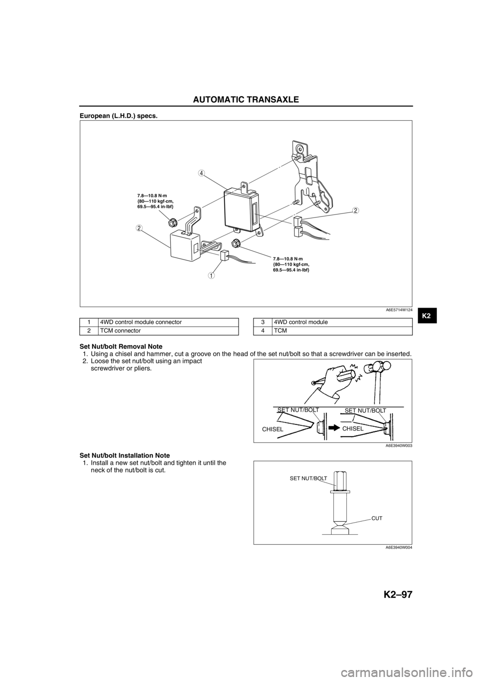
European (L.H.D.) specs.
.
Set Nut/bolt Removal Note
1. Using a chisel and hammer, cut a groove on the head of the set nut/bolt so that a screwdriver can be inserted.
2. Loose the set nut/bolt using an impact
screwdriver or pliers.
Set Nut/bolt Installation Note
1. Install a new set nut/bolt and tighten it until the
neck of the nut/bolt is cut.
2
4
7.8—10.8 N·m
{80—110 kgf·cm,
69.5—95.4 in·lbf} 7.8—10.8 N·m
{80—110 kgf·cm,
69.5—95.4 in·lbf}
2
1
A6E5714W124
1 4WD control module connector
2 TCM connector3 4WD control module
4TCM
CHISELCHISEL SET NUT/BOLT
SET NUT/BOLT
A6E3940W003
SET NUT/BOLT
CUT
A6E3940W004
Page 513 of 909

K2–98
AUTOMATIC TRANSAXLE
THIS PAGE IS
INTENTIONALLY
LEFT BLANK
End Of Sie
Page 514 of 909
AUTOMATIC TRANSAXLE
K2–99
K2
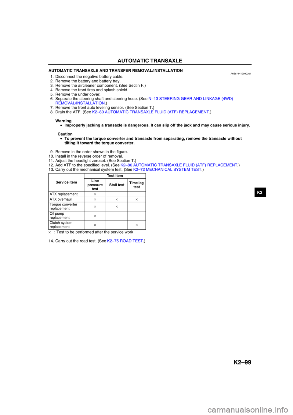
AUTOMATIC TRANSAXLE AND TRANSFER REMOVAL/INSTALLATIONA6E5714190902011. Disconnect the negative battery cable.
2. Remove the battery and battery tray.
3. Remove the aircleaner component. (See Sectin F.)
4. Remove the front tires and splash shield.
5. Remove the under cover.
6. Separate the steering shaft and steering hose. (See N–13 STEERING GEAR AND LINKAGE (4WD)
REMOVAL/INSTALLATION.)
7. Remove the front auto leveling sensor. (See Section T.)
8. Drain the ATF. (See K2–80 AUTOMATIC TRANSAXLE FLUID (ATF) REPLACEMENT.)
Warning
•Improperly jacking a transaxle is dangerous. It can slip off the jack and may cause serious injury.
Caution
•To prevent the torque converter and transaxle from separating, remove the transaxle without
tilting it toward the torque converter.
9. Remove in the order shown in the figure.
10. Install in the reverse order of removal.
11. Adjust the headlight zeroset. (See Section T.)
12. Add ATF to the specified level. (See K2–80 AUTOMATIC TRANSAXLE FLUID (ATF) REPLACEMENT.)
13. Carry out the mechanical system test. (See K2–72 MECHANICAL SYSTEM TEST.)
×: Test to be performed after the service work
14. Carry out the road test. (See K2–75 ROAD TEST.)
Service itemTest item
Line
pressure
testStall testTime lag
test
ATX replacement×
ATX overhaul×××
Torque converter
replacement××
Oil pump
replacement×
Clutch system
replacement××
Page 515 of 909

K2–100
AUTOMATIC TRANSAXLE
.
13
119.6—154.8
{12.20—15.78,
88.22—114.1}
5
6
7
24
8
17
16
9
102115
12
22
19
20
18
11
14
23
R
R
R
R
37—52
{3.8—5.3, 28—38}
42—62
{4.3—6.3, 31—45}6.9—9.8
{71—99 kgf·cm,
62—86 in·lbf}34.3—60.5
{3.50—6.16, 25.3—44.6}
66.6—93.1
{6.80—9.49, 49.2—68.6}
37—52
{3.8—5.3, 28—38}
A
4
31
2
A
B
D
D
B
C
E
C
N·m {kgf·m, ft·lbf} —
E85.3—116.6
{8.70—11.88,
62.91—85.98}85.3—116.6
{8.70—11.88, 62.91—85.98} 93.1—126.4
{9.50—12.88,
68.67—93.22}33.0—44.1
{3.21—4.49,
23.2—32.5}
93.1—131.3
{9.50—13.38, 68.67—96.84}166.6—200.0
{16.99—20.39,
122.9—147.5} 43.1—60.8
{4.40—6.19,
31.8—44.8}
A6E5714W131
Page 516 of 909
AUTOMATIC TRANSAXLE
K2–101
K2
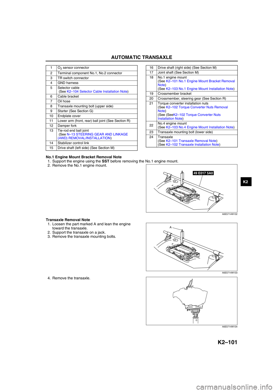
No.1 Engine Mount Bracket Removal Note
1. Support the engine using the SST before removing the No.1 engine mount.
2. Remove the No.1 engine mount.
Transaxle Removal Note
1. Loosen the part marked A and lean the engine
toward the transaxle.
2. Support the transaxle on a jack.
3. Remove the transaxle mounting bolts.
4. Remove the transaxle.
1O2 sensor connector
2 Terminal component No.1, No.2 connector
3 TR switch connector
4 GND harness
5 Selector cable
(See K2–104 Selector Cable Installation Note)
6 Cable bracket
7 Oil hose
8 Transaxle mounting bolt (upper side)
9 Starter (See Section G)
10 Endplate cover
11 Lower arm (front, rear) ball joint (See Section R)
12 Damper fork
13 Tie-rod end ball joint
(See N–13 STEERING GEAR AND LINKAGE
(4WD) REMOVAL/INSTALLATION)
14 Stabilizer control link
15 Drive shaft (left side) (See Section M)16 Drive shaft (right side) (See Section M)
17 Joint shaft (See Section M)
18 No.1 engine mount
(See K2–101 No.1 Engine Mount Bracket Removal
Note)
(See K2–103 No.1 Engine Mount Installation Note)
19 Crossmember bracket
20 Crossmember, steering gear (See Section R)
21 Torque converter installation nuts
(See K2–102 Torque Converter Nuts Removal
Note)
(See (SeeK2–102 Torque Converter Nuts
Installation Note)
22No.4 engine mount
(See K2–103 No.4 Engine Mount Installation Note)
23 Transaxle mounting bolt (lower side)
24 Transaxle
(See K2–101 Transaxle Removal Note)
(See K2–102 Transaxle Installation Note)
49 E017 5A0
A6E5714W132
A
A6E5714W133
A6E5714W134
Page 517 of 909
K2–102
AUTOMATIC TRANSAXLE
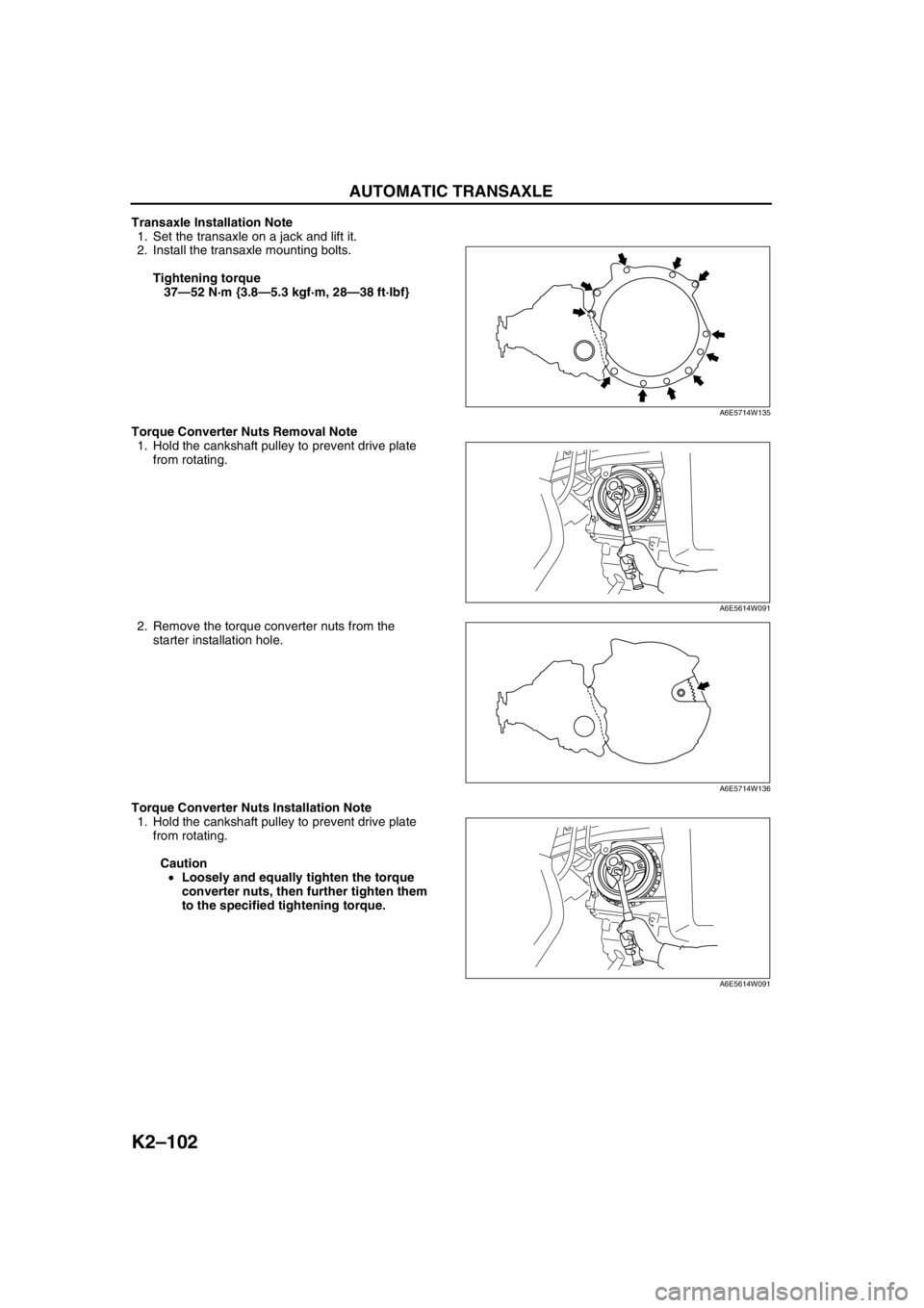
Transaxle Installation Note
1. Set the transaxle on a jack and lift it.
2. Install the transaxle mounting bolts.
Tightening torque
37—52 N·m {3.8—5.3 kgf·m, 28—38 ft·lbf}
Torque Converter Nuts Removal Note
1. Hold the cankshaft pulley to prevent drive plate
from rotating.
2. Remove the torque converter nuts from the
starter installation hole.
Torque Converter Nuts Installation Note
1. Hold the cankshaft pulley to prevent drive plate
from rotating.
Caution
•Loosely and equally tighten the torque
converter nuts, then further tighten them
to the specified tightening torque.
A6E5714W135
A6E5614W091
A6E5714W136
A6E5614W091
Page 518 of 909
AUTOMATIC TRANSAXLE
K2–103
K2
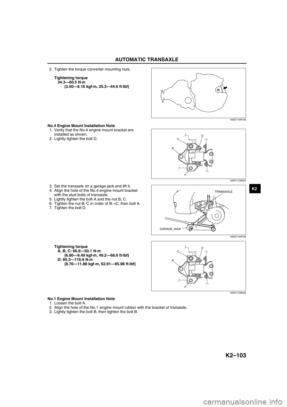
2. Tighten the torque converter mounting nuts.
Tightening torque
34.3—60.5 N·m
{3.50—6.16 kgf·m, 25.3—44.6 ft·lbf}
No.4 Engine Mount Installation Note
1. Verify that the No.4 engine mount bracket are
installed as shown.
2. Lightly tighten the bolt D.
3. Set the transaxle on a garage jack and lift it.
4. Align the hole of the No.4 engine mount bracket
with the stud bolts of transaxle.
5. Lightly tighten the bolt A and the nut B, C.
6. Tighten the nut B, C in order of B→C, then bolt A.
7. Tighten the bolt D.
8.
Tightening torque
A, B, C: 66.6—93.1 N·m
{6.80—9.49 kgf·m, 49.2—68.6 ft·lbf}
D: 85.3—116.6 N·m
{8.70—11.88 kgf·m, 62.91—85.98 ft·lbf}
No.1 Engine Mount Installation Note
1. Loosen the bolt A.
2. Align the hole of the No.1 engine mount rubber with the bracket of transaxle.
3. Lightly tighten the bolt B, then tighten the bolt B.
A6E5714W136
D
A BC
A6E5112W005
TRANSAXLE
GARAGE JACK
A6E5714W139
D
A BC
A6E5112W005
Page 519 of 909
K2–104
AUTOMATIC TRANSAXLE
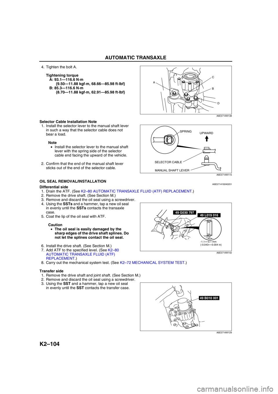
4. Tighten the bolt A.
Tightening torque
A: 93.1—116.6 N·m
{9.50—11.88 kgf·m, 68.66—85.98 ft·lbf}
B: 85.3—116.6 N·m
{8.70—11.88 kgf·m, 62.91—85.98 ft·lbf}
Selector Cable Installation Note
1. Install the selector lever to the manual shaft lever
in such a way that the selector cable does not
bear a load.
Note
•Install the selector lever to the manual shaft
lever with the spring side of the selector
cable end facing the upward of the vehicle.
2. Confirm that the end of the manual shaft lever
sticks out of the end of the selector cable.
End Of SieOIL SEAL REMOVAL/INSTALLATIONA6E571419240201Differential side
1. Drain the ATF. (See K2–80 AUTOMATIC TRANSAXLE FLUID (ATF) REPLACEMENT.)
2. Remove the drive shaft. (See Section M.)
3. Remove and discard the oil seal using a screwdriver.
4. Using the SSTs and a hammer, tap a new oil seal
in evenly until the SSTs contacts the transaxle
case.
5. Coat the lip of the oil seal with ATF.
Caution
•The oil seal is easily damaged by the
sharp edges of the drive shaft splines. Do
not let the splines contact the oil seal.
6. Install the drive shaft. (See Section M.)
7. Add ATF to the specified level. (See K2–80
AUTOMATIC TRANSAXLE FLUID (ATF)
REPLACEMENT.)
8. Carry out the mechanical system test. (See K2–72 MECHANICAL SYSTEM TEST.)
Transfer side
1. Remove the drive shaft and joint shaft. (See Section M.)
2. Remove and discard the oil seal using a screwdriver.
3. Using the SST and a hammer, tap a new oil seal
in evenly until the SST contacts the transfer case.
AC
B
D
A6E5714W138
SELECTOR CABLE
MANUAL SHAFT LEVERSPRING
UPWARD
A6E5714W115
49 G030 79749 L019 016
-1.1—-0.1 mm
{-0.043—-0.004 in}
A6E5714W142
49 B010 001
A6E5714W129
Page 520 of 909
AUTOMATIC TRANSAXLE
K2–105
K2
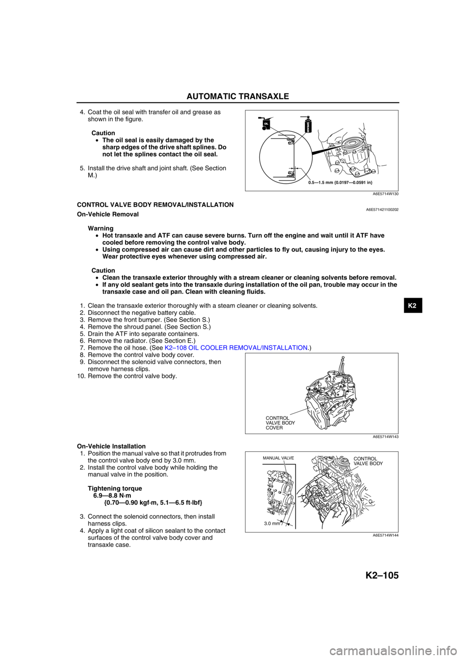
4. Coat the oil seal with transfer oil and grease as
shown in the figure.
Caution
•The oil seal is easily damaged by the
sharp edges of the drive shaft splines. Do
not let the splines contact the oil seal.
5. Install the drive shaft and joint shaft. (See Section
M.)
End Of SieCONTROL VALVE BODY REMOVAL/INSTALLATIONA6E571421100202On-Vehicle Removal
Warning
•Hot transaxle and ATF can cause severe burns. Turn off the engine and wait until it ATF have
cooled before removing the control valve body.
•Using compressed air can cause dirt and other particles to fly out, causing injury to the eyes.
Wear protective eyes whenever using compressed air.
Caution
•Clean the transaxle exterior throughly with a stream cleaner or cleaning solvents before removal.
•If any old sealant gets into the transaxle during installation of the oil pan, trouble may occur in the
transaxle case and oil pan. Clean with cleaning fluids.
1. Clean the transaxle exterior thoroughly with a steam cleaner or cleaning solvents.
2. Disconnect the negative battery cable.
3. Remove the front bumper. (See Section S.)
4. Remove the shroud panel. (See Section S.)
5. Drain the ATF into separate containers.
6. Remove the radiator. (See Section E.)
7. Remove the oil hose. (See K2–108 OIL COOLER REMOVAL/INSTALLATION.)
8. Remove the control valve body cover.
9. Disconnect the solenoid valve connectors, then
remove harness clips.
10. Remove the control valve body.
On-Vehicle Installation
1. Position the manual valve so that it protrudes from
the control valve body end by 3.0 mm.
2. Install the control valve body while holding the
manual valve in the position.
Tightening torque
6.9—8.8 N·m
{0.70—0.90 kgf·m, 5.1—6.5 ft·lbf}
3. Connect the solenoid connectors, then install
harness clips.
4. Apply a light coat of silicon sealant to the contact
surfaces of the control valve body cover and
transaxle case.
OILOIL
0.5—1.5 mm {0.0197—0.0591 in}
GREASEGREASE
A6E5714W130
CONTROL
VALVE BODY
COVER
A6E5714W143
3.0 mm
MANUAL VALVECONTROL
VALVE BODY
A6E5714W144