MAZDA 6 2002 Workshop Manual Suplement
Manufacturer: MAZDA, Model Year: 2002, Model line: 6, Model: MAZDA 6 2002Pages: 909, PDF Size: 17.16 MB
Page 521 of 909
K2–106
AUTOMATIC TRANSAXLE
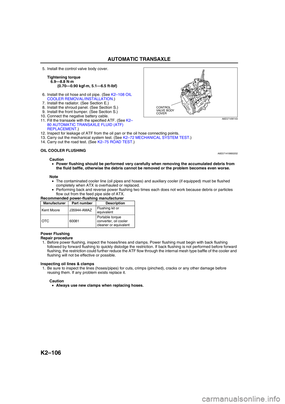
5. Install the control valve body cover.
Tightening torque
6.9—8.8 N·m
{0.70—0.90 kgf·m, 5.1—6.5 ft·lbf}
6. Install the oil hose and oil pipe. (See K2–108 OIL
COOLER REMOVAL/INSTALLATION.)
7. Install the radiator. (See Section E.)
8. Install the shroud panel. (See Section S.)
9. Install the front bumper. (See Section S.)
10. Connect the negative battery cable.
11. Fill the transaxle with the specified ATF. (See K2–
80 AUTOMATIC TRANSAXLE FLUID (ATF)
REPLACEMENT.)
12. Inspect for leakage of ATF from the oil pan or the oil hose connecting points.
13. Carry out the mechanical system test. (See K2–72 MECHANICAL SYSTEM TEST.)
14. Carry out the road test. (See K2–75 ROAD TEST.)
End Of Sie
OIL COOLER FLUSHINGA6E571419900202
Caution
•Power flushing should be performed very carefully when removing the accumulated debris from
the fluid baffle, otherwise the debris cannot be removed or the problem becomes even worse.
Note
•The contaminated cooler line (oil pipes and hoses) and auxiliary cooler (if equipped) must be flushed
completely when ATX is overhauled or replaced.
•Performing back and reverse power flushing two times each does not work because debris or particles
flow out from the feed pipe side of ATX.
Recommended power-flushing manufacturer
Power Flushing
Repair procedure
1. Before power flushing, inspect the hoses/lines and clamps. Power flushing must begin with back flushing
followed by forward flushing to quickly dislodge the restriction. If back flushing is not performed before forward
flushing, the restriction could further reduce the ATF flow through the internal mesh type baffle of the cooler and
flushing will not be effective or possible.
Inspecting oil lines & clamps
1. Be sure to inspect the lines (hoses/pipes) for cuts, crimps (pinched), cracks or any other damage before
reusing them. If any problem exists replace it.
Caution
•Always use new clamps when replacing hoses.
CONTROL
VALVE BODY
COVER
A6E5714W143
Manufacturer Part number Description
Kent Moore J35944-AMAZFlushing kit or
equivalent
OTC 60081Portable torque
converter, oil cooler
cleaner or equivalent
Page 522 of 909
AUTOMATIC TRANSAXLE
K2–107
K2
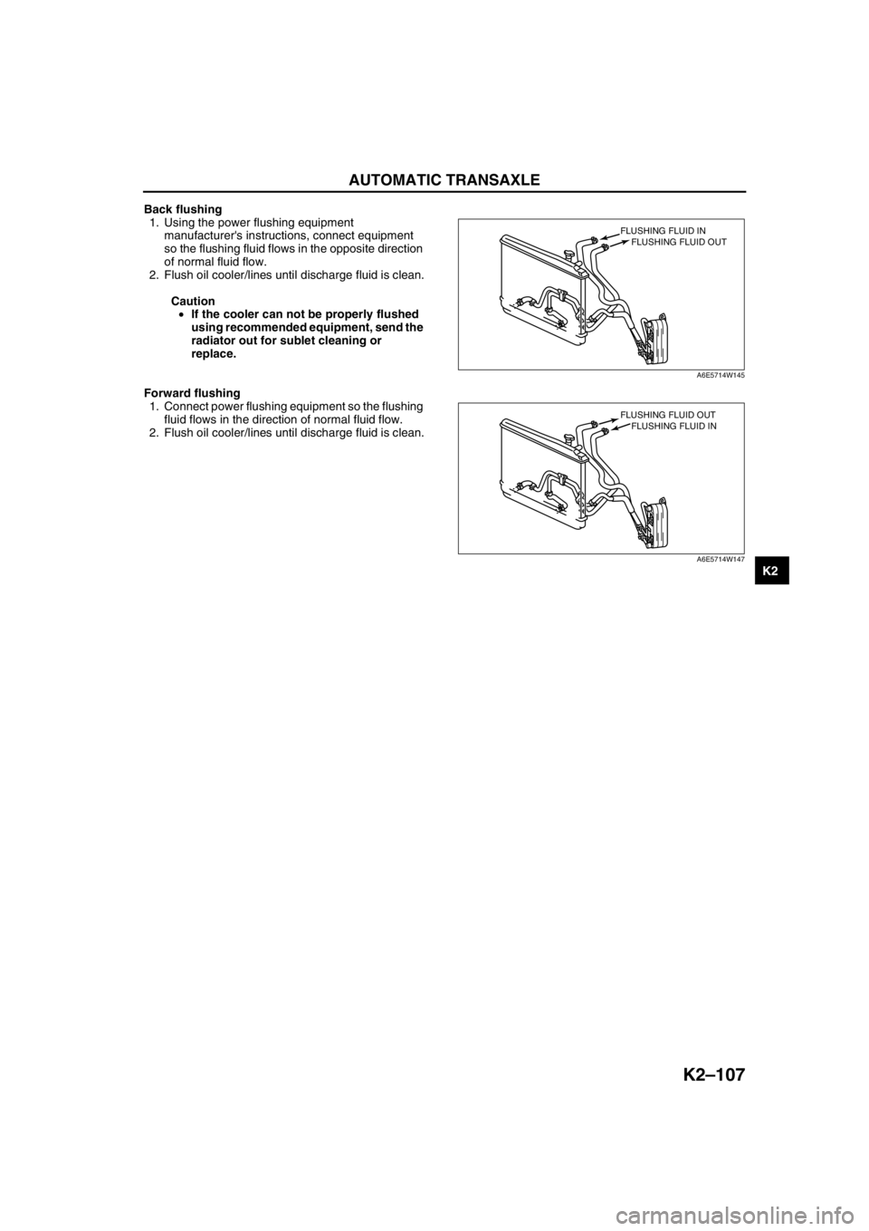
Back flushing
1. Using the power flushing equipment
manufacturer's instructions, connect equipment
so the flushing fluid flows in the opposite direction
of normal fluid flow.
2. Flush oil cooler/lines until discharge fluid is clean.
Caution
•If the cooler can not be properly flushed
using recommended equipment, send the
radiator out for sublet cleaning or
replace.
Forward flushing
1. Connect power flushing equipment so the flushing
fluid flows in the direction of normal fluid flow.
2. Flush oil cooler/lines until discharge fluid is clean.
End Of Sie
FLUSHING FLUID OUT FLUSHING FLUID IN
A6E5714W145
FLUSHING FLUID IN FLUSHING FLUID OUT
A6E5714W147
Page 523 of 909
K2–108
AUTOMATIC TRANSAXLE
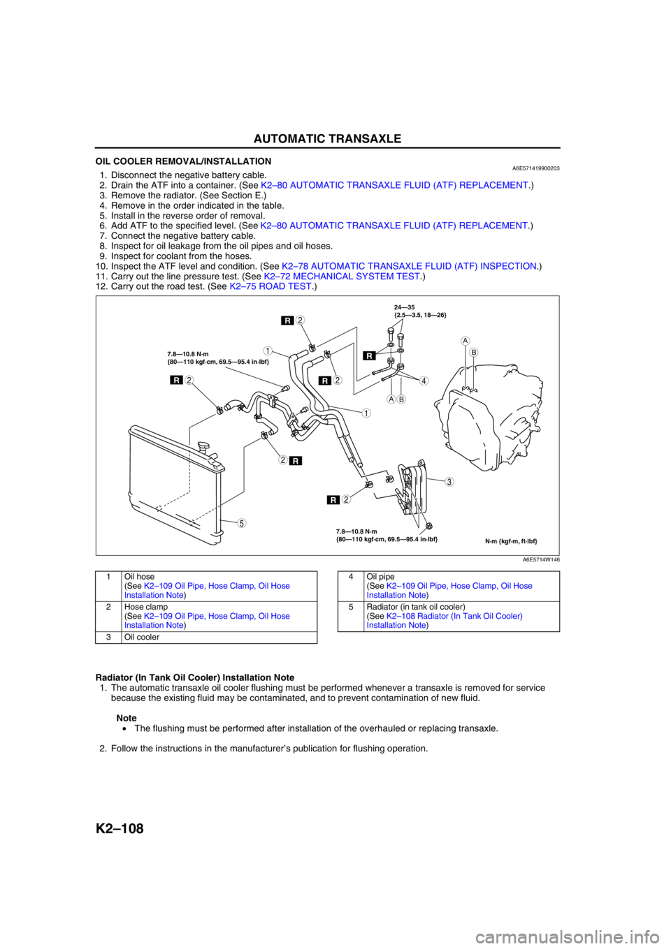
OIL COOLER REMOVAL/INSTALLATIONA6E5714199002031. Disconnect the negative battery cable.
2. Drain the ATF into a container. (See K2–80 AUTOMATIC TRANSAXLE FLUID (ATF) REPLACEMENT.)
3. Remove the radiator. (See Section E.)
4. Remove in the order indicated in the table.
5. Install in the reverse order of removal.
6. Add ATF to the specified level. (See K2–80 AUTOMATIC TRANSAXLE FLUID (ATF) REPLACEMENT.)
7. Connect the negative battery cable.
8. Inspect for oil leakage from the oil pipes and oil hoses.
9. Inspect for coolant from the hoses.
10. Inspect the ATF level and condition. (See K2–78 AUTOMATIC TRANSAXLE FLUID (ATF) INSPECTION.)
11. Carry out the line pressure test. (See K2–72 MECHANICAL SYSTEM TEST.)
12. Carry out the road test. (See K2–75 ROAD TEST.)
.
Radiator (In Tank Oil Cooler) Installation Note
1. The automatic transaxle oil cooler flushing must be performed whenever a transaxle is removed for service
because the existing fluid may be contaminated, and to prevent contamination of new fluid.
Note
• The flushing must be performed after installation of the overhauled or replacing transaxle.
2. Follow the instructions in the manufacturer’s publication for flushing operation.
R
R
1
2
1
3
4
2
R2
R2
R
7.8—10.8 N·m
{80—110 kgf·cm, 69.5—95.4 in·lbf} 7.8—10.8 N·m
{80—110 kgf·cm, 69.5—95.4 in·lbf}24—35
{2.5—3.5, 18—26}
2
5
AB
A
B
N·m {kgf·m, ft·lbf}
R
A6E5714W146
1Oil hose
(See K2–109 Oil Pipe, Hose Clamp, Oil Hose
Installation Note)
2 Hose clamp
(See K2–109 Oil Pipe, Hose Clamp, Oil Hose
Installation Note)
3Oil cooler4 Oil pipe
(See K2–109 Oil Pipe, Hose Clamp, Oil Hose
Installation Note)
5 Radiator (in tank oil cooler)
(See K2–108 Radiator (In Tank Oil Cooler)
Installation Note)
Page 524 of 909
AUTOMATIC TRANSAXLE
K2–109
K2
Oil Pipe, Hose Clamp, Oil Hose Installation Note
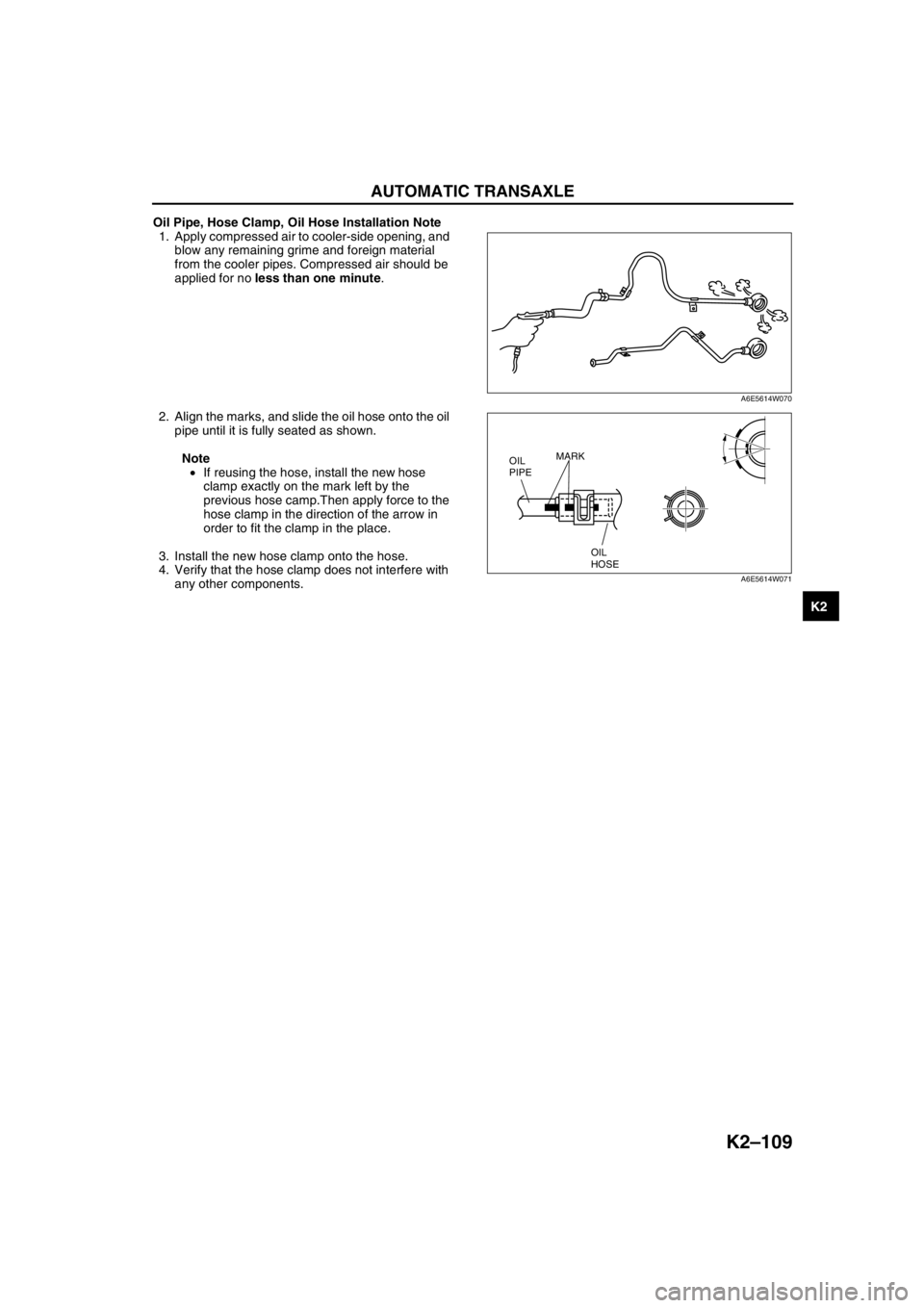
1. Apply compressed air to cooler-side opening, and
blow any remaining grime and foreign material
from the cooler pipes. Compressed air should be
applied for no less than one minute.
2. Align the marks, and slide the oil hose onto the oil
pipe until it is fully seated as shown.
Note
•If reusing the hose, install the new hose
clamp exactly on the mark left by the
previous hose camp.Then apply force to the
hose clamp in the direction of the arrow in
order to fit the clamp in the place.
3. Install the new hose clamp onto the hose.
4. Verify that the hose clamp does not interfere with
any other components.
End Of Sie
A6E5614W070
OIL
HOSE OIL
PIPEMARK
A6E5614W071
Page 525 of 909
K2–110
AUTOMATIC TRANSAXLE
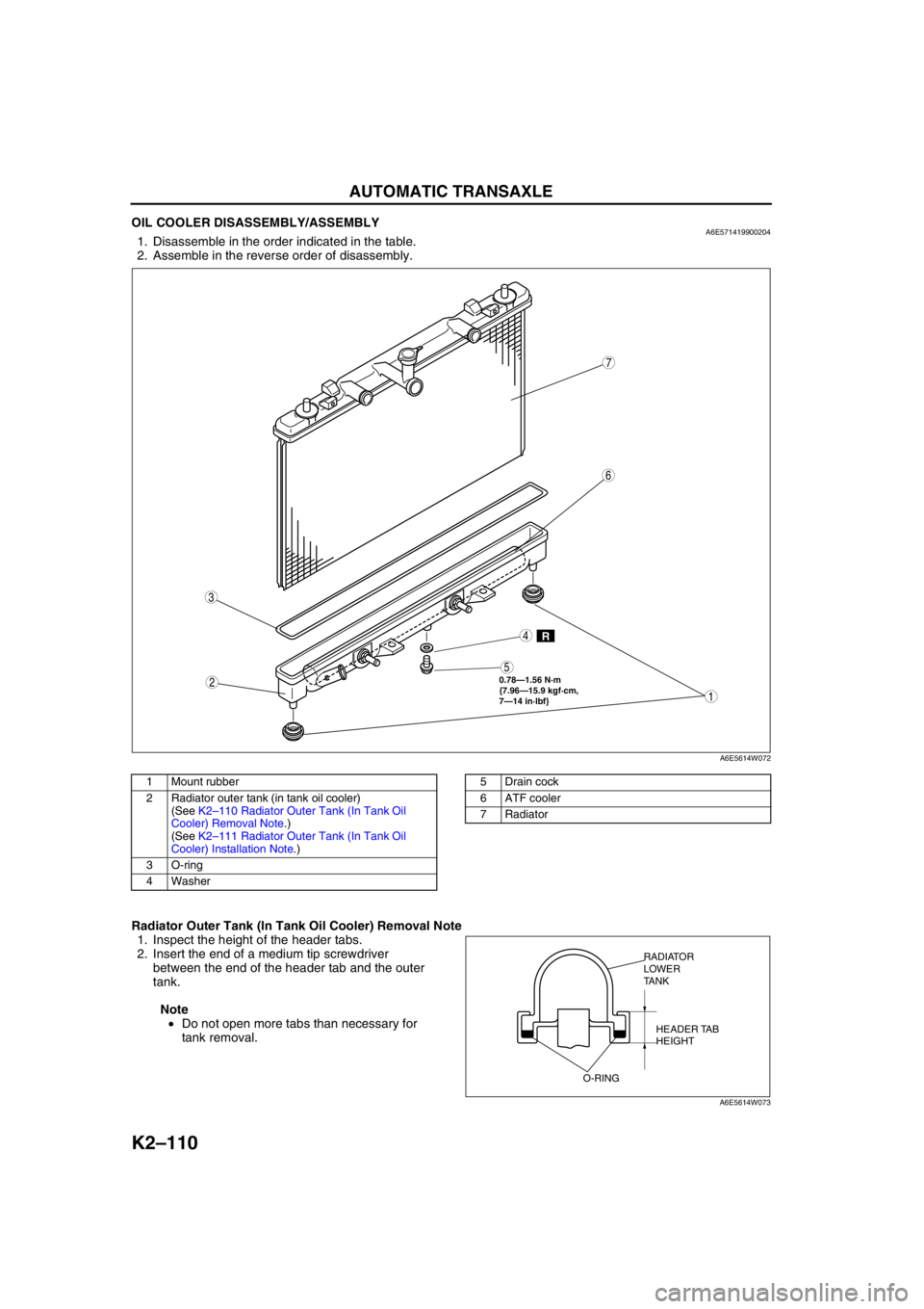
OIL COOLER DISASSEMBLY/ASSEMBLYA6E5714199002041. Disassemble in the order indicated in the table.
2. Assemble in the reverse order of disassembly.
.
Radiator Outer Tank (In Tank Oil Cooler) Removal Note
1. Inspect the height of the header tabs.
2. Insert the end of a medium tip screwdriver
between the end of the header tab and the outer
tank.
Note
•Do not open more tabs than necessary for
tank removal.
R
0.78—1.56 N·m
{7.96—15.9 kgf·cm,
7—14 in·lbf}
7
4
3
6
2
5
1
A6E5614W072
1 Mount rubber
2 Radiator outer tank (in tank oil cooler)
(See K2–110 Radiator Outer Tank (In Tank Oil
Cooler) Removal Note.)
(See K2–111 Radiator Outer Tank (In Tank Oil
Cooler) Installation Note.)
3 O-ring
4 Washer5 Drain cock
6 ATF cooler
7Radiator
RADIATOR
LOWER
TANK
HEADER TAB
HEIGHT
O-RING
A6E5614W073
Page 526 of 909
AUTOMATIC TRANSAXLE
K2–111
K2
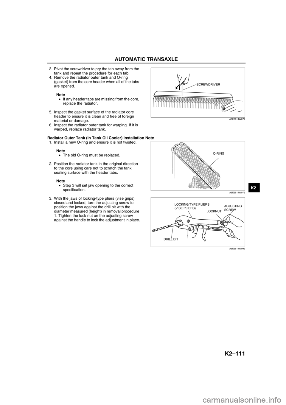
3. Pivot the screwdriver to pry the tab away from the
tank and repeat the procedure for each tab.
4. Remove the radiator outer tank and O-ring
(gasket) from the core header when all of the tabs
are opened.
Note
•If any header tabs are missing from the core,
replace the radiator.
5. Inspect the gasket surface of the radiator core
header to ensure it is clean and free of foreign
material or damage.
6. Inspect the radiator outer tank for warping. If it is
warped, replace radiator tank.
Radiator Outer Tank (In Tank Oil Cooler) Installation Note
1. Install a new O-ring and ensure it is not twisted.
Note
•The old O-ring must be replaced.
2. Position the radiator tank in the original direction
to the core using care not to scratch the tank
sealing surface with the header tabs.
Note
•Step 3 will set jaw opening to the correct
specification.
3. With the jaws of locking-type pliers (vise grips)
closed and locked, turn the adjusting screw to
position the jaws against the drill bit with the
diameter measured (height) in removal procedure
1. Tighten the lock nut on the adjusting screw
against the handle to lock the adjustment in place.
SCREWDRIVER
A6E5614W074
O-RING
A6E5614W075
LOCKING TYPE PLIERS
(VISE PLIERS)
LOCKNUTADJUSTING
SCREW
DRILL BIT
A6E5614W093
Page 527 of 909
K2–112
AUTOMATIC TRANSAXLE
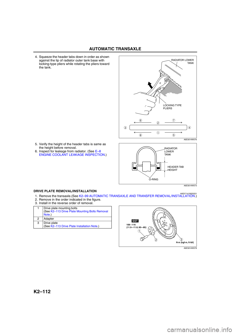
4. Squeeze the header tabs down in order as shown
against the lip of radiator outer tank base with
locking-type pliers while rotating the pliers toward
the tank.
5. Verify the height of the header tabs is same as
the height before removal.
6. Inspect for leakage from radiator. (See E–8
ENGINE COOLANT LEAKAGE INSPECTION.)
End Of SieDRIVE PLATE REMOVAL/INSTALLATIONA6E5714190202011. Remove the transaxle.(See K2–99 AUTOMATIC TRANSAXLE AND TRANSFER REMOVAL/INSTALLATION.)
2. Remove in the order indicated in the figure.
3. Install in the reverse order of removal.
.
8
7
5
43
6
1
2
LOCKING TYPE
PLIERSRADIATOR LOWER
TANK
A6E5614W076
RADIATOR
LOWER
TANK
HEADER TAB
HEIGHT
O-RING
A6E5614W073
1 Drive plate mounting bolts
(See K2–113 Drive Plate Mounting Bolts Removal
Note.)
2 Adapter
3 Drive plate
(See K2–113 Drive Plate Installation Note.)
N·m {kgf·m, ft·lbf} 108—116
{11.0—11.8, 80—85}
SST
3
1
2
A6E5614W078
Page 528 of 909
AUTOMATIC TRANSAXLE
K2–113
K2
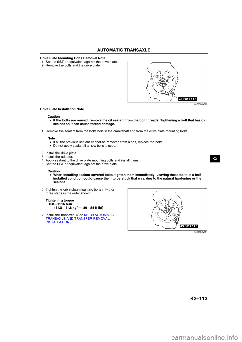
Drive Plate Mounting Bolts Removal Note
1. Set the SST or equivalent against the drive plate.
2. Remove the bolts and the drive plate.
Drive Plate Installation Note
Caution
•If the bolts are reused, remove the oil sealant from the bolt threads. Tightening a bolt that has old
sealant on it can cause thread damage.
1. Remove the sealant from the bolts hole in the crankshaft and from the drive plate mounting bolts.
Note
•If all the previous sealant cannot be removed from a bolt, replace the bolts.
•Do not apply sealant if a new bolts is used.
2. Install the drive plate.
3. Install the adapter.
4. Apply sealant to the drive plate mounting bolts and install them.
5. Set the SST or equivalent against the drive plate.
Caution
•When installing sealant covered bolts, tighten them immediately. Leaving these bolts in a half
installed condition could cause them to be stuck that way, due to the natural hardening or the
sealant.
6. Tighten the drive plate mounting bolts in two or
three steps in the order shown.
Tightening torque
108—1116 N·m
{11.0—11.8 kgf·m, 80—85 ft·lbf}
7. Install the transaxle. (See K2–99 AUTOMATIC
TRANSAXLE AND TRANSFER REMOVAL/
INSTALLATION.)
End Of Sie
5
4
361
2
49 E011 1A0
A6E5614W079
49 E011 1A0
5
4
361
2
A6E5614W081
Page 529 of 909
K2–114
TRANSFER
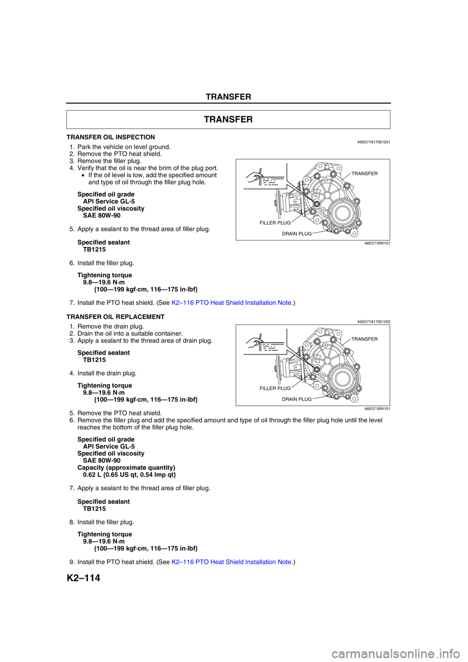
TRANSFER OIL INSPECTIONA6E5718170012011. Park the vehicle on level ground.
2. Remove the PTO heat shield.
3. Remove the filler plug.
4. Verify that the oil is near the brim of the plug port.
•If the oil level is low, add the specified amount
and type of oil through the filler plug hole.
Specified oil grade
API Service GL-5
Specified oil viscosity
SAE 80W-90
5. Apply a sealant to the thread area of filler plug.
Specified sealant
TB1215
6. Install the filler plug.
Tightening torque
9.8—19.6 N·m
{100—199 kgf·cm, 116—175 in·lbf}
7. Install the PTO heat shield. (See K2–116 PTO Heat Shield Installation Note.)
End Of Sie
TRANSFER OIL REPLACEMENTA6E5718170012021. Remove the drain plug.
2. Drain the oil into a suitable container.
3. Apply a sealant to the thread area of drain plug.
Specified sealant
TB1215
4. Install the drain plug.
Tightening torque
9.8—19.6 N·m
{100—199 kgf·cm, 116—175 in·lbf}
5. Remove the PTO heat shield.
6. Remove the filler plug and add the specified amount and type of oil through the filler plug hole until the level
reaches the bottom of the filler plug hole.
Specified oil grade
API Service GL-5
Specified oil viscosity
SAE 80W-90
Capacity (approximate quantity)
0.62 L {0.65 US qt, 0.54 lmp qt}
7. Apply a sealant to the thread area of filler plug.
Specified sealant
TB1215
8. Install the filler plug.
Tightening torque
9.8—19.6 N·m
{100—199 kgf·cm, 116—175 in·lbf}
9. Install the PTO heat shield. (See K2–116 PTO Heat Shield Installation Note.)
TRANSFER
TRANSFER
FILLER PLUG
DRAIN PLUG
A6E5718W101
TRANSFER
FILLER PLUG
DRAIN PLUG
A6E5718W101
Page 530 of 909
TRANSFER
K2–115
K2
End Of SieTRANSFER REMOVAL/INSTALLATIONA6E5718170012041. Disconnect the negative battery cable.
2. Remove the propeller shaft. (See L–5 PROPELLER SHAFT REMOVAL/INSTALLATION.)
3. Remove the TWC. (See F1–30 EXHAUST SYSTEM REMOVAL/INSTALLATION.)
4. Remove the front tires and splash shield of right side.
5. Remove the under cover.
6. Remove the drive shaft of right side. (See Section M.)
7. Remove the joint shaft. (See Section M.)
8. Remove the exhaust manifold insulator. (See F1–30 EXHAUST SYSTEM REMOVAL/INSTALLATION.)
9. Remove the exhaust manifold. (See F1–30 EXHAUST SYSTEM REMOVAL/INSTALLATION.)
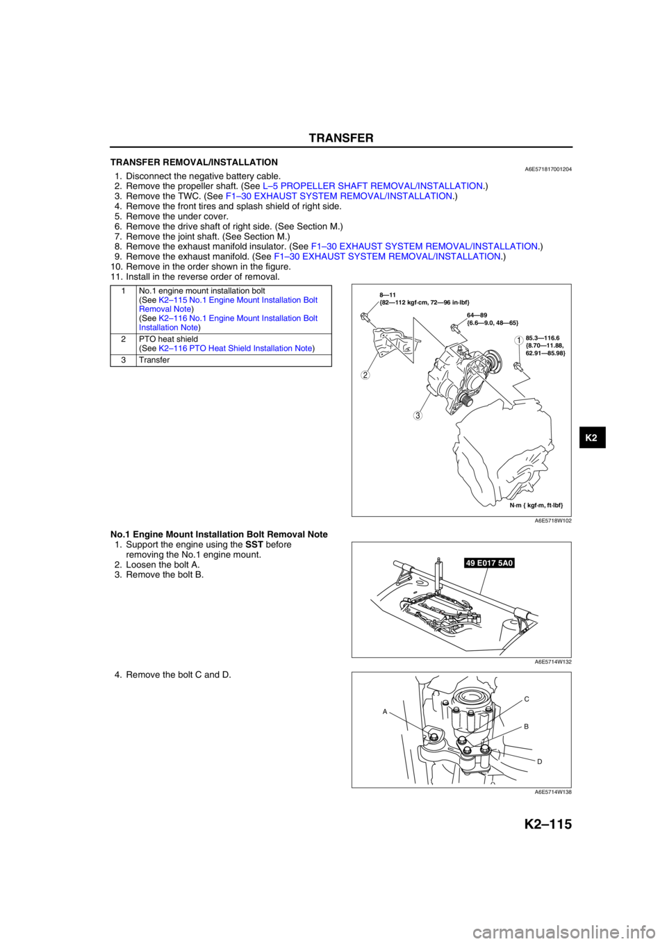
10. Remove in the order shown in the figure.
11. Install in the reverse order of removal.
.
No.1 Engine Mount Installation Bolt Removal Note
1. Support the engine using the SST before
removing the No.1 engine mount.
2. Loosen the bolt A.
3. Remove the bolt B.
4. Remove the bolt C and D.
1 No.1 engine mount installation bolt
(See K2–115 No.1 Engine Mount Installation Bolt
Removal Note)
(See K2–116 No.1 Engine Mount Installation Bolt
Installation Note)
2 PTO heat shield
(See K2–116 PTO Heat Shield Installation Note)
3Transfer
2
3
N·m { kgf·m, ft·lbf} 8—11
{82—112 kgf·cm, 72—96 in·lbf}
64—89
{6.6—9.0, 48—65}
185.3—116.6
{8.70—11.88,
62.91—85.98}
A6E5718W102
49 E017 5A0
A6E5714W132
AC
B
D
A6E5714W138