MAZDA 6 2002 Workshop Manual Suplement
Manufacturer: MAZDA, Model Year: 2002, Model line: 6, Model: MAZDA 6 2002Pages: 909, PDF Size: 17.16 MB
Page 531 of 909
K2–116
TRANSFER
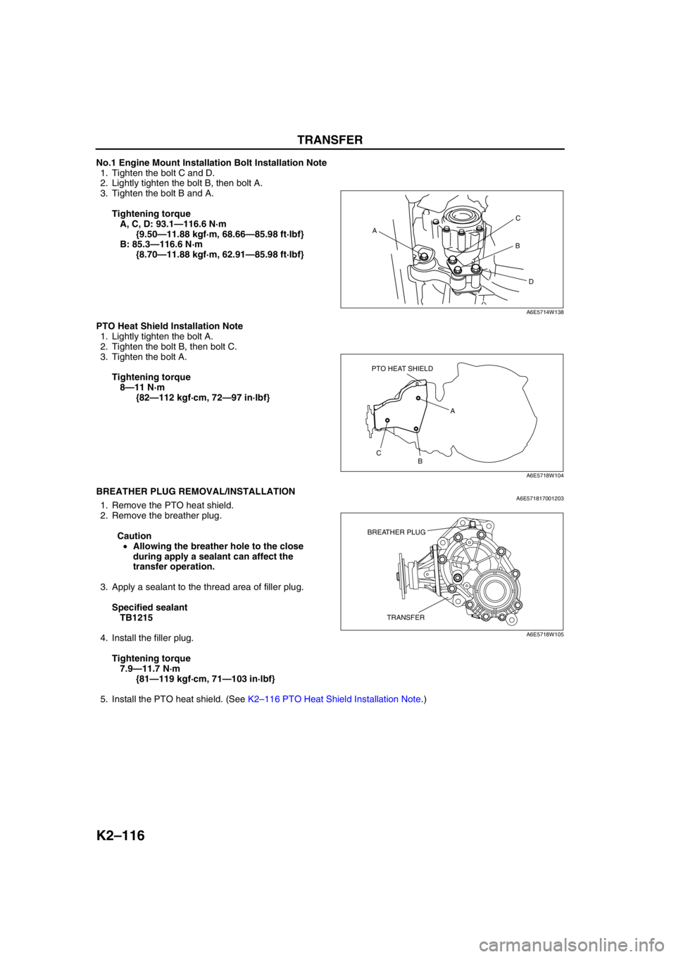
No.1 Engine Mount Installation Bolt Installation Note
1. Tighten the bolt C and D.
2. Lightly tighten the bolt B, then bolt A.
3. Tighten the bolt B and A.
Tightening torque
A, C, D: 93.1—116.6 N·m
{9.50—11.88 kgf·m, 68.66—85.98 ft·lbf}
B: 85.3—116.6 N·m
{8.70—11.88 kgf·m, 62.91—85.98 ft·lbf}
PTO Heat Shield Installation Note
1. Lightly tighten the bolt A.
2. Tighten the bolt B, then bolt C.
3. Tighten the bolt A.
Tightening torque
8—11 N·m
{82—112 kgf·cm, 72—97 in·lbf}
End Of SieBREATHER PLUG REMOVAL/INSTALLATIONA6E5718170012031. Remove the PTO heat shield.
2. Remove the breather plug.
Caution
•Allowing the breather hole to the close
during apply a sealant can affect the
transfer operation.
3. Apply a sealant to the thread area of filler plug.
Specified sealant
TB1215
4. Install the filler plug.
Tightening torque
7.9—11.7 N·m
{81—119 kgf·cm, 71—103 in·lbf}
5. Install the PTO heat shield. (See K2–116 PTO Heat Shield Installation Note.)
End Of Sie
AC
B
D
A6E5714W138
PTO HEAT SHIELD
A
B C
A6E5718W104
TRANSFER BREATHER PLUG
A6E5718W105
Page 532 of 909
AUTOMATIC TRANSAXLE SHIFT MECHANISM
K2–117
K2
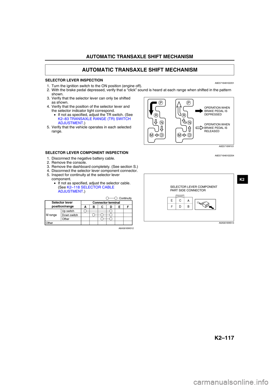
SELECTOR LEVER INSPECTIONA6E5716461022011. Turn the ignition switch to the ON position (engine off).
2. With the brake pedal depressed, verify that a “click” sound is heard at each range when shifted in the pattern
shown.
3. Verify that the selector lever can only be shifted
as shown.
4. Verify that the position of the selector lever and
the selector indicator light correspond.
•If not as specified, adjust the TR switch. (See
K2–83 TRANSAXLE RANGE (TR) SWITCH
ADJUSTMENT.)
5. Verify that the vehicle operates in each selected
range.
End Of SieSELECTOR LEVER COMPONENT INSPECTIONA6E5716461022041. Disconnect the negative battery cable.
2. Remove the console.
3. Remove the dashboard completely. (See section S.)
4. Disconnect the selector lever component connector.
5. Inspect for continuity at the selector lever
component.
•If not as specified, adjust the selector cable.
(See K2–118 SELECTOR CABLE
ADJUSTMENT.)
End Of Sie
AUTOMATIC TRANSAXLE SHIFT MECHANISM
P
R
N
DM
P
R
N
DM
OPERATION WHEN
BRAKE PEDAL IS
DEPRESSED
OPERATION WHEN
BRAKE PEDAL IS
RELEASED
A6E5716W101
SELECTOR LEVER COMPONENT
PART SIDE CONNECTOR
A6A5616W013
A6A5616W012
Page 533 of 909

K2–118
AUTOMATIC TRANSAXLE SHIFT MECHANISM
SELECTOR CABLE ADJUSTMENTA6E5716465002011. Remove the center console.
2. Shift the selector lever to P position.
3. Unlock the lock piece of the selector cable
(selector lever side) in the order shown in the
figure.
4. Verify that the manual shaft is in P position.
5. Lock the lock piece of the selector cable (selector
lever side) in the order shown in the figure.
6. Install the center console.
7. Shift the selector lever from P position to M range,
and make sure that there are no other
components in that area to interfere with the lever.
End Of Sie
1
2
SAFETY
LOCK
LOCK PIECE
A6E5716W102
2
1
SAFETY
LOCK
LOCK PIECE
A6E5716W103
Page 534 of 909

AUTOMATIC TRANSAXLE SHIFT MECHANISM
K2–119
K2
SELECTOR LEVER REMOVAL/INSTALLATIONA6E5716461022021. Disconnect the negative battery cable.
2. Remove the battery and battery tray.
3. Remove the air cleaner compornent. (See Section F.)
4. Remove the console.
5. Remove the dashboard compleat. (See Section S.)
6. Remove the SAS control module. (See Section T.)
7. Remove the climate control unit. (See Section U.)
8. Remove the rear heat duct. (See Section U.)
9. Remove in the order shown in the figure.
10. Install in the reverse order of removal.
.
1
2
A
A
B
15.68—22.5
{1.60—2.29, 11.6—16.5}
B6.86—9.8 N·m
{70—99 kgf·cm, 61—86 in·lbf}
N·m {kgf·m, ft·lbf}
A6E5716W104
1 Selector cable
(See K2–120 Selector Cable Removal Note.)
(See K2–120 Selector Cable Installation Note.)2Selector lever
Page 535 of 909

K2–120
AUTOMATIC TRANSAXLE SHIFT MECHANISM
Selector Cable Removal Note
1. Remove the spring.
2. Remove the selector cable.
Selector Cable Installation Note
1. Install the selector cable to the selector lever certainly.
2. Install the selector cable to the bracket certainly.
Note
•Step 3, 4 is for the selector cable
replacement only.
3. Verify that the selector lever is in P position.
4. Lock the lock piece of the selector cable (selector
lever side) in the order shown in the figure.
5. Verify that the manual shaft is in P position.
SPRING SELECTOR CABLE
A6E5716W105
SELECTOR CABLE
A6E5616W020
2
1
SAFETY
LOCK
LOCK PIECE
A6E5716W103
DO NOT BEND
A6E5616W007
Page 536 of 909
AUTOMATIC TRANSAXLE SHIFT MECHANISM
K2–121
K2
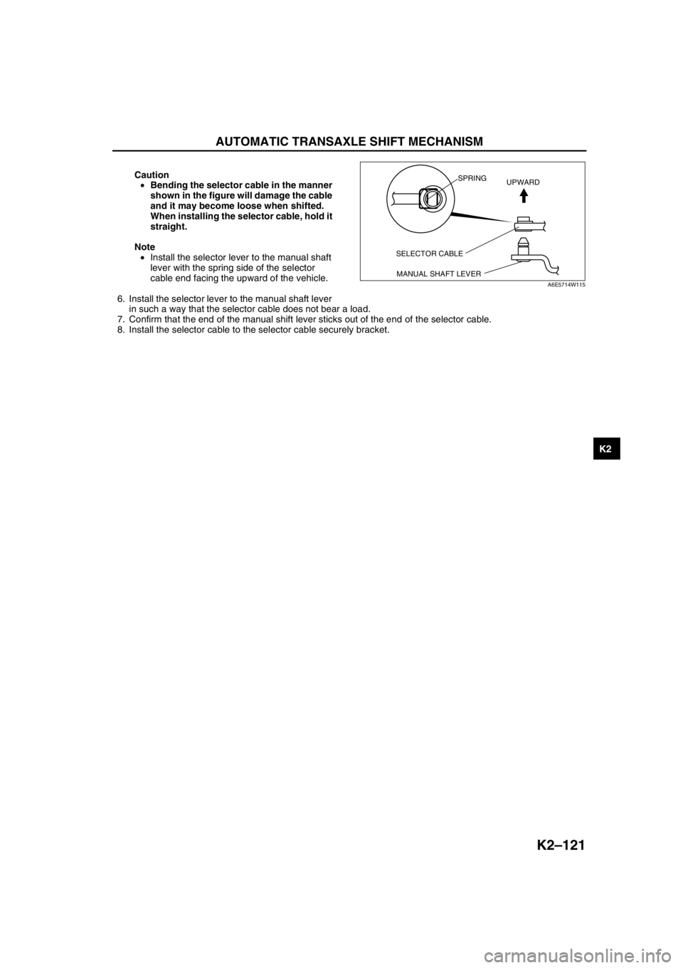
Caution
•Bending the selector cable in the manner
shown in the figure will damage the cable
and it may become loose when shifted.
When installing the selector cable, hold it
straight.
Note
•Install the selector lever to the manual shaft
lever with the spring side of the selector
cable end facing the upward of the vehicle.
6. Install the selector lever to the manual shaft lever
in such a way that the selector cable does not bear a load.
7. Confirm that the end of the manual shift lever sticks out of the end of the selector cable.
8. Install the selector cable to the selector cable securely bracket.
End Of Sie
SELECTOR CABLE
MANUAL SHAFT LEVERSPRING
UPWARD
A6E5714W115
Page 537 of 909
K2–122
AUTOMATIC TRANSAXLE SHIFT MECHANISM
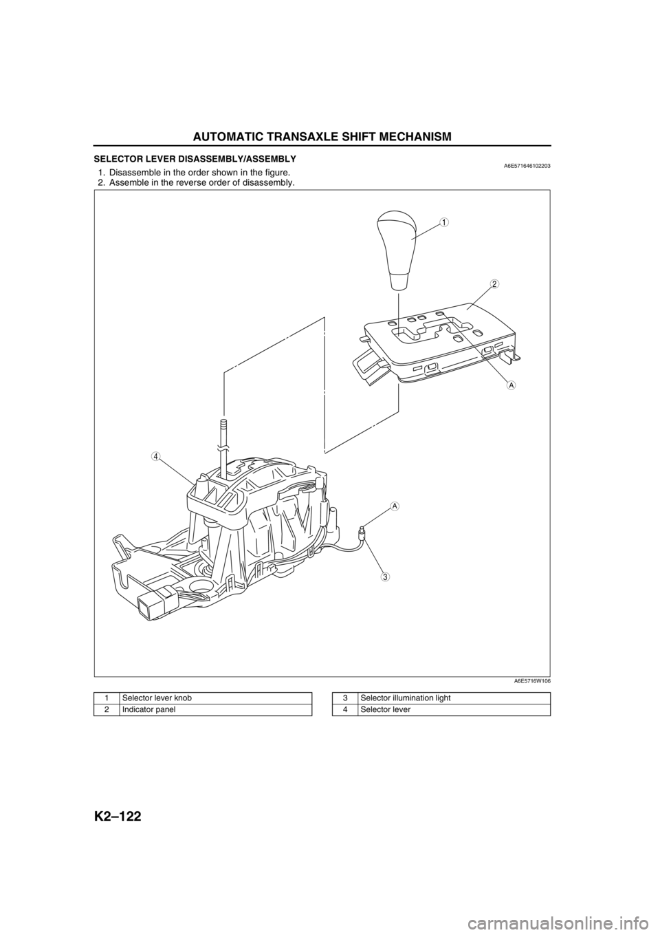
SELECTOR LEVER DISASSEMBLY/ASSEMBLYA6E5716461022031. Disassemble in the order shown in the figure.
2. Assemble in the reverse order of disassembly.
.
End Of Sie
3
A
A
2
1
4
A6E5716W106
1 Selector lever knob
2 Indicator panel3 Selector illumination light
4 Selector lever
Page 538 of 909
ON-BOARD DIAGNOSTIC
K2–123
K2
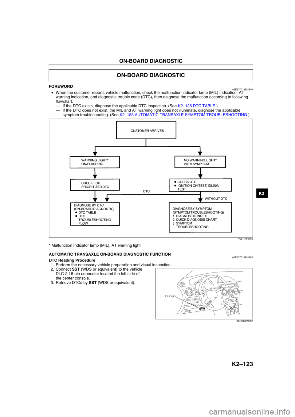
FOREWORDA6E577018901201•When the customer reports vehicle malfunction, check the malfunction indicator lamp (MIL) indication, AT
warning indication, and diagnostic trouble code (DTC), then diagnose the malfunction according to following
flowchart.
—If the DTC exists, diagnose the applicable DTC inspection. (See K2–126 DTC TABLE.)
—If the DTC does not exist, the MIL and AT warning light does not illuminate, diagnose the applicable
symptom troubleshooting. (See K2–183 AUTOMATIC TRANSAXLE SYMPTOM TROUBLESHOOTING.)
*:Malfunction Indicator lamp (MIL), AT warning light
End Of Sie
AUTOMATIC TRANSAXLE ON-BOARD DIAGNOSTIC FUNCTIONA6E577018901202DTC Reading Procedure
1. Perform the necessary vehicle preparation and visual inspection.
2. Connect SST (WDS or equivalent) to the vehicle
DLC-2 16-pin connector located the left side of
the center console.
3. Retrieve DTCs by SST (WDS or equivalent).
End Of Sie
ON-BOARD DIAGNOSTIC
YMU102WBX
DLC-2
A6E3970W002
Page 539 of 909

K2–124
ON-BOARD DIAGNOSTIC
AFTER REPAIR PROCEDUREA6E577018901203
Caution
•After repairing a malfunction, perform this procedure to verify that the malfunction has been
corrected.
•When this procedure is carried out, be sure to drive the vehicle at lawful speed and pay attention
to the other vehicles.
1. Connect the SST (WDS or equivalent) to the DLC-2.
2. Turn the ignition key to ON (engine OFF).
3. Select the clear code function and clear the DTC.
4. Perform the following trouble code inspections to ensure that the DTC has been resolved:
•For P0705
i. Start the engine.
ii. Warm up the engine to normal operating temperature.
iii. Depress the brake pedal, and shift the selector lever between P to D for 5 seconds or more.
iv. Go to Step 5.
•For P0706
i. Start the engine.
ii. Warm up the engine to normal operating temperature.
iii. Depress the brake pedal, and shift the selector lever between P to D for 100 seconds or more.
iv. Go to Step 5.
•For P0711
i. Decrease ATF temperature to 20 °C {68 °F} or below.
ii. Start the engine.
iii. Drive the vehicle in D range for 10 minutes or more.
iv. Go to Step 5
•For P0712
i. Start the engine.
ii. Warm up the engine to normal operating temperature.
iii. Drive the vehicle in D range for 20 seconds or more.
iv. Go to Step 5.
•For P0713
i. Start the engine.
ii. Warm up the engine to normal operating temperature.
iii. Drive the vehicle in D range at 20 km/h {12mph} or above for 300 seconds or more.
iv. Go to Step 5.
•For P0715; P0791
i. Start the engine.
ii. Drive the vehicle under the following conditions for 2 seconds or more.
—Vehicle speed (VSS PID): 40 km/h {25 mph} or above
—Engine speed (RPM PID): 1,500 rpm or above.
—Selector lever position: D range
iii. Repeat Step ii again.
iv. Turn the IG switch to OFF.
v. Start the engine.
vi. Drive vehicle under the following conditions for 2 second or more.
—Vehicle speed (VSS PID): 40 km/h {25 mph} or above
—Engine speed (RPM PID): 1,500 rpm or above.
—Selector lever position: D range
vii. Go to Step 5.
•For P0720
i. Start the engine.
ii. Warm up the engine and ATX.
iii. Drive vehicle under the following conditions for 2 seconds or more.
—Selector lever position: D range
—Vehicle speed (VSS PID): 40 km/h {25 mph}
—Engine speed (RPM PID): 1,500 rpm or above.
iv. Go to Step 5.
Page 540 of 909

ON-BOARD DIAGNOSTIC
K2–125
K2
•For P0740
i. Start the engine.
ii. Warm up the engine and ATX.
iii. Drive vehicle under the following conditions for 10 seconds or more.
—Vehicle speed (VSS PID): 76 km/h {47 mph}
—Selector lever position: D range
—TCC operating
iv. Go to Step 5.
•For P0743
i. Start the engine.
ii. Warm up the engine and ATX.
iii. Drive the vehicle in D range and make sure that the gears shift smoothly from 1GR to 5GR and TCC is
operated.
iv. Go to Step 5.
•For P0748, P0751, P0752, P0753, P0756, P0757, P0758, P0761, P0762, P0763, P0768, P0773, P0778,
P0798, P1710, PC073, PC100
i. Start the engine.
ii. Warm up the engine and ATX.
iii. Drive the vehicle in D range and make sure that the gears shift smoothly from 1GR to 5GR.
iv. Go to Step 5.
5. Gradually slow down and stop the vehicle.
6. Make sure that the repaired DTC does not recur.
End Of Sie