MAZDA 6 2002 Workshop Manual Suplement
Manufacturer: MAZDA, Model Year: 2002, Model line: 6, Model: MAZDA 6 2002Pages: 909, PDF Size: 17.16 MB
Page 681 of 909

REAR DIFFERENTIAL
M–51
M
REAR DIFFERENTIAL REMOVAL/INSTALLATIONA6E6319271002071. Drain the rear differential oil into a container.
2. Remove the after silencer, presilencer, and catalytic converter. (See F1–30 EXHAUST SYSTEM REMOVAL/
INSTALLATION.)
3. Remove the propeller shaft. (See L–5 PROPELLER SHAFT REMOVAL/INSTALLATION.)
4. Remove the rear drive shaft. (See M–43 REAR DRIVE SHAFT REMOVAL/INSTALLATION.)
5. Remove in the order indicated in the table.
6. Install in the reverse order of removal.
7. Add the specified rear differential oil.
.
SEALANTSEALANT
5
3
12
6
86.2—116.6
{8.8—11.9,
63.6—85.9}
74.5—104.9
{7.6—10.6, 55.0—77.3}
43.1—60.8
{4.4—6.1,
31.8—44.8}
22.6—26.4
{2.4—2.6,
16.7—19.4}
4
N·m {kgf·m, ft·lbf}
A6E63192201
1 Differential oil temperature sensor connector
2 4WD solenoid connector
3 Coupling component and rear differential
component
(See M–52 Coupling Component and Rear
Differential Component Removal/installation Note)
4 Rear differential bracket 5 Coupling component
(See M–68 COUPLING COMPONENT REMOVAL/
INSTALLATION)
6 Rear differential
Page 682 of 909
M–52
REAR DIFFERENTIAL
Coupling Component and Rear Differential Component Removal/installation Note
Warning
•Make sure that the coupling component and rear differential component are securely supported
by the jack. If the coupling component and rear differential component fall, it could cause death,
serious injury, or vehicle damage.
1. Make sure that the coupling component and rear
differential component are securely supported by
the jack, and remove/install the component by
operating the jack gradually.
End Of Sie
REAR DIFFERENTIAL DISASSEMBLYA6E631927100208
Warning
•The engine stand is equipped with a self-lock mechanism, however, if the rear differential is in a
tilted condition, the self-lock mechanism could become inoperative. If the rear differential
unexpectedly rotates it could cause injury, therefore do not maintain the rear differential in a tilted
condition. When turning the rear differential, grasp the rotation handle firmly.
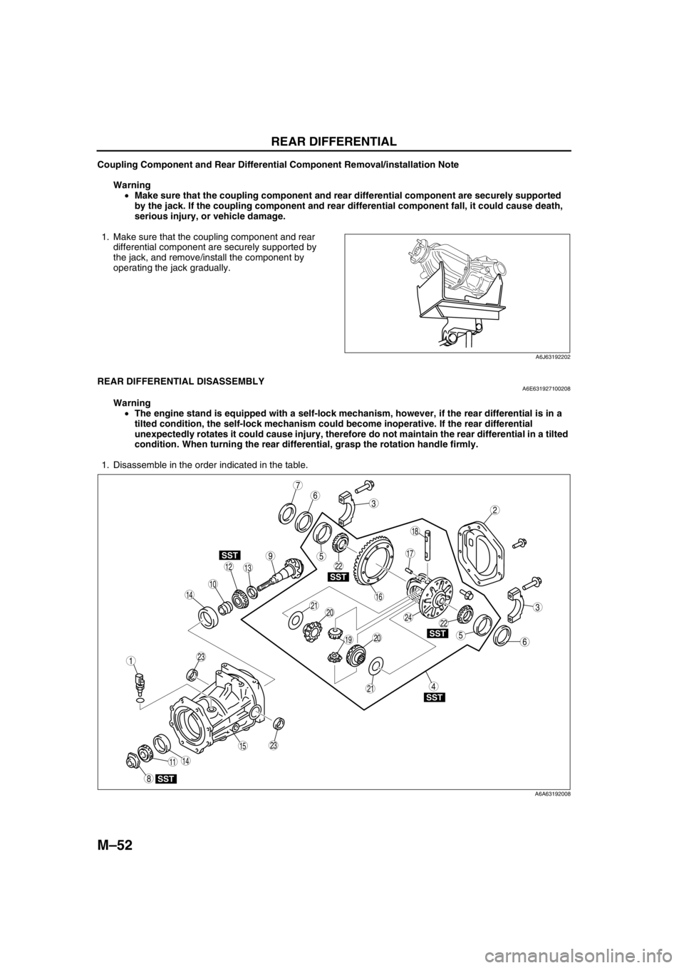
1. Disassemble in the order indicated in the table.
.
A6J63192202
9
7
3
10
SST
SST
SST
SST
SST
6
18
14
14
1312
8
5
5
4
3
1
2
19
17
15
16
11
20
2024
23
23
21
21
22
22
6
A6A63192008
Page 683 of 909
REAR DIFFERENTIAL
M–53
M
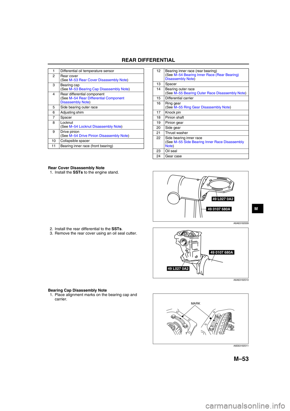
Rear Cover Disassembly Note
1. Install the SSTs to the engine stand.
2. Install the rear differential to the SSTs.
3. Remove the rear cover using an oil seal cutter.
Bearing Cap Disassembly Note
1. Place alignment marks on the bearing cap and
carrier.
1 Differential oil temperature sensor
2 Rear cover
(See M–53 Rear Cover Disassembly Note)
3 Bearing cap
(See M–53 Bearing Cap Disassembly Note)
4 Rear differential component
(See M–54 Rear Differential Component
Disassembly Note)
5 Side bearing outer race
6 Adjusting shim
7Spacer
8 Locknut
(See M–54 Locknut Disassembly Note)
9 Drive pinion
(See M–54 Drive Pinion Disassembly Note)
10 Collapsible spacer
11 Bearing inner race (front bearing)12 Bearing inner race (rear bearing)
(See M–54 Bearing Inner Race (Rear Bearing)
Disassembly Note)
13 Spacer
14 Bearing outer race
(See M–55 Bearing Outer Race Disassembly Note)
15 Differential carrier
16 Ring gear
(See M–55 Ring Gear Disassembly Note)
17 Knock pin
18 Pinion shaft
19 Pinion gear
20 Side gear
21 Thrust washer
22 Side bearing inner race
(See M–55 Side Bearing Inner Race Disassembly
Note)
23 Oil seal
24 Gear case
49 L027 0A2
49 0107 680A
A6A63192009
49 L027 0A2
49 0107 680A
A6A63192010
MARK
A6E63192011
Page 684 of 909
M–54
REAR DIFFERENTIAL
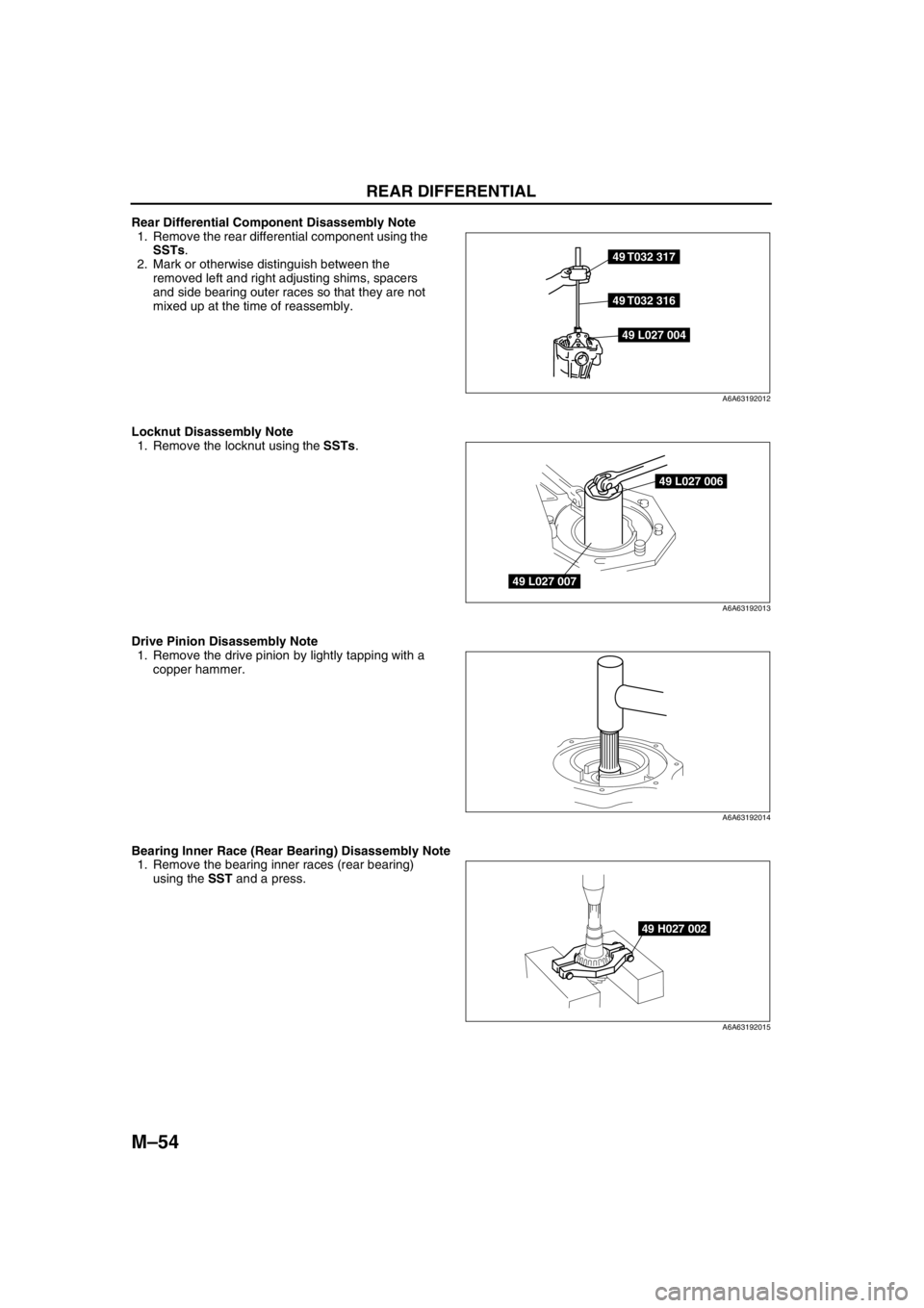
Rear Differential Component Disassembly Note
1. Remove the rear differential component using the
SSTs.
2. Mark or otherwise distinguish between the
removed left and right adjusting shims, spacers
and side bearing outer races so that they are not
mixed up at the time of reassembly.
Locknut Disassembly Note
1. Remove the locknut using the SSTs.
Drive Pinion Disassembly Note
1. Remove the drive pinion by lightly tapping with a
copper hammer.
Bearing Inner Race (Rear Bearing) Disassembly Note
1. Remove the bearing inner races (rear bearing)
using the SST and a press.
49 T032 317
49 T032 316
49 L027 004
A6A63192012
49 L027 006
49 L027 007
A6A63192013
A6A63192014
49 H027 002
A6A63192015
Page 685 of 909
REAR DIFFERENTIAL
M–55
M
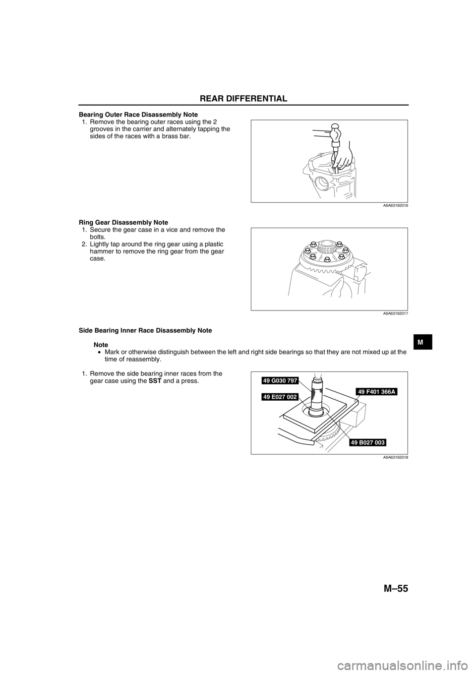
Bearing Outer Race Disassembly Note
1. Remove the bearing outer races using the 2
grooves in the carrier and alternately tapping the
sides of the races with a brass bar.
Ring Gear Disassembly Note
1. Secure the gear case in a vice and remove the
bolts.
2. Lightly tap around the ring gear using a plastic
hammer to remove the ring gear from the gear
case.
Side Bearing Inner Race Disassembly Note
Note
•Mark or otherwise distinguish between the left and right side bearings so that they are not mixed up at the
time of reassembly.
1. Remove the side bearing inner races from the
gear case using the SST and a press.
End Of Sie
A6A63192016
A6A63192017
49 B027 003
49 F401 366A
49 G030 797
49 E027 002
A6A63192018
Page 686 of 909
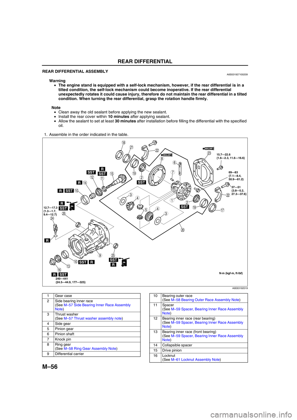
M–56
REAR DIFFERENTIAL
REAR DIFFERENTIAL ASSEMBLYA6E631927100209
Warning
•The engine stand is equipped with a self-lock mechanism, however, if the rear differential is in a
tilted condition, the self-lock mechanism could become inoperative. If the rear differential
unexpectedly rotates it could cause injury, therefore do not maintain the rear differential in a tilted
condition. When turning the rear differential, grasp the rotation handle firmly.
Note
•Clean away the old sealant before applying the new sealant.
•Install the rear cover within 10 minutes after applying sealant.
•Allow the sealant to set at least 30 minutes after installation before filling the differential with the specified
oil.
1. Assemble in the order indicated in the table.
.
SST
SST
SST
SSTSST
SST
SST
9
8
7
54
4
3
3
12
2
10
10
19
19
18
17
15
16
14
13
1112
20
25
25
24
23
21
22
22
R
SST
R
R
R
SSTR
RR
6
SEALANTSEALANT
SEALANTSEALANT
OILOIL
OILOIL
15.7—22.6
{1.6—2.3, 11.6—16.6}
37—51
{3.8—5.2,
27.3—37.6}
240—441
{24.5—44.9, 177—325} 12.7—17.3
{1.3—1.7,
9.4—12.7}69—83
{7.1—8.4,
50.9—61.2}
N·m {kgf·m, ft·lbf}
R
A6E63192019
1 Gear case
2 Side bearing inner race
(See M–57 Side Bearing Inner Race Assembly
Note)
3 Thrust washer
(See M–57 Thrust washer assembly note)
4 Side gear
5 Pinion gear
6Pinion shaft
7 Knock pin
8 Ring gear
(See M–58 Ring Gear Assembly Note)
9 Differential carrier10 Bearing outer race
(See M–58 Bearing Outer Race Assembly Note)
11 Spacer
(See M–59 Spacer, Bearing Inner Race Assembly
Note)
12 Bearing inner race (rear bearing)
(See M–59 Spacer, Bearing Inner Race Assembly
Note)
13 Bearing inner race (front bearing)
(See M–59 Spacer, Bearing Inner Race Assembly
Note)
14 Collapsible spacer
15 Drive pinion
16 Locknut
(See M–61 Locknut Assembly Note)
Page 687 of 909
REAR DIFFERENTIAL
M–57
M
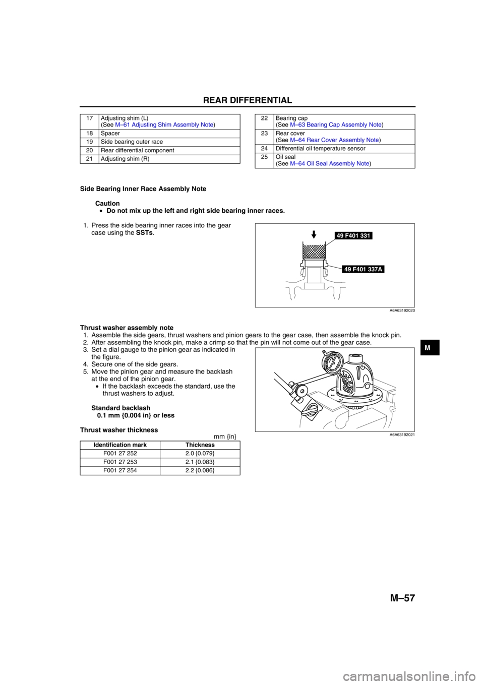
Side Bearing Inner Race Assembly Note
Caution
•Do not mix up the left and right side bearing inner races.
1. Press the side bearing inner races into the gear
case using the SSTs.
Thrust washer assembly note
1. Assemble the side gears, thrust washers and pinion gears to the gear case, then assemble the knock pin.
2. After assembling the knock pin, make a crimp so that the pin will not come out of the gear case.
3. Set a dial gauge to the pinion gear as indicated in
the figure.
4. Secure one of the side gears.
5. Move the pinion gear and measure the backlash
at the end of the pinion gear.
•If the backlash exceeds the standard, use the
thrust washers to adjust.
Standard backlash
0.1 mm {0.004 in} or less
Thrust washer thickness
mm {in}
17 Adjusting shim (L)
(See M–61 Adjusting Shim Assembly Note)
18 Spacer
19 Side bearing outer race
20 Rear differential component
21 Adjusting shim (R)22 Bearing cap
(See M–63 Bearing Cap Assembly Note)
23 Rear cover
(See M–64 Rear Cover Assembly Note)
24 Differential oil temperature sensor
25 Oil seal
(See M–64 Oil Seal Assembly Note)
49 F401 331
49 F401 337A
A6A63192020
Identification mark Thickness
F001 27 252 2.0 {0.079}
F001 27 253 2.1 {0.083}
F001 27 254 2.2 {0.086}
A6A63192021
Page 688 of 909

M–58
REAR DIFFERENTIAL
Ring Gear Assembly Note
Caution
•The differential gear and ring gear could be damaged if the ring gear is installed with old thread-
locking compound remaining on the bolt threads. Before installing the ring gear, completely
remove the old thread-locking compound from the bolt threads.
1. Apply a small amount of thread-locking
compound to each of points A on the back of the
ring gear, and bolt thread areas B (around the
entire ring).
Application amount
Back of ring gear:
Approx. 0.32 ml {0.32 cc, 0.02 cu in}
Ring gear bolt thread points:
Approx. 0.32 ml {0.32 cc, 0.02 cu in}
(0.04 ml {0.04 cc, 0.002 cu in}
to each point)
2. Align the marks placed on the ring gear case at
the time of disassembly and tighten the bolts in
diagonal order.
Tightening torque
69—83 N·m {7.1—8.4 kgf·m, 50.9—61.2 ft·lbf}
Bearing Outer Race Assembly Note
1. Press in the bearing outer race using the SSTs
and a press.
A
B
A6A63192022
A6A63192023
49 M005 797
49 F027 007
49 F027 005
A6A63192024
Page 689 of 909
REAR DIFFERENTIAL
M–59
M
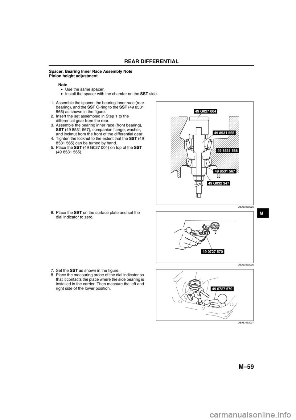
Spacer, Bearing Inner Race Assembly Note
Pinion height adjustment
Note
•Use the same spacer.
•Install the spacer with the chamfer on the SST side.
1. Assemble the spacer, the bearing inner race (rear
bearing), and the SST O-ring to the SST (49 8531
565) as shown in the figure.
2. Insert the set assembled in Step 1 to the
differential gear from the rear.
3. Assemble the bearing inner race (front bearing),
SST (49 8531 567), companion flange, washer,
and locknut from the front of the differential gear.
4. Tighten the locknut to the extent that the SST (49
8531 565) can be turned by hand.
5. Place the SST (49 G027 004) on top of the SST
(49 8531 565).
6. Place the SST on the surface plate and set the
dial indicator to zero.
7. Set the SST as shown in the figure.
8. Place the measuring probe of the dial indicator so
that it contacts the place where the side bearing is
installed in the carrier. Then measure the left and
right side of the lower position.
49 G027 004
49 8531 565
49 8531 568
49 8531 567
49 G032 347
A6A63192025
49 0727 570
A6A63192026
49 0727 570
A6A63192027
Page 690 of 909
M–60
REAR DIFFERENTIAL
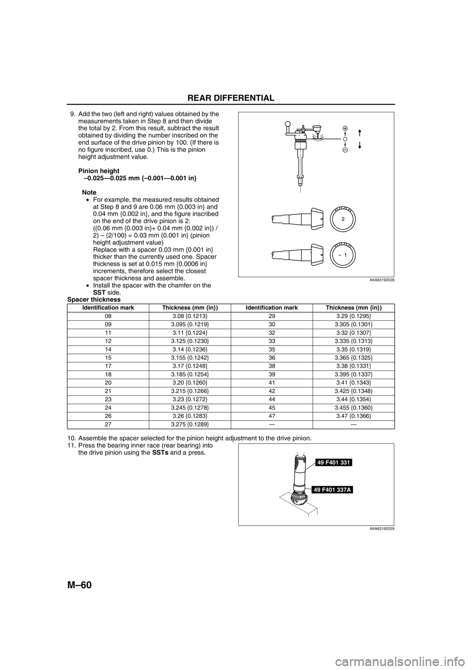
9. Add the two (left and right) values obtained by the
measurements taken in Step 8 and then divide
the total by 2. From this result, subtract the result
obtained by dividing the number inscribed on the
end surface of the drive pinion by 100. (If there is
no figure inscribed, use 0.) This is the pinion
height adjustment value.
Pinion height
–0.025—0.025 mm {–0.001—0.001 in}
Note
•For example, the measured results obtained
at Step 8 and 9 are 0.06 mm {0.003 in} and
0.04 mm {0.002 in}, and the figure inscribed
on the end of the drive pinion is 2:
((0.06 mm {0.003 in}+ 0.04 mm {0.002 in}) /
2) – (2/100) = 0.03 mm {0.001 in} (pinion
height adjustment value)
Replace with a spacer 0.03 mm {0.001 in}
thicker than the currently used one. Spacer
thickness is set at 0.015 mm {0.0006 in}
increments, therefore select the closest
spacer thickness and assemble.
•Install the spacer with the chamfer on the
SST side.
Spacer thickness
10. Assemble the spacer selected for the pinion height adjustment to the drive pinion.
11. Press the bearing inner race (rear bearing) into
the drive pinion using the SSTs and a press.
A6A63192028
Identification mark Thickness (mm {in}) Identification mark Thickness (mm {in})
08 3.08 {0.1213} 29 3.29 {0.1295}
09 3.095 {0.1219} 30 3.305 {0.1301}
11 3.11 {0.1224} 32 3.32 {0.1307}
12 3.125 {0.1230} 33 3.335 {0.1313}
14 3.14 {0.1236} 35 3.35 {0.1319}
15 3.155 {0.1242} 36 3.365 {0.1325}
17 3.17 {0.1248} 38 3.38 {0.1331}
18 3.185 {0.1254} 39 3.395 {0.1337}
20 3.20 {0.1260} 41 3.41 {0.1343}
21 3.215 {0.1266} 42 3.425 {0.1348}
23 3.23 {0.1272} 44 3.44 {0.1354}
24 3.245 {0.1278} 45 3.455 {0.1360}
26 3.26 {0.1283} 47 3.47 {0.1366}
27 3.275 {0.1289}——
49 F401 331
49 F401 337A
A6A63192029