MAZDA 6 2002 Workshop Manual Suplement
Manufacturer: MAZDA, Model Year: 2002, Model line: 6, Model: MAZDA 6 2002Pages: 909, PDF Size: 17.16 MB
Page 701 of 909
ELECTRONIC 4WD CONTROL SYSTEM
M–71
M
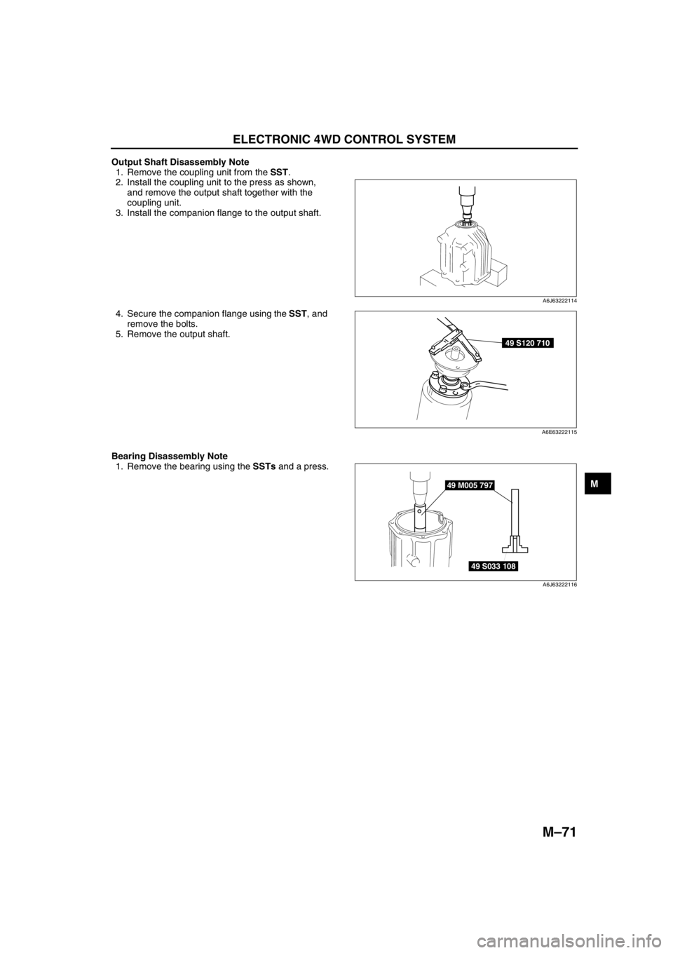
Output Shaft Disassembly Note
1. Remove the coupling unit from the SST.
2. Install the coupling unit to the press as shown,
and remove the output shaft together with the
coupling unit.
3. Install the companion flange to the output shaft.
4. Secure the companion flange using the SST, and
remove the bolts.
5. Remove the output shaft.
Bearing Disassembly Note
1. Remove the bearing using the SSTs and a press.
End Of Sie
A6J63222114
49 S120 710
A6E63222115
49 M005 797
49 S033 108
A6J63222116
Page 702 of 909
M–72
ELECTRONIC 4WD CONTROL SYSTEM
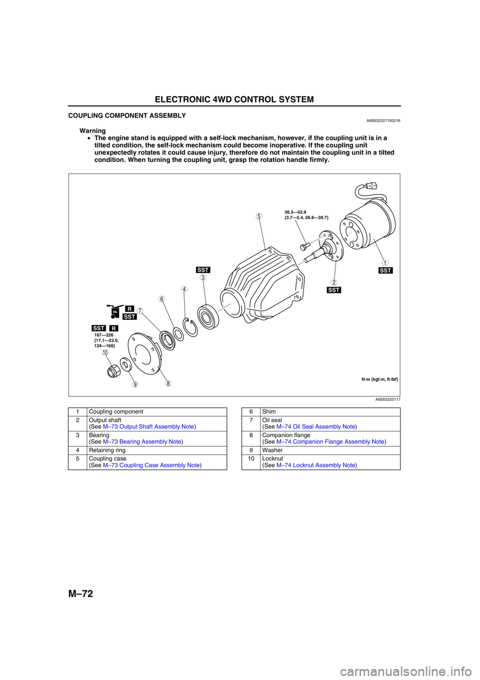
COUPLING COMPONENT ASSEMBLYA6E632227100216
Warning
•The engine stand is equipped with a self-lock mechanism, however, if the coupling unit is in a
tilted condition, the self-lock mechanism could become inoperative. If the coupling unit
unexpectedly rotates it could cause injury, therefore do not maintain the coupling unit in a tilted
condition. When turning the coupling unit, grasp the rotation handle firmly.
.
98
7
5
4
3
1
2
10
6
SST
SST
R
SST
SST
SST
R
OIL
36.3—53.9
{3.7—5.4, 26.8—39.7}
167—226
{17.1—23.0,
124—166}
N·m {kgf·m, ft·lbf}
A6E63222117
1 Coupling component
2 Output shaft
(See M–73 Output Shaft Assembly Note)
3 Bearing
(See M–73 Bearing Assembly Note)
4 Retaining ring
5 Coupling case
(See M–73 Coupling Case Assembly Note)6Shim
7 Oil seal
(See M–74 Oil Seal Assembly Note)
8 Companion flange
(See M–74 Companion Flange Assembly Note)
9Washer
10 Locknut
(See M–74 Locknut Assembly Note)
Page 703 of 909
ELECTRONIC 4WD CONTROL SYSTEM
M–73
M
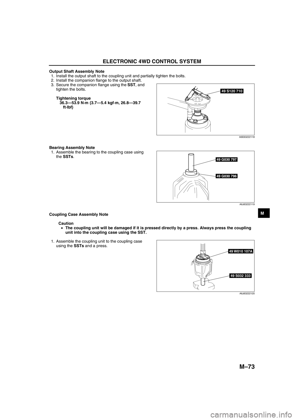
Output Shaft Assembly Note
1. Install the output shaft to the coupling unit and partially tighten the bolts.
2. Install the companion flange to the output shaft.
3. Secure the companion flange using the SST, and
tighten the bolts.
Tightening torque
36.3—53.9 N·m {3.7—5.4 kgf·m, 26.8—39.7
ft·lbf}
Bearing Assembly Note
1. Assemble the bearing to the coupling case using
the SSTs.
Coupling Case Assembly Note
Caution
•The coupling unit will be damaged if it is pressed directly by a press. Always press the coupling
unit into the coupling case using the SST.
1. Assemble the coupling unit to the coupling case
using the SSTs and a press.
49 S120 710
A6E63222118
49 G030 797
49 G030 796
A6J63222119
49 S032 333
49 W010 107A
A6J63222120
Page 704 of 909
M–74
ELECTRONIC 4WD CONTROL SYSTEM
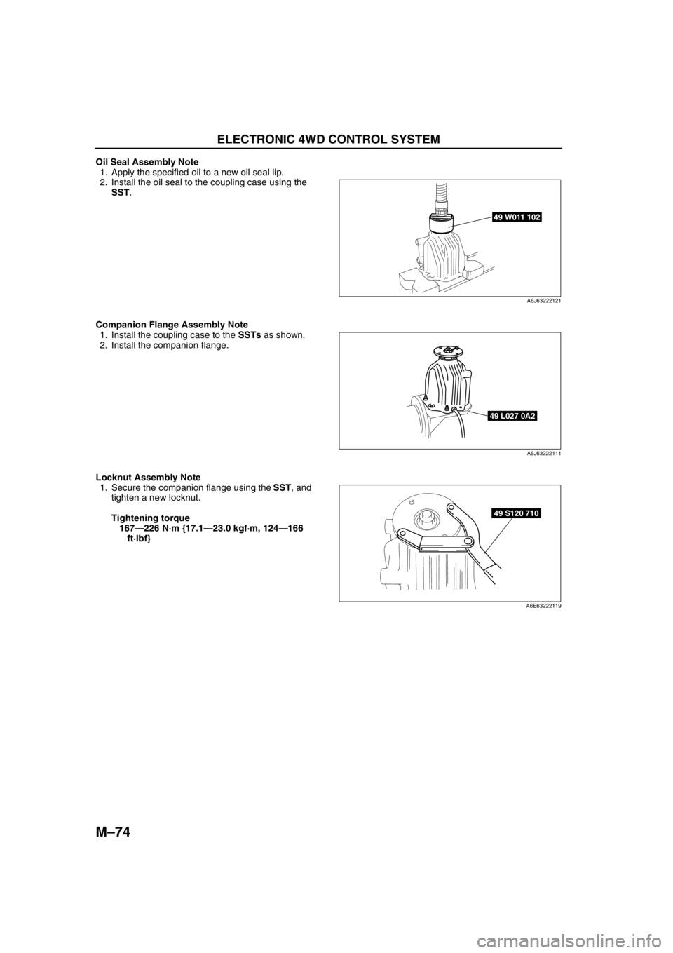
Oil Seal Assembly Note
1. Apply the specified oil to a new oil seal lip.
2. Install the oil seal to the coupling case using the
SST.
Companion Flange Assembly Note
1. Install the coupling case to the SSTs as shown.
2. Install the companion flange.
Locknut Assembly Note
1. Secure the companion flange using the SST, and
tighten a new locknut.
Tightening torque
167—226 N·m {17.1—23.0 kgf·m, 124—166
ft·lbf}
End Of Sie
49 W011 102
A6J63222121
49 L027 0A2
A6J63222111
49 S120 710
A6E63222119
Page 705 of 909

ON-BOARD DIAGNOSTIC
M–75
M
WIRING DIAGRAMA6E637027100201
End Of Sie
ON-BOARD DIAGNOSTIC
IGNITION SWITCH
BATTERY
DIFFERENTIAL OIL
TEMPERATURE
SENSOR4WD CM4WD SOLENOID ELECTRONIC CONTROL
COUPLING
CAN DRIVERINSTRUMENT CLUSTER
CAN-H
CAN-LPCM DSC HU/CM KO
P I
A
C
NH G
TCM
A6E63702002
Page 706 of 909

M–76
ON-BOARD DIAGNOSTIC
ELECTRONIC 4WD CONTROL SYSTEM ON-BOARD DIAGNOSISA6E637027100202Reading DTCs Procedure
1. Connect WDS or equivalent to the vehicle DLC-2
16-pin connector.
2. Retrieve DTC by WDS or equivalent.
•If a DTC is displayed, proceed with inspection
steps for that DTC.
3. After repair, clear DTCs stored in the 4WD CM by
referring to the Clearing DTCs Procedure.
Clearing DTCs Procedures
1. Connect WDS or equivalent to the vehicle DLC-2
16-pin connector.
2. Clear DTCs by WDS or equivalent.
3. Turn the ignition key to OFF.
4. Perform the DTC inspection again, and verify that
no DTC appears.
5. Disconnect the WDS or equivalent.
DTC Table
End Of Sie
DLC-2
DLC-2
L.H.D.
R.H.D.
A6E63702005
DLC-2
DLC-2
L.H.D.
R.H.D.
A6E63702005
DTC
Diagnosis system component Page
WDS or equivalent
P1887 System wiring (See M–77 DTC P1887)
P1888 Differential oil temperature sensor (See M–79 DTC P1888)
U0100 PCM communication (See M–80 DTC U0100)
U0101 TCM communication (See M–80 DTC U0101)
U0121 ABS/DSC communication (See M–80 DTC U0121)
Page 707 of 909
ON-BOARD DIAGNOSTIC
M–77
M
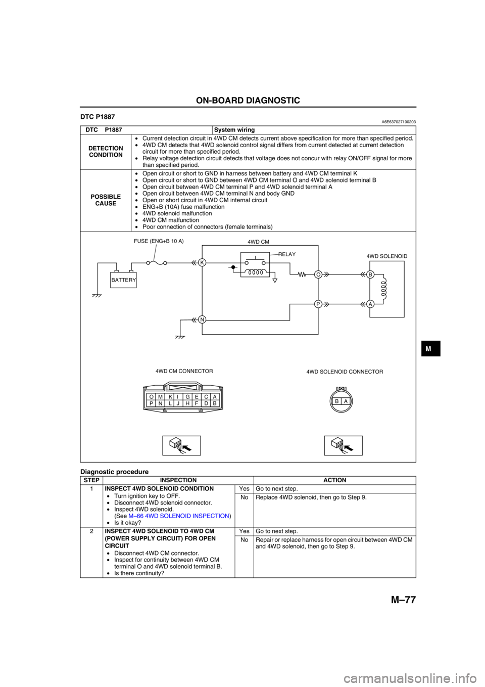
DTC P1887A6E637027100203
Diagnostic procedure
DTC P1887 System wiring
DETECTION
CONDITION•Current detection circuit in 4WD CM detects current above specification for more than specified period.
•4WD CM detects that 4WD solenoid control signal differs from current detected at current detection
circuit for more than specified period.
•Relay voltage detection circuit detects that voltage does not concur with relay ON/OFF signal for more
than specified period.
POSSIBLE
CAUSE•Open circuit or short to GND in harness between battery and 4WD CM terminal K
•Open circuit or short to GND between 4WD CM terminal O and 4WD solenoid terminal B
•Open circuit between 4WD CM terminal P and 4WD solenoid terminal A
•Open circuit between 4WD CM terminal N and body GND
•Open or short circuit in 4WD CM internal circuit
•ENG+B (10A) fuse malfunction
•4WD solenoid malfunction
•4WD CM malfunction
•Poor connection of connectors (female terminals)
STEP INSPECTION ACTION
1INSPECT 4WD SOLENOID CONDITION
•Turn ignition key to OFF.
•Disconnect 4WD solenoid connector.
•Inspect 4WD solenoid.
(See M–66 4WD SOLENOID INSPECTION)
•Is it okay?Yes Go to next step.
No Replace 4WD solenoid, then go to Step 9.
2INSPECT 4WD SOLENOID TO 4WD CM
(POWER SUPPLY CIRCUIT) FOR OPEN
CIRCUIT
•Disconnect 4WD CM connector.
•Inspect for continuity between 4WD CM
terminal O and 4WD solenoid terminal B.
•Is there continuity?Yes Go to next step.
No Repair or replace harness for open circuit between 4WD CM
and 4WD solenoid, then go to Step 9.
A A
B C
D E
F G
H I
J K
L M
N O
PB K
O B
A
N P BATTERYFUSE (ENG+B 10 A)
4WD CM
4WD CM CONNECTOR4WD SOLENOID
4WD SOLENOID CONNECTOR RELAY
Page 708 of 909

M–78
ON-BOARD DIAGNOSTIC
End Of Sie
3INSPECT 4WD SOLENOID TO 4WD CM
(POWER SUPPLY CIRCUIT) FOR SHORT TO
GROUND
•Inspect for continuity between 4WD CM
terminal O and ground.
•Is there continuity?Yes Repair or replace harness for short to ground between 4WD
CM and 4WD solenoid, then go to Step 9.
No Go to next step.
4INSPECT 4WD SOLENOID TO 4WD CM
(GROUND CIRCUIT) FOR OPEN CIRCUIT
•Inspect for continuity between 4WD CM
terminal P and 4WD solenoid terminal A.
•Is there continuity?Yes Replace 4WD CM, then go to next step.
No Repair or replace harness for open circuit between 4WD CM
and 4WD solenoid, then go to Step 9.
5INSPECT 4WD CM POWER SUPPLY CIRCUIT
FOR OPEN CIRCUIT
•Measure voltage between 4WD CM terminal
K and ground.
•Is voltage B+?Yes Replace 4WD CM, then go to Step 9.
No Go to next step.
6INSPECT 4WD CM TO BATTERY FOR OPEN
CIRCUIT
•Disconnect 4WD CM connector and battery
positive terminal.
•Inspect for continuity between 4WD CM
terminal K and battery positive terminal.
•Is there continuity?Yes Go to next step.
No Repair or replace harness for open circuit between 4WD CM
and battery positive terminal, then go to Step 9.
7INSPECT 4WD CM TO BATTERY FOR SHORT
TO GROUND
•Inspect for continuity between 4WD CM
terminal K and ground.
•Is there continuity?Yes Repair or replace harness for short to ground between 4WD
CM and battery positive terminal, then go to Step 9.
No Replace 4WD CM, then go to step 9.
8INSPECT FUSE CONDITION
•Turn ignition key to OFF.
•Is ENG+B fuse (10A) okay?Yes Go to next step.
No Replace fuse, then go to Step 9.
9VERIFY TROUBLESHOOTING COMPLETED
•Make sure to reconnect all disconnected
connectors.
•Clear DTC from memory.
(See M–76 Clearing DTCs Procedures)
•Drive vehicle.
•Is the same DTC present?Yes Replace 4WD CM, then go to next step.
No Go to next step.
10VERIFY AFTER REPAIR PROCEDURE
•Is there any other DTC present?Yes Go to applicable DTC inspection.
No Troubleshooting completed. STEP INSPECTION ACTION
Page 709 of 909

ON-BOARD DIAGNOSTIC
M–79
M
DTC P1888A6E637027100204
Diagnostic procedure
DTC P1888 Differential oil temperature sensor
DETECTION
CONDITION•Differential oil temperature sensor voltage monitor circuit detects abnormal input voltage.
POSSIBLE
CAUSE•Open circuit, or short to battery or GND between 4WD CM terminal A and differential oil temperature
sensor terminal A
•Open circuit or short to battery between 4WD CM terminal C and differential oil temperature sensor
terminal B
•Differential oil temperature sensor malfunction
•4WD CM malfunction
•Poor connection of connectors (female terminals)
STEP INSPECTION ACTION
1INSPECT DIFFERENTIAL OIL
TEMPERATURE SENSOR CONDITION
•Turn ignition key to OFF.
•Disconnect differential oil temperature
sensor connector.
•Is it okay?Yes Go to next step.
No Replace differential oil temperature sensor, then go to Step
7.
2INSPECT 4WD CM TO DIFFERENTIAL OIL
TEMPERATURE SENSOR FOR OPEN
CIRCUIT
•Disconnect 4WD CM connector.
•Inspect for continuity between 4WD CM
terminal A and differential oil temperature
sensor terminal A.
•Is there continuity?Yes Go to next step.
No Repair or replace harness for open circuit between 4WD CM
and differential oil temperature sensor, then go to Step 7.
3INSPECT 4WD CM TO DIFFERENTIAL OIL
TEMPERATURE SENSOR FOR SHORT TO
POWER
•Inspect voltage between 4WD CM terminal A
and ground.
•Is voltage B+?Yes Repair or replace harness for short to power between 4WD
CM and differential oil temperature sensor, then go to Step
7.
No Go to next step.
A B A
B C
D E
F G
H I
J K
L M
N O
PA
C A
B
4WD CM CONNECTOR4WD CM
DIFFERENTIAL OIL
TEMPERATURE SENSOR
DIFFERENTIAL OIL TEMPERATURE
SENSOR CONNECTOR
Page 710 of 909
M–80
ON-BOARD DIAGNOSTIC
End Of Sie
DTC U0100A6E637027100205
Diagnostic Procedure
•Inspect according to the diagnostic procedure in Section T. (See T–39 MULTIPLEX COMMUNICATION
SYSTEM.)
End Of Sie
DTC U0101A6E637027100206
Diagnostic Procedure
•Inspect according to the diagnostic procedure in Section T. (See T–39 MULTIPLEX COMMUNICATION
SYSTEM.)
End Of Sie
DTC U0121A6E637027100207
Diagnostic Procedure
•Inspect according to the diagnostic procedure in Section T. (See T–39 MULTIPLEX COMMUNICATION
SYSTEM.)
End Of Sie
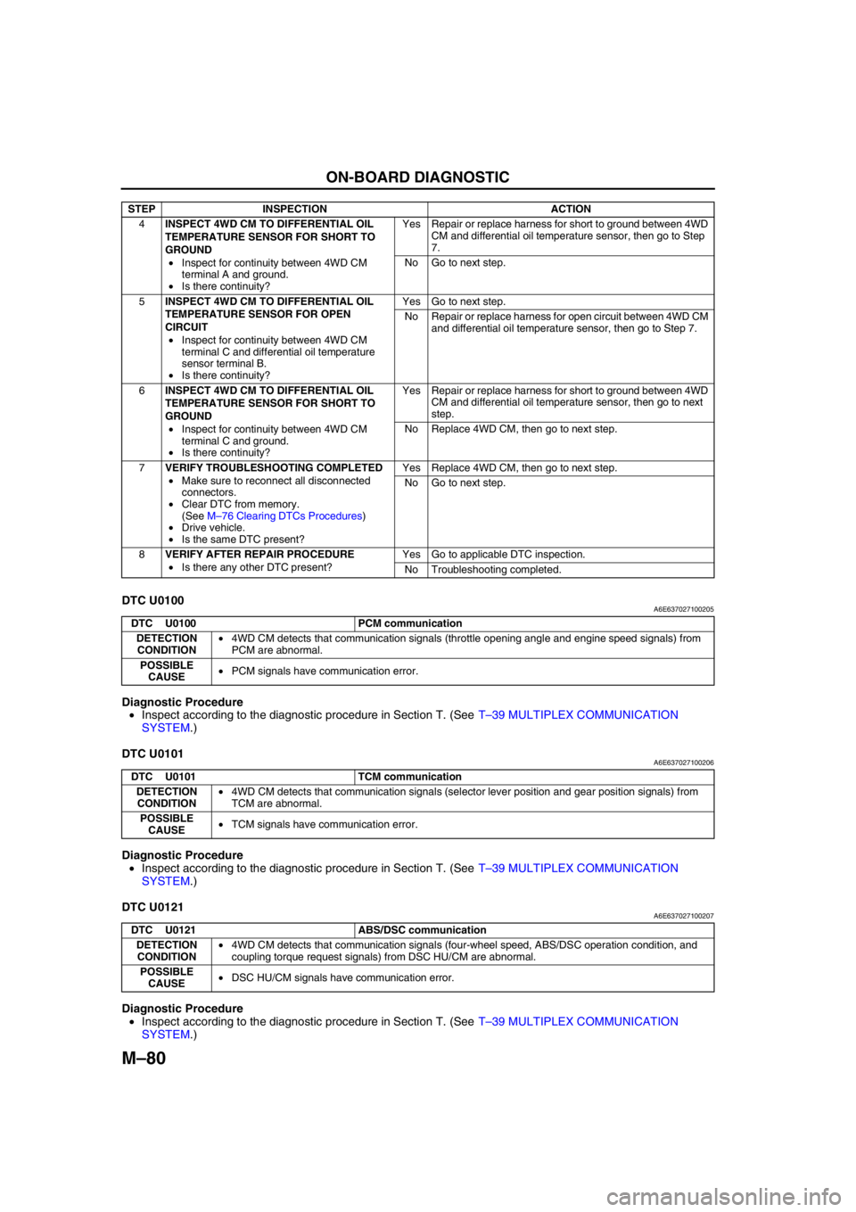
4INSPECT 4WD CM TO DIFFERENTIAL OIL
TEMPERATURE SENSOR FOR SHORT TO
GROUND
•Inspect for continuity between 4WD CM
terminal A and ground.
•Is there continuity?Yes Repair or replace harness for short to ground between 4WD
CM and differential oil temperature sensor, then go to Step
7.
No Go to next step.
5INSPECT 4WD CM TO DIFFERENTIAL OIL
TEMPERATURE SENSOR FOR OPEN
CIRCUIT
•Inspect for continuity between 4WD CM
terminal C and differential oil temperature
sensor terminal B.
•Is there continuity?Yes Go to next step.
No Repair or replace harness for open circuit between 4WD CM
and differential oil temperature sensor, then go to Step 7.
6INSPECT 4WD CM TO DIFFERENTIAL OIL
TEMPERATURE SENSOR FOR SHORT TO
GROUND
•Inspect for continuity between 4WD CM
terminal C and ground.
•Is there continuity?Yes Repair or replace harness for short to ground between 4WD
CM and differential oil temperature sensor, then go to next
step.
No Replace 4WD CM, then go to next step.
7VERIFY TROUBLESHOOTING COMPLETED
•Make sure to reconnect all disconnected
connectors.
•Clear DTC from memory.
(See M–76 Clearing DTCs Procedures)
•Drive vehicle.
•Is the same DTC present?Yes Replace 4WD CM, then go to next step.
No Go to next step.
8VERIFY AFTER REPAIR PROCEDURE
•Is there any other DTC present?Yes Go to applicable DTC inspection.
No Troubleshooting completed. STEP INSPECTION ACTION
DTC U0100 PCM communication
DETECTION
CONDITION•4WD CM detects that communication signals (throttle opening angle and engine speed signals) from
PCM are abnormal.
POSSIBLE
CAUSE•PCM signals have communication error.
DTC U0101 TCM communication
DETECTION
CONDITION•4WD CM detects that communication signals (selector lever position and gear position signals) from
TCM are abnormal.
POSSIBLE
CAUSE•TCM signals have communication error.
DTC U0121 ABS/DSC communication
DETECTION
CONDITION•4WD CM detects that communication signals (four-wheel speed, ABS/DSC operation condition, and
coupling torque request signals) from DSC HU/CM are abnormal.
POSSIBLE
CAUSE•DSC HU/CM signals have communication error.