MAZDA 6 2002 Workshop Manual Suplement
Manufacturer: MAZDA, Model Year: 2002, Model line: 6, Model: MAZDA 6 2002Pages: 909, PDF Size: 17.16 MB
Page 691 of 909
REAR DIFFERENTIAL
M–61
M
Locknut Assembly Note
Drive pinion preload adjustment
1. Apply differential oil to a new locknut.
2. Assemble a new collapsible spacer, bearing inner race (front bearing), and locknut to the drive pinion, and
temporarily tighten the locknut.
3. Turn the serrated part of the drive pinion by hand to seat the bearing.
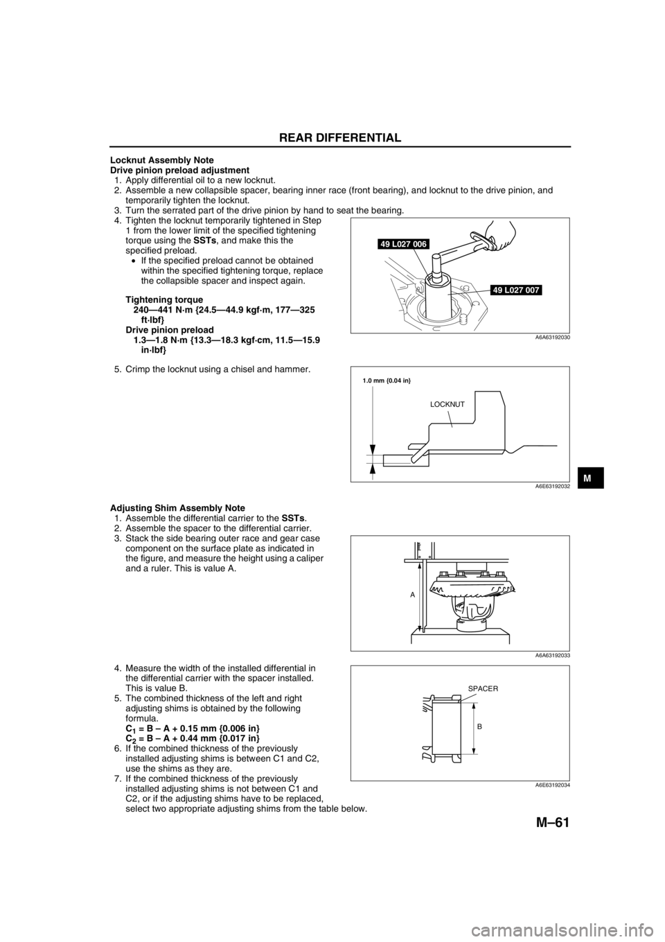
4. Tighten the locknut temporarily tightened in Step
1 from the lower limit of the specified tightening
torque using the SSTs, and make this the
specified preload.
•If the specified preload cannot be obtained
within the specified tightening torque, replace
the collapsible spacer and inspect again.
Tightening torque
240—441 N·m {24.5—44.9 kgf·m, 177—325
ft·lbf}
Drive pinion preload
1.3—1.8 N·m {13.3—18.3 kgf·cm, 11.5—15.9
in·lbf}
5. Crimp the locknut using a chisel and hammer.
Adjusting Shim Assembly Note
1. Assemble the differential carrier to the SSTs.
2. Assemble the spacer to the differential carrier.
3. Stack the side bearing outer race and gear case
component on the surface plate as indicated in
the figure, and measure the height using a caliper
and a ruler. This is value A.
4. Measure the width of the installed differential in
the differential carrier with the spacer installed.
This is value B.
5. The combined thickness of the left and right
adjusting shims is obtained by the following
formula.
C
1 = B – A + 0.15 mm {0.006 in}
C
2 = B – A + 0.44 mm {0.017 in}
6. If the combined thickness of the previously
installed adjusting shims is between C1 and C2,
use the shims as they are.
7. If the combined thickness of the previously
installed adjusting shims is not between C1 and
C2, or if the adjusting shims have to be replaced,
select two appropriate adjusting shims from the table below.
49 L027 006
49 L027 007
A6A63192030
LOCKNUT
1.0 mm {0.04 in}
A6E63192032
A
A6A63192033
B
SPACER
A6E63192034
Page 692 of 909
M–62
REAR DIFFERENTIAL
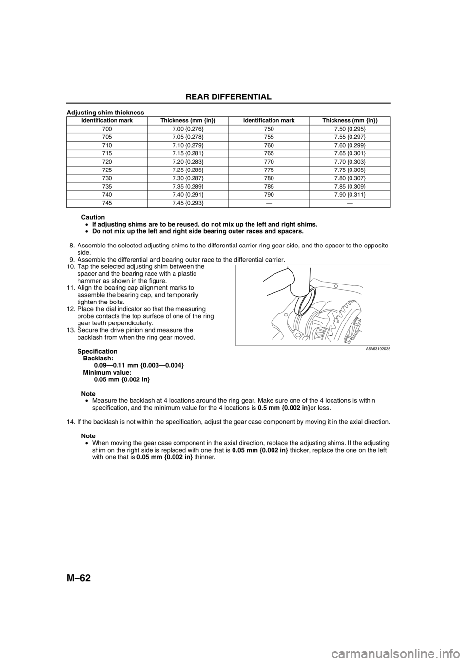
Adjusting shim thickness
Caution
•If adjusting shims are to be reused, do not mix up the left and right shims.
•Do not mix up the left and right side bearing outer races and spacers.
8. Assemble the selected adjusting shims to the differential carrier ring gear side, and the spacer to the opposite
side.
9. Assemble the differential and bearing outer race to the differential carrier.
10. Tap the selected adjusting shim between the
spacer and the bearing race with a plastic
hammer as shown in the figure.
11. Align the bearing cap alignment marks to
assemble the bearing cap, and temporarily
tighten the bolts.
12. Place the dial indicator so that the measuring
probe contacts the top surface of one of the ring
gear teeth perpendicularly.
13. Secure the drive pinion and measure the
backlash from when the ring gear moved.
Specification
Backlash:
0.09—0.11 mm {0.003—0.004}
Minimum value:
0.05 mm {0.002 in}
Note
•Measure the backlash at 4 locations around the ring gear. Make sure one of the 4 locations is within
specification, and the minimum value for the 4 locations is 0.5 mm {0.002 in}or less.
14. If the backlash is not within the specification, adjust the gear case component by moving it in the axial direction.
Note
•When moving the gear case component in the axial direction, replace the adjusting shims. If the adjusting
shim on the right side is replaced with one that is 0.05 mm {0.002 in} thicker, replace the one on the left
with one that is 0.05 mm {0.002 in} thinner.
Identification mark Thickness (mm {in}) Identification mark Thickness (mm {in})
700 7.00 {0.276} 750 7.50 {0.295}
705 7.05 {0.278} 755 7.55 {0.297}
710 7.10 {0.279} 760 7.60 {0.299}
715 7.15 {0.281} 765 7.65 {0.301}
720 7.20 {0.283} 770 7.70 {0.303}
725 7.25 {0.285} 775 7.75 {0.305}
730 7.30 {0.287} 780 7.80 {0.307}
735 7.35 {0.289} 785 7.85 {0.309}
740 7.40 {0.291} 790 7.90 {0.311}
745 7.45 {0.293}——
A6A63192035
Page 693 of 909
REAR DIFFERENTIAL
M–63
M
Bearing Cap Assembly Note
1. Align the bearing cap alignment marks to assemble the bearing cap.
Tightening torque
37—51 N·m {3.8—5.2 kgf·m, 28—37 ft·lbf}
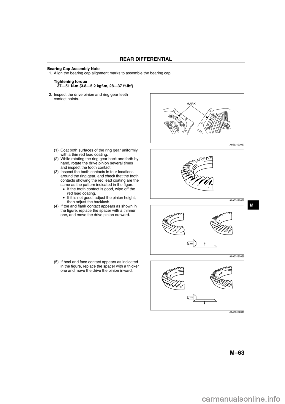
2. Inspect the drive pinion and ring gear teeth
contact points.
(1) Coat both surfaces of the ring gear uniformly
with a thin red lead coating.
(2) While rotating the ring gear back and forth by
hand, rotate the drive pinion several times
and inspect the tooth contact.
(3) Inspect the tooth contacts in four locations
around the ring gear, and check that the tooth
contacts showing the red lead coating are the
same as the pattern indicated in the figure.
•If the tooth contact is good, wipe off the
red lead coating.
•If it is not good, adjust the pinion height,
then adjust the backlash.
(4) If toe and flank contact appears as shown in
the figure, replace the spacer with a thinner
one, and move the drive pinion outward.
(5) If heel and face contact appears as indicated
in the figure, replace the spacer with a thicker
one and move the drive the pinion inward.
MARK
A6E63192037
A6A63192038
A6A63192039
A6A63192040
Page 694 of 909
M–64
REAR DIFFERENTIAL
Rear Cover Assembly Note
Caution
•Clean away the old sealant before applying the new sealant.
•Install the rear differential within 10 minutes after applying sealant.
•Allow the sealant to set at least 30 minutes after installation before filling the differential with the
specified oil.
1. Clean the alignment surface of the carrier and rear cover, and apply a thin coat of sealant.
2. Install the rear cover.
Tightening torque
15.7—22.6 N·m {1.6—2.3 kgf·m, 11.6—16.6 ft·lbf}
Oil Seal Assembly Note
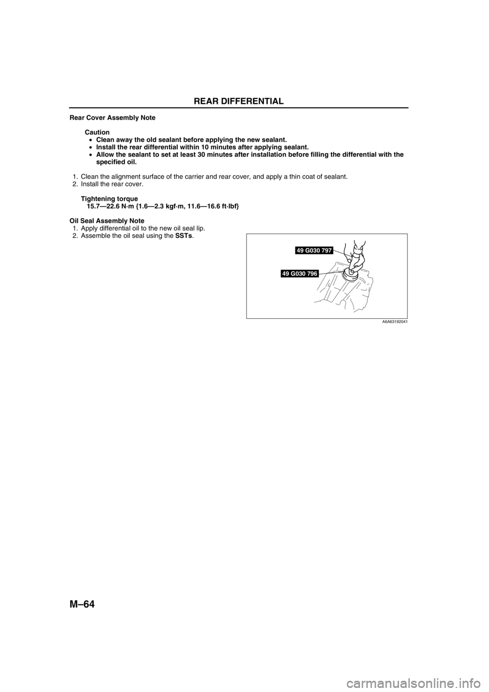
1. Apply differential oil to the new oil seal lip.
2. Assemble the oil seal using the SSTs.
End Of Sie
49 G030 796
49 G030 797
A6A63192041
Page 695 of 909
ELECTRONIC 4WD CONTROL SYSTEM
M–65
M
DIFFERENTIAL OIL TEMPERATURE SENSOR INSPECTIONA6E632227100209
Warning
•Hot differential oil may cause severe burns. Do not perform maintenance while differential oil is
hot.
1. Disconnect the negative (-) battery cable.
2. Disconnect the differential oil temperature sensor connector and remove the differential oil temperature sensor.
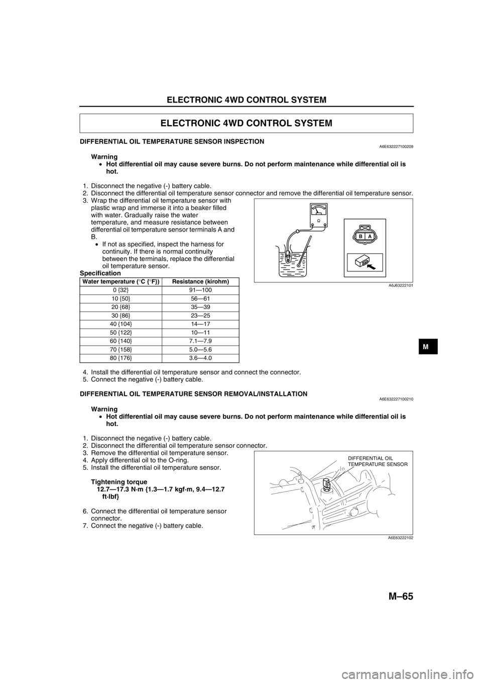
3. Wrap the differential oil temperature sensor with
plastic wrap and immerse it into a beaker filled
with water. Gradually raise the water
temperature, and measure resistance between
differential oil temperature sensor terminals A and
B.
•If not as specified, inspect the harness for
continuity. If there is normal continuity
between the terminals, replace the differential
oil temperature sensor.
Specification
4. Install the differential oil temperature sensor and connect the connector.
5. Connect the negative (-) battery cable.
End Of Sie
DIFFERENTIAL OIL TEMPERATURE SENSOR REMOVAL/INSTALLATIONA6E632227100210
Warning
•Hot differential oil may cause severe burns. Do not perform maintenance while differential oil is
hot.
1. Disconnect the negative (-) battery cable.
2. Disconnect the differential oil temperature sensor connector.
3. Remove the differential oil temperature sensor.
4. Apply differential oil to the O-ring.
5. Install the differential oil temperature sensor.
Tightening torque
12.7—17.3 N·m {1.3—1.7 kgf·m, 9.4—12.7
ft·lbf}
6. Connect the differential oil temperature sensor
connector.
7. Connect the negative (-) battery cable.
End Of Sie
ELECTRONIC 4WD CONTROL SYSTEM
Water temperature (°C {°F}) Resistance (kirohm)
0 {32} 91—100
10 {50} 56—61
20 {68} 35—39
30 {86} 23—25
40 {104} 14—17
50 {122} 10—11
60 {140} 7.1—7.9
70 {158} 5.0—5.6
80 {176} 3.6—4.0
A B
A6J63222101
DIFFERENTIAL OIL
TEMPERATURE SENSOR
A6E63222102
Page 696 of 909
M–66
ELECTRONIC 4WD CONTROL SYSTEM
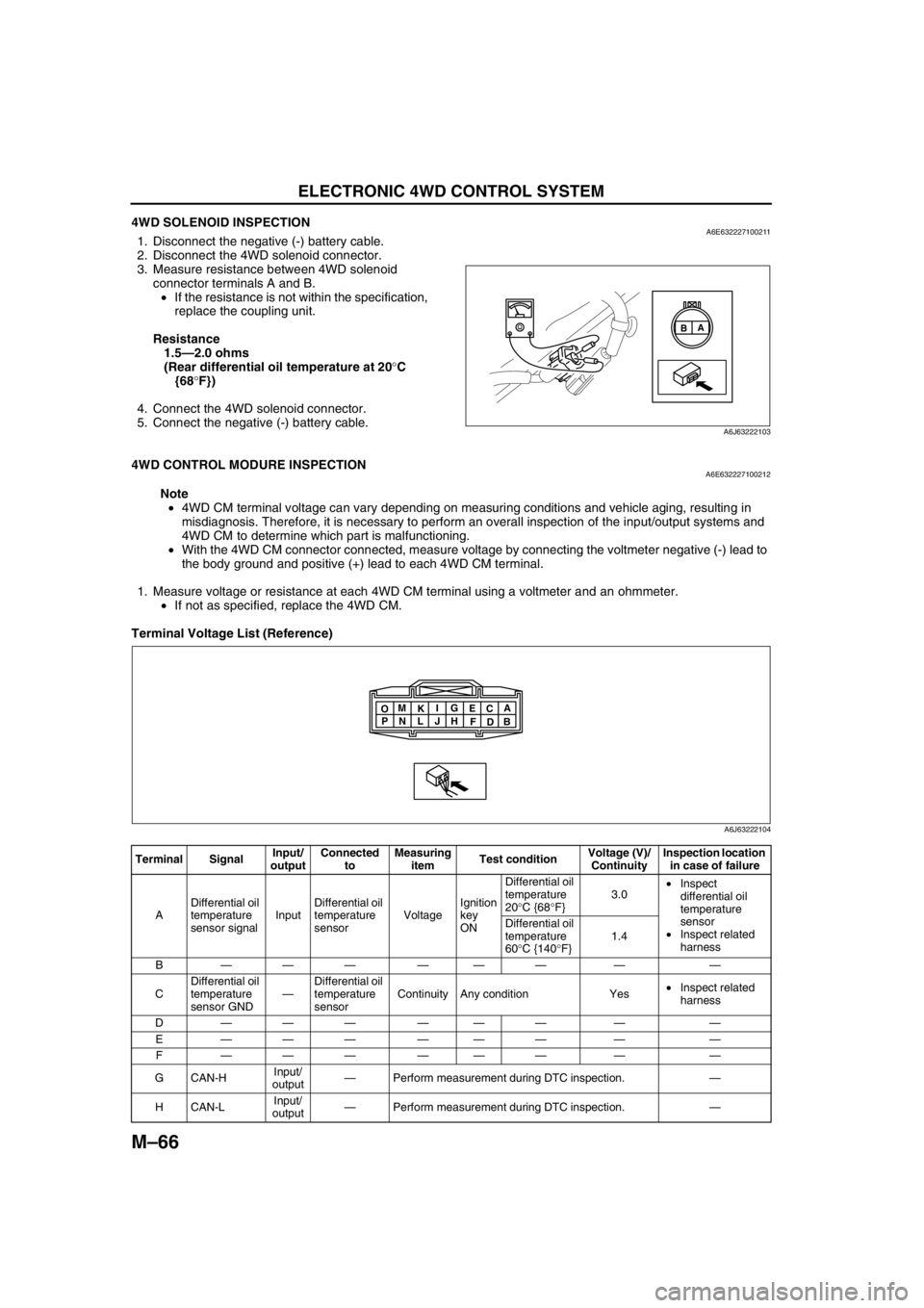
4WD SOLENOID INSPECTIONA6E6322271002111. Disconnect the negative (-) battery cable.
2. Disconnect the 4WD solenoid connector.
3. Measure resistance between 4WD solenoid
connector terminals A and B.
•If the resistance is not within the specification,
replace the coupling unit.
Resistance
1.5—2.0 ohms
(Rear differential oil temperature at 20°C
{68°F})
4. Connect the 4WD solenoid connector.
5. Connect the negative (-) battery cable.
End Of Sie
4WD CONTROL MODURE INSPECTIONA6E632227100212
Note
•4WD CM terminal voltage can vary depending on measuring conditions and vehicle aging, resulting in
misdiagnosis. Therefore, it is necessary to perform an overall inspection of the input/output systems and
4WD CM to determine which part is malfunctioning.
•With the 4WD CM connector connected, measure voltage by connecting the voltmeter negative (-) lead to
the body ground and positive (+) lead to each 4WD CM terminal.
1. Measure voltage or resistance at each 4WD CM terminal using a voltmeter and an ohmmeter.
•If not as specified, replace the 4WD CM.
Terminal Voltage List (Reference)
A
B
A6J63222103
Terminal SignalInput/
outputConnected
toMeasuring
itemTest conditionVoltage (V)/
ContinuityInspection location
in case of failure
ADifferential oil
temperature
sensor signalInputDifferential oil
temperature
sensorVoltageIgnition
key
ONDifferential oil
temperature
20°C {68°F}3.0•Inspect
differential oil
temperature
sensor
•Inspect related
harness Differential oil
temperature
60°C {140°F}1.4
B——— ——— — —
CDifferential oil
temperature
sensor GND—Differential oil
temperature
sensorContinuity Any condition Yes•Inspect related
harness
D——— ——— — —
E——— ——— — —
F——— ——— — —
GCAN-HInput/
output—Perform measurement during DTC inspection.—
HCAN-LInput/
output—Perform measurement during DTC inspection.—
A
B C
D E
F G
H I
J K
L M
N O
P
A6J63222104
Page 697 of 909
ELECTRONIC 4WD CONTROL SYSTEM
M–67
M
End Of Sie
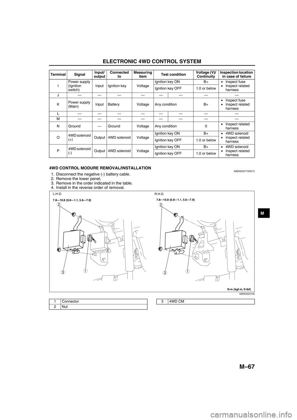
4WD CONTROL MODURE REMOVAL/INSTALLATIONA6E6322271002131. Disconnect the negative (-) battery cable.
2. Remove the lower panel.
3. Remove in the order indicated in the table.
4. Install in the reverse order of removal.
.
End Of Sie
IPower supply
(Ignition
switch)Input Ignition key VoltageIgnition key ON B+•Inspect fuse
•Inspect related
harness Ignition key OFF 1.0 or below
J——— ——— — —
KPower supply
(Main)Input Battery Voltage Any condition B+•Inspect fuse
•Inspect related
harness
L——— ——— — —
M——— ——— — —
N Ground—Ground Voltage Any condition 0•Inspect related
harness
O4WD solenoid
(+)Output 4WD solenoid VoltageIgnition key ON B+•4WD solenoid
•Inspect related
harness Ignition key OFF 1.0 or below
P4WD solenoid
(-)Output 4WD solenoid VoltageIgnition key ON B+•4WD solenoid
•Inspect related
harness Ignition key OFF 1.0 or below Terminal SignalInput/
outputConnected
toMeasuring
itemTest conditionVoltage (V)/
ContinuityInspection location
in case of failure
31
2
31
2
7.8—10.8 {0.8—1.1, 5.6—7.9}
N·m {kgf·m, ft·lbf} 7.8—10.8 {0.8—1.1, 5.6—7.9}
L.H.D.
R.H.D.
A6E63222105
1 Connector
2Nut34WD CM
Page 698 of 909
M–68
ELECTRONIC 4WD CONTROL SYSTEM
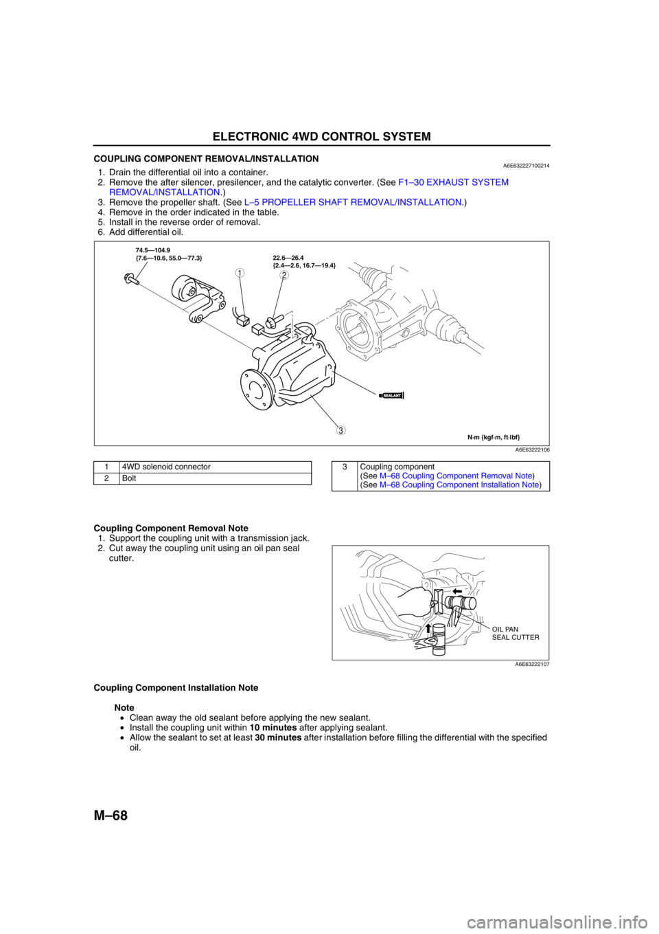
COUPLING COMPONENT REMOVAL/INSTALLATIONA6E6322271002141. Drain the differential oil into a container.
2. Remove the after silencer, presilencer, and the catalytic converter. (See F1–30 EXHAUST SYSTEM
REMOVAL/INSTALLATION.)
3. Remove the propeller shaft. (See L–5 PROPELLER SHAFT REMOVAL/INSTALLATION.)
4. Remove in the order indicated in the table.
5. Install in the reverse order of removal.
6. Add differential oil.
.
Coupling Component Removal Note
1. Support the coupling unit with a transmission jack.
2. Cut away the coupling unit using an oil pan seal
cutter.
Coupling Component Installation Note
Note
•Clean away the old sealant before applying the new sealant.
•Install the coupling unit within 10 minutes after applying sealant.
•Allow the sealant to set at least 30 minutes after installation before filling the differential with the specified
oil.
3
12
SEALANTSEALANT
74.5—104.9
{7.6—10.6, 55.0—77.3}22.6—26.4
{2.4—2.6, 16.7—19.4}
N·m {kgf·m, ft·lbf}
A6E63222106
1 4WD solenoid connector
2Bolt3 Coupling component
(See M–68 Coupling Component Removal Note)
(See M–68 Coupling Component Installation Note)
OIL PAN
SEAL CUTTER
A6E63222107
Page 699 of 909
ELECTRONIC 4WD CONTROL SYSTEM
M–69
M
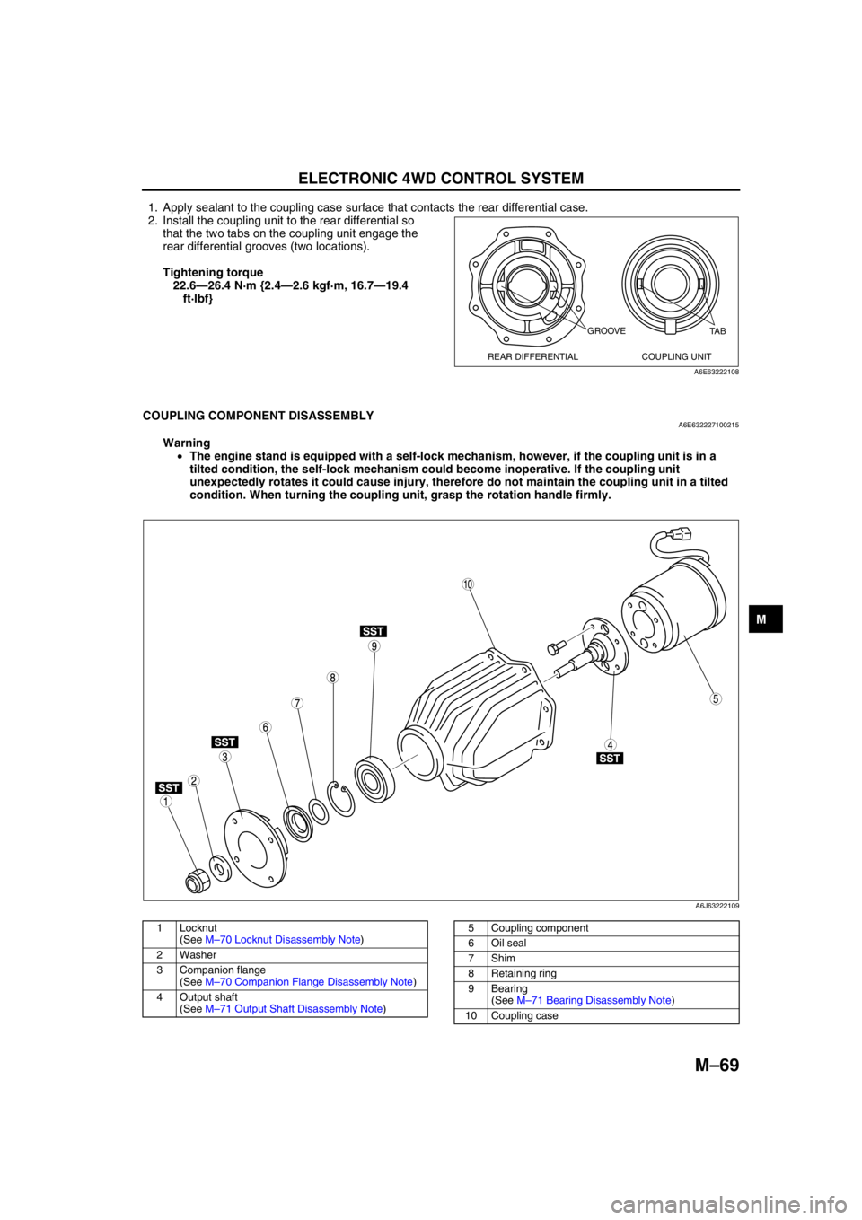
1. Apply sealant to the coupling case surface that contacts the rear differential case.
2. Install the coupling unit to the rear differential so
that the two tabs on the coupling unit engage the
rear differential grooves (two locations).
Tightening torque
22.6—26.4 N·m {2.4—2.6 kgf·m, 16.7—19.4
ft·lbf}
End Of Sie
COUPLING COMPONENT DISASSEMBLYA6E632227100215
Warning
•The engine stand is equipped with a self-lock mechanism, however, if the coupling unit is in a
tilted condition, the self-lock mechanism could become inoperative. If the coupling unit
unexpectedly rotates it could cause injury, therefore do not maintain the coupling unit in a tilted
condition. When turning the coupling unit, grasp the rotation handle firmly.
.
GROOVE
REAR DIFFERENTIAL COUPLING UNITTA B
A6E63222108
SST
SST
SST
SST
9
8
75
4
3
1
2
10
6
A6J63222109
1 Locknut
(See M–70 Locknut Disassembly Note)
2Washer
3 Companion flange
(See M–70 Companion Flange Disassembly Note)
4 Output shaft
(See M–71 Output Shaft Disassembly Note)5 Coupling component
6Oil seal
7Shim
8 Retaining ring
9 Bearing
(See M–71 Bearing Disassembly Note)
10 Coupling case
Page 700 of 909
M–70
ELECTRONIC 4WD CONTROL SYSTEM
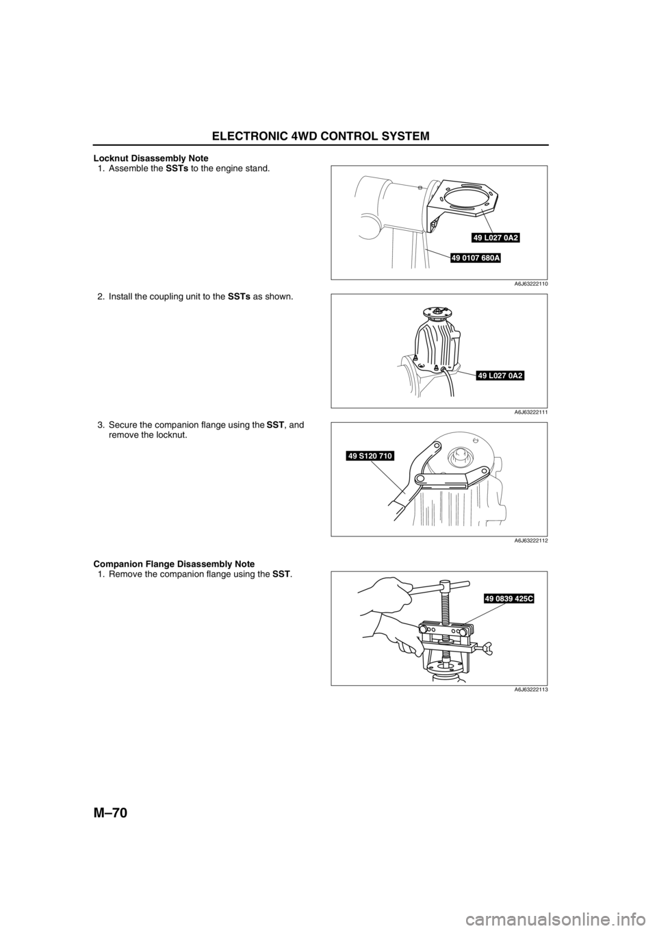
Locknut Disassembly Note
1. Assemble the SSTs to the engine stand.
2. Install the coupling unit to the SSTs as shown.
3. Secure the companion flange using the SST, and
remove the locknut.
Companion Flange Disassembly Note
1. Remove the companion flange using the SST.
49 L027 0A2
49 0107 680A
A6J63222110
49 L027 0A2
A6J63222111
49 S120 710
A6J63222112
49 0839 425C
A6J63222113