engine MAZDA 626 1987 Workshop Manual
[x] Cancel search | Manufacturer: MAZDA, Model Year: 1987, Model line: 626, Model: MAZDA 626 1987Pages: 1865, PDF Size: 94.35 MB
Page 520 of 1865
4B FUEL SYSTEM
76G04B-078
76G04B-079
Insulator
Injector
Grommet
Delivery
pipe
Pressure regulator
76G04B-080
Injector O-ring Correct
1 #J
Grommet Delivery pipe
Wrong
£a
/
^ Wrong IF
Injector
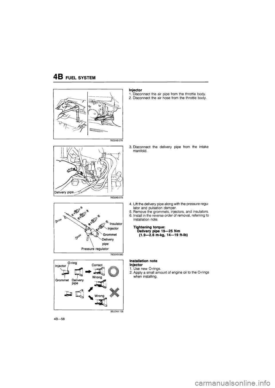
1. Disconnect the air pipe from the throttle body.
2. Disconnect the air hose from the throttle body.
3. Disconnect the delivery pipe from the intake
manifold.
4. Lift the delivery pipe along with the pressure regu-
lator and pulsation damper.
5. Remove the grommets, injectors, and insulators.
6. Install in the reverse order of removal, referring to
installation note.
Tightening torque:
Delivery pipe 19—25 N-m
(1.9—2.6 m-kg, 14—19 ft-lb)
Installation note
Injector
1. Use new O-rings.
2. Apply a small amount of engine oil to the O-rings
when installing.
86U04A-108
4B-58
Page 526 of 1865

4B DECELERATION CONTROL SYSTEM
DECELERATION CONTROL SYSTEM
This system consists of the dashpot and fuel cut system. The dashpot is to prevent after-burn so that
the throttle valve gradually closes during deceleration.
The control unit detects engine deceleration judging from the engine speed and the idle switch, and
signals a fuel cut operation to match the engines need, based on the coolant temperature and the
driving condition.
4B—64
Page 527 of 1865

DECELERATION CONTROL SYSTEM 4B
COMPONENT DESCRIPTIONS
Component Function Remarks
Brake light switch Detects braking operation (deceleration);
sends signal to engine control unit
Clutch switch Detects in-gear condition;
sends signal to engine control unit Switch ON when clutch pedal released
Dashpot (MTX) Prevents sudden closing of throttle valve during deceleration or shifting Adjustment speed: 1,900—2,100 rpm
Engine control unit Detects signals from input sensors and switches; cuts fuel injection
Idle switch Detects when throttle valve fully closed; sends signal to engine control unit Installed in throttle sensor
Ignition coil (-) terminal Detects engine speed; sends signal to engine control unit
Neutral switch Detects in-gear condition; sends signal to engine control unit Switch ON when in-gear
Water thermo sensor Detects coolant temperature; sends signal to engine control unit
Water thermo switch Detects radiator coolant temperature; sends signal to engine control unit ON: above 17°C (63°F)
76G04B-089
4B—65
Page 528 of 1865
4B DECELERATION CONTROL SYSTEM
TROUBLESHOOTING
Check the condition of the wiring harness and connectors before checking the sensor or switches below.
Note
Make the system inspection first. If no problem is found, continue with the next system
inspection of the Troubleshooting Guide. (Refer to page 4B—7 and 8.)
Possible
^^ cause
Symptom
Dashpot Water thermo
sensor
Electrical signal
inspection
(Injector)
Possible
^^ cause
Symptom 4B—67 4B—97 4B-66
High idle speed after warming up 1
Runs rough on deceleration 1 3 2
Afterburn in exhaust system 1 3 2
Poor fuel consumption 1 3 2
Fails emission test 1 3 2
76G04B-090
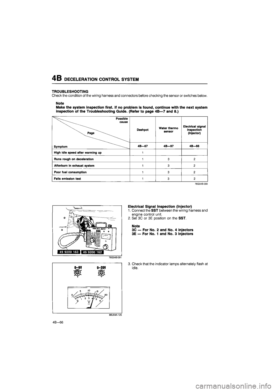
Electrical Signal Inspection (Injector)
1. Connect the SST between the wiring harness and
engine control unit.
2. Set 3C or 3E position on the SST.
Note
3C — For No. 2 and No. 4 injectors
3E — For No. 1 and No. 3 injectors
76G04B-091
0-6V 0-20V
3. Check that the indicator lamps alternately flash at
idle.
86U04A-125
4B—66
Page 529 of 1865
DECELERATION CONTROL SYSTEM 4B
86U04A-126
76G04B-092
76G04B-093
Lock nutLg*
rJpM
Lever-V- y"
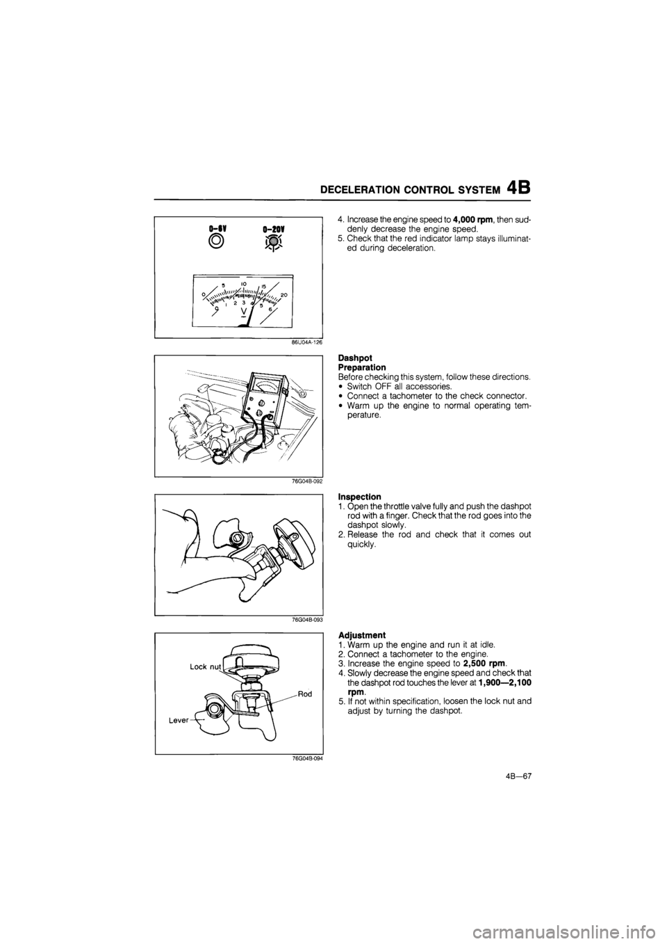
4. Increase the engine speed to 4,000 rpm, then sud-
denly decrease the engine speed.
5. Check that the red indicator lamp stays illuminat-
ed during deceleration.
Dashpot
Preparation
Before checking this system, follow these directions.
• Switch OFF all accessories.
• Connect a tachometer to the check connector.
• Warm up the engine to normal operating tem-
perature.
Inspection
1. Open the throttle valve fully and push the dashpot
rod with a finger. Check that the rod goes into the
dashpot slowly.
2. Release the rod and check that it comes out
quickly.
Adjustment
1. Warm up the engine and run it at idle.
2. Connect a tachometer to the engine.
3. Increase the engine speed to 2,500 rpm.
4. Slowly decrease the engine speed and check that
the dashpot rod touches the lever at 1,900—2,100
rpm.
5. If not within specification, loosen the lock nut and
adjust by turning the dashpot.
76G04B-094
4B-67
Page 531 of 1865
AIR INJECTION SYSTEM 4B
TROUBLESHOOTING
Check the condition of the wiring harness and connectors before checking the sensors or switch.
Note
Make the system inspection first. If no problem is found, continue with the next system
inspection of the Troubleshooting Guide. (Refer to pages 4B—7 and 8.)
Possible cause Air control valve Reed valve System inspection
Page 4B—69 4B—70 4B—69
Checking order 2 3 1
76G04B-097
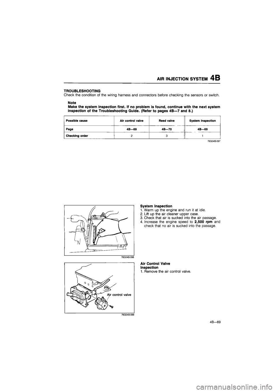
System Inspection
1. Warm up the engine and run it at idle.
2. Lift up the air cleaner upper case.
3. Check that air is sucked into the air passage.
4. Increase the engine speed to 2,500 rpm and
check that no air is sucked into the passage.
Air Control Valve
Inspection
1. Remove the air control valve.
4B-69
Page 532 of 1865
4B AIR INJECTION SYSTEM
56G04B-114p
76G04B-100
76U04A-066
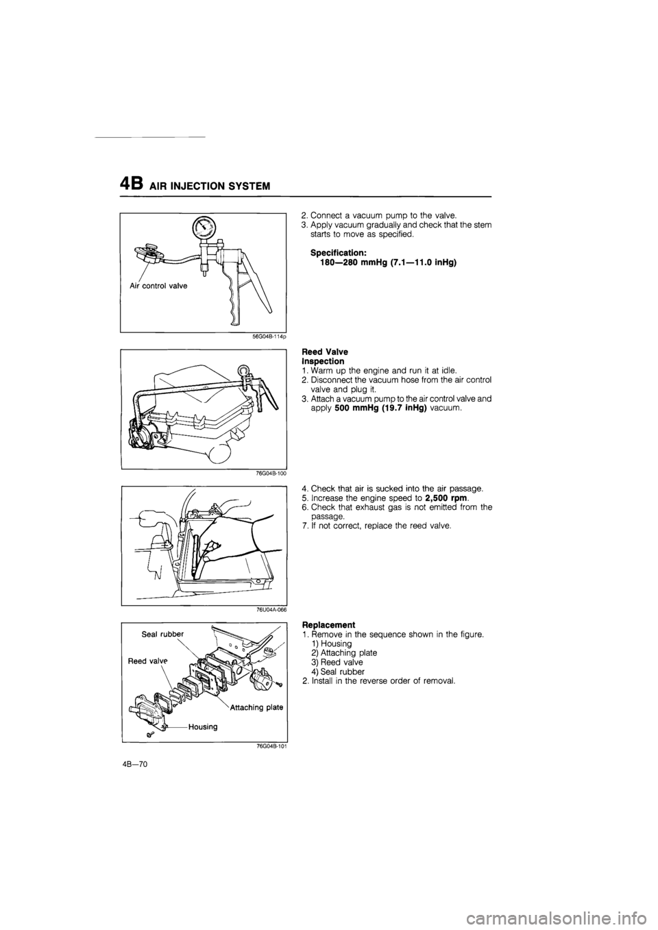
2. Connect a vacuum pump to the valve.
3. Apply vacuum gradually and check that the stem
starts to move as specified.
Specification:
180—280 mmHg (7.1—11.0 inHg)
Reed Valve
Inspection
1. Warm up the engine and run it at idle.
2. Disconnect the vacuum hose from the air control
valve and plug it.
3. Attach a vacuum pump to the air control valve and
apply 500 mmHg (19.7 inHg) vacuum.
4. Check that air is sucked into the air passage.
5. Increase the engine speed to 2,500 rpm.
6. Check that exhaust gas is not emitted from the
passage.
7. If not correct, replace the reed valve.
Replacement
1. Remove in the sequence shown in the figure.
1) Housing
2) Attaching plate
3) Reed valve
4) Seal rubber
2. Install in the reverse order of removal.
76G04B-101
4B—70
Page 533 of 1865

EGR SYSTEM 4B
EXHAUST GAS RECIRCULATION
(EGR)
SYSTEM
EGR modulator valve Solenoid valve (EGR)
86U04A-127
This system introduces exhaust gas into the intake manifold to reduce NOx in the exhaust gas. It oper-
ates depending on the engine load, engine speed (above 1,500 rpm), engine coolant temperature
(above 70°C, 158°F), and radiator coolant temperature (above 17°C, 63°F).
COMPONENT DESCRIPTIONS
Component Function Remarks
EGR control valve Recirculates portion of exhaust gas
EGR modulator valve Controls vacuum acting on EGR control
valve
Engine control unit Detects signals from input sensors and switches; controls solenoid valve (EGR)
Ignition coil (-) terminal Detects engine speed; sends signal to engine control unit
Solenoid valve (EGR) Controls vacuum line to EGR control
valve
Throttle sensor Detects throttle valve opening angle; sends signal to engine control unit Integrated idle switch
Water thermo sensor Detects coolant temperature; sends signal to engine control unit
Water thermo switch Detects radiator coolant temperature; sends signal to engine control unit
ON: above 17°C (63°F)
76G04B-102
4B-71
Page 534 of 1865
4B EGR SYSTEM
TROUBLESHOOTING
Check the condition of the wiring harness and connectors before checking the sensors or switches below.
Note
Make the system inspection first. If no problem is found, continue with the next system
inspection of the Troubleshooting Guide. (Refer to pages 4B—7 and 8.)
Possible cause
Solenoid
valve (EGR)
EGR modula-tor valve
EGR con-trol valve
Water
thermo sensor
Water
thermo switch
Engine control unit
terminal
System in-spection
2N
Page 4B—72 4B—73 4B—73 4B—97 4B—97 4B—90 4B—72
Checking order 3 2 4 6 5 7 1
76G04B-103
86U04A-130
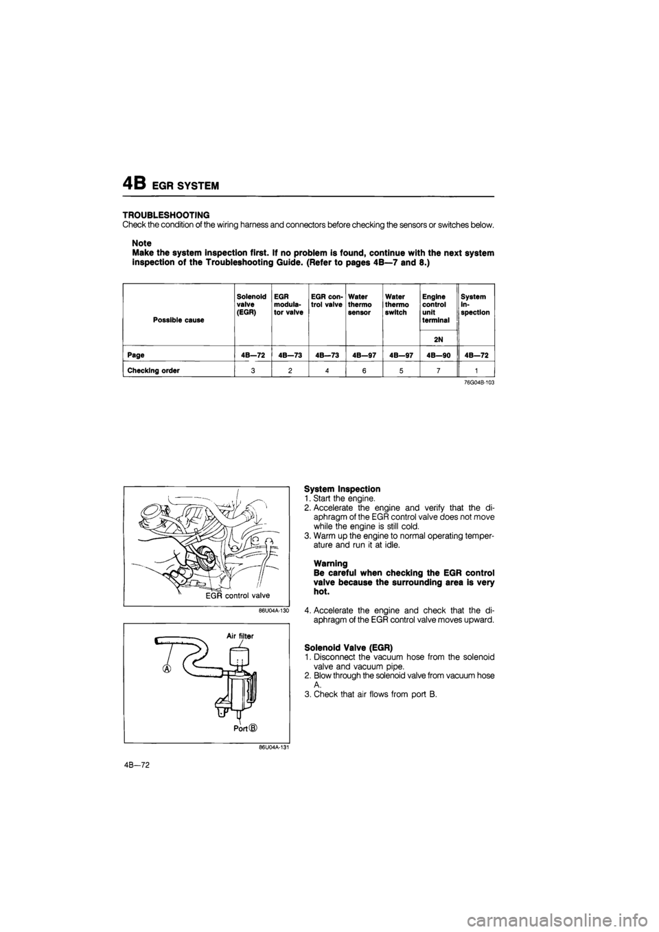
System Inspection
1. Start the engine.
2. Accelerate the engine and verify that the di-
aphragm of the EGR control valve does not move
while the engine is still cold.
3. Warm up the engine to normal operating temper-
ature and run it at idle.
Warning
Be careful when checking the EGR control
valve because the surrounding area is very
hot.
4. Accelerate the engine and check that the di-
aphragm of the EGR control valve moves upward.
Solenoid Valve (EGR)
1. Disconnect the vacuum hose from the solenoid
valve and vacuum pipe.
2. Blow through the solenoid valve from vacuum hose
A.
3. Check that air flows from port B.
86U04A-131
4B-72
Page 535 of 1865
EGR SYSTEM 4B
Apply 12V
Air filter
L
Jt Port
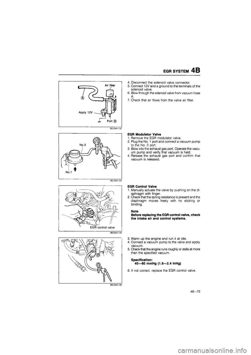
4. Disconnect the solenoid valve connector.
5. Connect 12V and a ground to the terminals of the
solenoid valve.
6. Blow through the solenoid valve from vacuum hose
A.
7. Check that air flows from the valve air filter.
86U04A-132
86U04A-133
86U04A-134
EGR Modulator Valve
1. Remove the EGR modulator valve.
2. Plug the No. 1 port and connect a vacuum pump
to the No. 3 port.
3. Blow into the exhaust gas port. Operate the vacu-
um pump and verify that vacuum is held.
4. Release the exhaust gas port and confirm that
vacuum is released.
EGR Control Valve
1. Manually actuate the valve by pushing on the di-
aphragm with finger.
2. Check that the spring resistance is present and the
diaphragm moves freely with no sticking or
binding.
Note
Before replacing the EGR control valve, check
the intake air and control systems.
3. Warm up the engine and run it at idle.
4. Connect a vacuum pump to the valve and apply
vacuum.
5. Check that the engine runs roughly or stalls at more
than the specified vacuum.
Specification:
40—60 mmHg (1.6—2.4 inHg)
6. If not correct, replace the EGR control valve.
86U04A-135
4B-73