engine MAZDA 626 1987 Workshop Manual
[x] Cancel search | Manufacturer: MAZDA, Model Year: 1987, Model line: 626, Model: MAZDA 626 1987Pages: 1865, PDF Size: 94.35 MB
Page 536 of 1865

4B EEC SYSTEM
EVAPORATIVE EMISSION CONTROL
(EEC)
SYSTEM
Engine control unit
Solenoid valve
(Purge control)
Vacuum
switch
valve x
From water thermo valve To dynamic -chamber
Three-way
check valve
Orifice Charcoal
canister
From fuel tank
No.2 purge
control valve
Fuel tank
86U04A-136
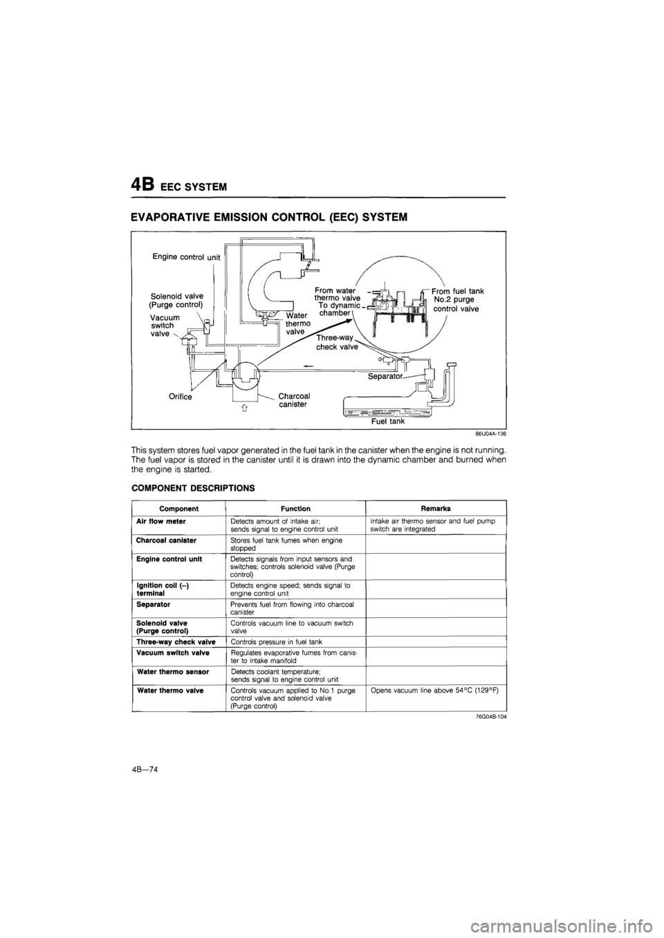
This system stores fuel vapor generated in the fuel tank in the canister when the engine is not running.
The fuel vapor is stored in the canister until it is drawn into the dynamic chamber and burned when
the engine is started.
COMPONENT DESCRIPTIONS
Component Function Remarks
Air flow meter Detects amount of intake air; sends signal to engine control unit
Intake air thermo sensor and fuel pump
switch are integrated
Charcoal canister Stores fuel tank fumes when engine
stopped
Engine control unit Detects signals from input sensors and switches; controls solenoid valve (Purge control)
Ignition coil (-)
terminal Detects engine speed; sends signal to
engine control unit
Separator Prevents fuel from flowing into charcoal canister
Solenoid valve (Purge control) Controls vacuum line to vacuum switch valve
Three-way check valve Controls pressure in fuel tank
Vacuum switch valve Regulates evaporative fumes from canis-
ter to intake manifold
Water thermo sensor Detects coolant temperature; sends signal to engine control unit
Water thermo valve Controls vacuum applied to No.1 purge control valve and solenoid valve (Purge control)
Opens vacuum line above 54°C (129°F)
76G04B-104
4B—74
Page 537 of 1865

EEC SYSTEM
4B
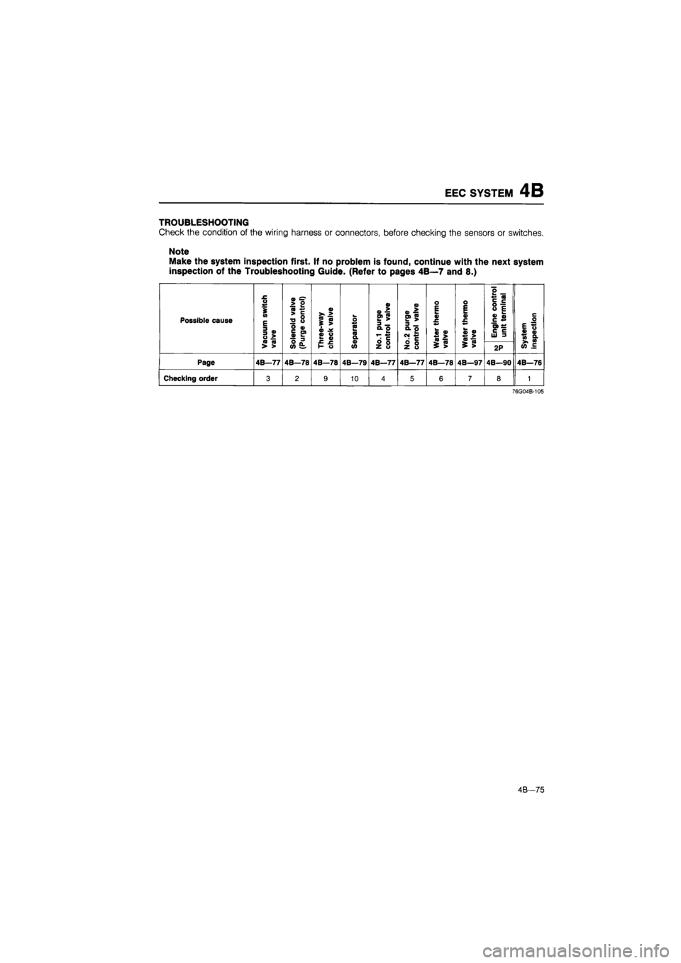
TROUBLESHOOTING
Check
the
condition
of the
wiring harness
or
connectors, before checking
the
sensors
or
switches.
Note
Make the system inspection first.
If no
problem
is
found, continue with
the
next system
inspection
of the
Troubleshooting Guide. (Refer
to
pages 4B—7 and
8.)
Possible cause
Vacuum
switch
valve
Solenoid
valve
(Purge
control)
0)
<0
m
i
>
« «
o
•C
?
o ** «0 a a
No.1
purge
control
valve
No.2
purge
control
valve
Water
thermo
valve
o E tm 0) £
«>
0)
^
>
Engine
control
unit
terminal
System inspection Vacuum
switch
valve
Solenoid
valve
(Purge
control)
purge
control
valve
No.2
purge
control
valve
Water
thermo
valve
$
>
2P
System inspection
Page 4B—77 4B—78 4B—78 4B—79 4B—77 4B—77 4B—78 4B—97 4B—90 4B—76
Checking order 3 2 9 10 4 5 6 7 8 1
76G04B-105
4B—75
Page 538 of 1865

4B EEC SYSTEM
86U04A-139
86U04A-141
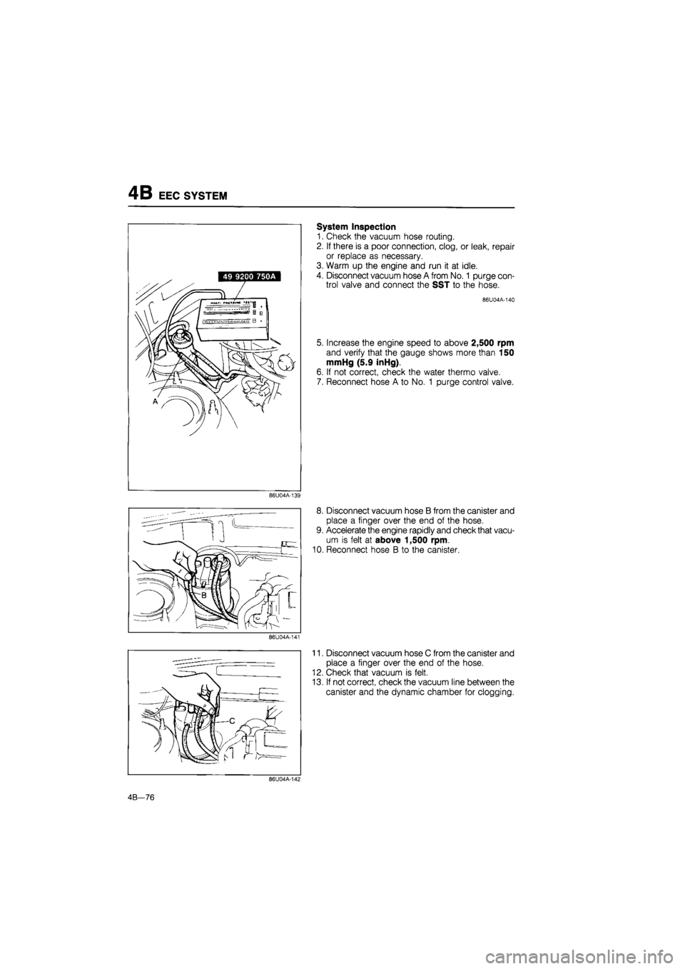
System Inspection
1. Check the vacuum hose routing.
2. If there is a poor connection, clog, or leak, repair
or replace as necessary.
3. Warm up the engine and run it at idle.
4. Disconnect vacuum hose A from No.
1
purge con-
trol valve and connect the SST to the hose.
86 U 04 A-140
5. Increase the engine speed to above 2,500 rpm
and verify that the gauge shows more than 150
mmHg (5.9 inHg).
6. If not correct, check the water thermo valve.
7. Reconnect hose A to No. 1 purge control valve.
8. Disconnect vacuum hose B from the canister and
place a finger over the end of the hose.
9. Accelerate the engine rapidly and check that vacu-
um is felt at above 1,500 rpm.
10. Reconnect hose B to the canister.
11. Disconnect vacuum hose C from the canister and
place a finger over the end of the hose.
12. Check that vacuum is felt.
13. If not correct, check the vacuum line between the
canister and the dynamic chamber for clogging.
86U04A-142
4B—76
Page 542 of 1865

4B PCV SYSTEM
POSITIVE CRANKCASE VENTILATION
(PCV)
SYSTEM
76G04B-106
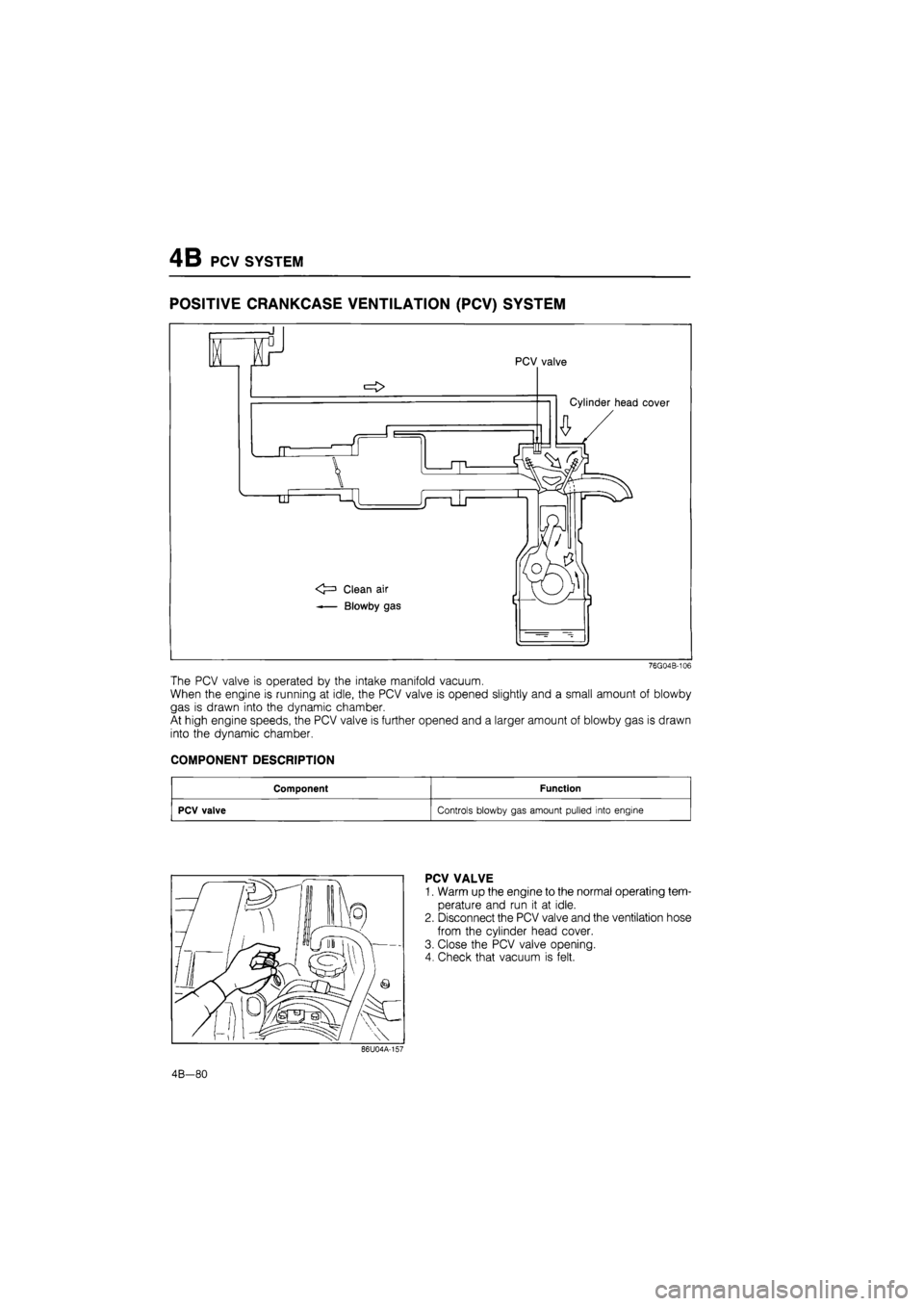
The PCV valve is operated by the intake manifold vacuum.
When the engine is running at idle, the PCV valve is opened slightly and a small amount of blowby
gas is drawn into the dynamic chamber.
At high engine speeds, the PCV valve is further opened and a larger amount of blowby gas is drawn
into the dynamic chamber.
COMPONENT DESCRIPTION
Component Function
PCV valve Controls blowby gas amount pulled into engine
PCV VALVE
1. Warm up the engine to the normal operating tem-
perature and run it at idle.
2. Disconnect the PCV valve and the ventilation hose
from the cylinder head cover.
3. Close the PCV valve opening.
4. Check that vacuum is felt.
4B—80
Page 545 of 1865

CONTROL SYSTEM 4B
CONTROL SYSTEM
Atmospheric
pressue sensor
Engine control unit
Brake light switch
Clutch switch
Circuti opening
relay
E/L control unit
Air flow meter
Neutral switch
76G04B-129
The control system consists of the input devices and the engine control unit. The engine control unit
controls the fuel injection amount (EGI), fuel injection pressure, bypass air amount, switch monitor func-
tion, and fail-safe function.
4B—83
Page 547 of 1865

CONTROL SYSTEM 4B
Output Devices and Engine Conditions
DC <
s UJ OC
Q. 3 O) c
CO
ffl <
> C o t: S CO
o x
03 "D > 16 O > -FC O O I O 0) .. .c CD
SB to ro
_Q
O O <
> c o t CO
o x
UJ O Z z ? ? ?5 n T (9 O oo: z r uj
c o o 31 c O 3 OC
o
I—
LU
> Q W0UJ> JW J
cc -J
-i -i
S5
Sxi-oo t >u-d
-<=
"O c y c « ir
co
aj
a ffl c o a c o o 0) 3 n> o n i_ > o CD
s <0^0
E 13 O tr C3 LU
->
o
111
E
UJ < o c "
UJ
3 o CD 13
o C CD
B ffl <° ro
"H
ui1
o cc _i o UJ C
o < rf OC 111
o <
o
Q UJ
£ OC <
£
o o
o (9 5 N ± UJ
| = 5o
I "O—_ ZqIIJ SjZ Z Oo < O z tt-UJ
r-D c o c ro ir
ro
a?
o be
T3 CD CO O o cc <3 UJ,
LL LL O
C o J5
o >
CD Q. CD O c o,
Q. 13 o O)
o
3 O) 03
03 3 cn cn CD Q. O
E 3 3 O ro
O
3 O
UJ
OC (3 LU
O
cn 0)
J5 CD Q. O 03 O) ro "So "O c CM
O
CO ro a >, _o
c 03 Q. O
3 O cr cd LU
T3 03 ro 03 a o o c CD o> ro tn "O c CM
o
c 03 a O
o CO CM
O o o
CD > o _o ro
fa _ffl O
CD >
O o LO LO 03 > o JD CO
Q. E 03
CD js: CO
c 03
c 03 CL O
| ro S <
CO
a
LL ° CM rri
$2 CM
CD
in
o §
O
s §
a£ E to
03 -S
CO •a 03 w o 03 £ iS >
"O •
03:
o ro
£ °
Q_ CD
"O
CD
J 3
Q_ CO
O
CO
ro 2
UJ 03
C > ffl ffl r ?
o c C
CD CD
5" o O
CO
(/> Z o
o o UJ z o z UJ
Oh
UJUJO
£ii
o
i- a
S5i
o
Ul cc
50
UJ >
< >
OC <
oc UJ O OC I-
in =J
UJ O
oc
UJ
o. oc
OC o UJ
UJ u OC 3 a.
a.
ui
ffl
a 3 I UJ
UJ
oo<
<0
z >
0
Q. 3 1 UJ
o
c/> . to Z HI < UJ > _ Q.
—J
—I
<
m
O O gc <
76G04B-109
4B-85
Page 549 of 1865

CONTROL SYSTEM 4B
ENGINE CONTROL UNIT
Engine Signal Monitor (49 9200 162) and Adapter (49 9200 163).
Adapter harness 49 9200 163
Engine wiring harnessN
Selector switch
Monitor switch
Engine control unit
terminal number
Terminals
(A and 8)
ENGINE SIGNAL MONITOR
86U04A-171
The Engine Signal Monitor (49 9200 162) was developed to check the control unit terminal voltages.
This monitor easily inspects the individual terminal voltages through selection of the monitor switch.
How to Use the Engine Signal Monitor
1. Connect the Engine Signal Monitor (49 9200 162) between the engine control unit and the en-
gine harness using the adapter (49 9200 163).
2. Turn the selector switch and monitor switch to select the terminal number.
3. Check the terminal voltage.
Caution
Never apply voltage to terminals A and B.
4B-87
Page 550 of 1865

4B CONTROL SYSTEM
Terminal Voltage
If the input and output devices and related wiring are normal, but the engine control unit terminal volt-
age is incorrect, replace the engine control unit.
Terminal Input Output Connection to Voltage (After warming-up) Remarks Terminal Input Output Connection to IGN: ON Idle Remarks
1A — — — — —
1B o Self-Diagnosis Checker (Code number)
For 3sec. after ignition switch OFF ->• ON: below 6.2V (Buzzer sounds) After 3sec.: Battery voltage (Buzzer does not sound)
• Using Self-Diagnosis Check-er and test con-nector grounded • Buzzer sounds: below 6.2V • Buzzer does not sound: Battery voltage
1C — — — — —
1D o Self-Diagnosis Checker (Monitor lamp)
Test connector grounded
For 3sec. after igni-tion switch OFF ON:
below 6.2V (light il-luminates) After 3sec.: Battery voltage (light does not illuminate)
(Test connector grounded) approx. 10V (Test connector not grounded) Monitor lamp ON: below 6.2V Monitor lamp OFF: Battery voltage
With Self-Diagnosis
Checker
1E O Idle switch Accelerator pedal released: below 1.5V
Accelerator pedal depressed: Battery voltage
1F o A/C relay A/C switch ON: below 2.5V A/C switch OFF: Battery voltage
Blower motor ON
1G — — — — —
1H o Water thermo switch Below 1,5V Radiator temp.:
above 17°C (63°F)
11 o Electrical load con-trol unit Electrical load ON: below 1.5V Electrical load OFF: Battery voltage Electrical load: Rear defroster Headlight Blower motor (3rd & 4th position) Electrical fan
1J o Brake light switch Brake pedal released: below 1.5V
Brake pedal depressed: battery voltage
1K — — — — — —
1L o A/C switch A/C switch ON: below 1.5V
A/C switch OFF: battery voltage
Blower motor: ON
1M o Ignition coil © terminal Battery voltage *1 Battery voltage *1 Engine Signal Monitor: green and red lights flash
1N — — — — —
10 — — — —
4B-88
Page 551 of 1865

CONTROL SYSTEM 4B
Terminal Input Output Connection to Voltage (After warming-up) Remarks Terminal Input Output Connection to IGN: ON Idle Remarks
1P — — — — —
1Q — — — — —
1R — — — — —
1S o Air bypass solenoid valve (Idle-up C) and P/S pressure switch
Battery voltage While solenoid ON (Refer to page 4B—35): below 1.5V
1T — — — — —
1U — — — — —
1V 0 MTX
Neutral and clutch switch
In-gear condition Clutch pedal depressed: battery voltage Clutch pedal released: below 1,5V
Neutral: constant battery voltage
1W O Test connector Test connector grounded: below 1,5V Test connector not grounded: battery voltage Green connector, 1-pin
1X — — — — —
2A o V ref 4.5—5.5V
2B 0 Air flow meter (Vc) 6-10V
2C — — Ground (E2) Approx. OV
2D o Oxygen sensor OV 0-1.OV • Cold engine: 0V at idle • After warming-up: Increase engine speed: 0.5—1.0V Deceleration: 0—0.4V
2E 0 Air flow meter (Vs) Approx. 1.7V Approx. 3—5V Increase engine speed:
voltage increases
2F — -— — —
2G 0 Throttle sensor Accelerator pedal released:
0.4—0.6 V
2H 0 Atmospheric pres-sure sensor At sea level: approx. 4.0V
21 0 Water thermo sensor 0.3—0.6 V Engine coolant temp. 20°C (68°F): approx. 2.5V
2J o Air flow meter (In-
take air thermo
sensor)
Approx. 2.3V at 20°C (68°F)
2K o Solenoid valve (Pres-
sure regulator
control)
For 120 sec. after ignition switch OFF - ON: below 1.5V
For 120 sec. after
starting: below 1.5V
Hot condition: Cool-ant temp, above 70°C (158°F) Intake air temp, above 10°C (50°F)
2K o Solenoid valve (Pres-
sure regulator
control)
Battery voltage Other conditions
2L — — — — —
2M — — —
4B-89
Page 552 of 1865

4B CONTROL SYSTEM
Terminal Input Output Connection to Voltage (After warming-up) Remarks Terminal Input Output Connection to IGN: ON Idle Remarks
2N o Solenoid valve (EGR) Below 1,5V • Cold engine: be-low 1,5V Radiator coolant temp.—below 17°C (63°F) or Engine coolant temp.—below 70°C (158°F)
• Engine above ap-prox. 1,500 rpm: Battery voltage
20 o Air bypass solenoid valve (Idle-up B) Battery voltage While solenoid ON (Refer to page 4B-35): below 1.5 V
2P o Solenoid valve
(Purge control valve)
Battery voltage • Medium and high
load: below 1,5V
2Q — — — —
2R — — Ground (E02) Below 1,5V
3A — — Ground (E01) Below 1.5V
3B O Ignition switch (Start position) Below 1,5V While cranking: bat-
tery voltage
3C o Injector (No. 4 and No. 2) Battery voltage *1 Battery voltage *1 Engine Signal Monitor green and red lights flash
3D o Inhibitor switch "N" or "P" range: below 2.0V
Other ranges: battery voltage
ATX
3E o Injector (No. 1 and No. 3) Battery voltage *
1
Battery voltage *1 Engine Signal Monitor: green and red lights flash
3F -— — — —
3G — Ground (Ei) Below 1.5V
3H — — — —
31 o — Ma ri relay Battery voltage
3J — — Battery Battery voltage For back-up
76G04B-110
31 3G 3E 3C 3A
3J 3H 3F 3D 3B
2Q 20 2M 2K 21 2G 2E 2C 2A
2R 2P 2N 2L 2J 2H 2F 2D 2B
1W 1U 1S 1Q 10 1M 1K 11 1G 1E 1C 1A
1X 1V 1T 1R 1P 1N 1L 1J 1H 1F 1D 1B
4B—90