MAZDA 626 1987 Workshop Manual
Manufacturer: MAZDA, Model Year: 1987,
Model line: 626,
Model: MAZDA 626 1987
Pages: 1865, PDF Size: 94.35 MB
MAZDA 626 1987 Workshop Manual
626 1987
MAZDA
MAZDA
https://www.carmanualsonline.info/img/28/57059/w960_57059-0.png
MAZDA 626 1987 Workshop Manual
Trending: ECO mode, gas type, wheel bolts, tire type, sunroof, power steering fluid, fuse
Page 691 of 1865
EXHAUST SYSTEM 4D
EXHAUST PIPE AND MAIN SILENCER
Removal and Installation
1. Remove in the sequence shown in the figure.
2. Install in the reverse order of removal.
3. Check for exhaust leakage.
64—89 N-m
37—52 N-m (3.8—5.3 m-kg, 27—38 ft-lb)
76G04D-045
1. Front exhaust pipe bracket 4. Silencer hanger
2. Front exhaust pipe 5. Middle pipe
3. Pre-silencer 6. Main silencer
4D—20
Page 692 of 1865
FUEL SYSTEM 4D
FUEL SYSTEM
STRUCTURAL VIEW
RF-CX
RF-N
76G04D-046
1. Fuel tank
2. Fuel filter
3. Fuel injection pump
4. Fuel injection nozzle
5. Sedimenter
4D—21
Page 693 of 1865
4D FUEL SYSTEM
76G04D-047
76G04D-048
76G04D-049
FUEL FILTER
On-Vehicle Inspection
Check for water in the fuel filter. If present drain the
water. (Refer to page 4D—4.)
Replacement
Removal
1. Disconnect the water level sensor connector (ECE).
2. Remove the water level sensor. (ECE).
3. Remove the fuel filter cartridge.
Warning
Keep fire and open flame away from the fuel
area.
Installation
1. Apply fuel to the O-ring of the fuel filter cartridge
and install it onto the filter body.
2. Install the water level sensor (ECE).
3. Connect the water level sensor connector (ECE).
4. Bleed air from fuel filter. (Refer to page 4D—4.)
5. Check for fuel leakage.
SEDIMENTER (GENERAL)
On-Vehicle Inspection
Check for water in the sedimenter. If present, drain
the water. (Refer to page 4D—4.)
4D—22
Page 694 of 1865
FUEL SYSTEM 4D
Replacement
1. Remove the sedimenter from the body.
2. Apply fuel to a new O-ring, and install it onto the
sedimenter body with water level sensor.
76G04D-051
WATER LEVEL SENSOR
Inspection
1. Remove the water level sensor.
(ECE)
Remove the water level sensor from the fuel filter.
(GENERAL)
Remove the water level sensor from the sedimenter
body.
76G04D-052
2. Check the water level sensor for continuity with an
ohmmeter. Replace if necessary.
ECE
Continuity : Pulled condition
No continuity: Pushed condition
76G04D-053
GENERAL
Continuity : Pushed condition
No continuity: Pulled condition
3. Apply fuel to a new O-ring and install it onto the
sensor.
4. Install the water level sensor to the fuel filter (ECE)
or the sedimenter (General).
5. Check for fuel leakage.
76G04D-054
4D-23
Page 695 of 1865
4D FUEL SYSTEM
INJECTION PUMP
On-Vehicle Inspection
Fuel cut solenoid valve
1. Run the engine at idle.
2. Disconnect the solenoid valve connector, and let
the engine stop.
3. If the engine does not stop, replace the fuel cut
solenoid valve.
76G04D-055
Pick up coil
1. Disconnect the pick up coil connector.
2. Check for continuity of the coil using an ohmmeter.
3. Replace it if there is not continuity.
76G04D-056
O
o
>=
=<
t= —i V
' 1 -4
n
5-
U
o
1 mm (0.39 in) Injection Timing Adjustment
Inspection
Check the injection timing. (Refer to page 4D—5.)
Injection timing
RF-CX: ATDC 10
RF-N : TDC 0°
76G04D-057
Adjustment
1. Loosen the injection pump mounting nut.
2. Loosen the injection pump bracket bolt.
76G04D-058
4D—24
Page 696 of 1865
FUEL SYSTEM 4D
RF-CX
o
M
o
10-
RF-N
M
m
M
o TO"
5-
76G04D-059
76G04D-060
76G04D-061
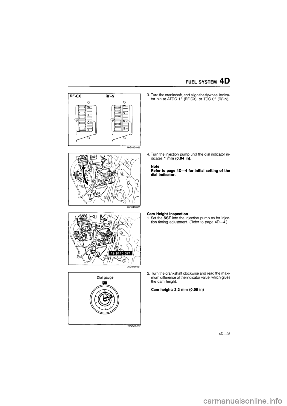
3. Turn the crankshaft, and align the flywheel indica-
tor pin at ATDC 10 (RF-CX), or TDC 0° (RF-N).
4. Turn the injection pump until the dial indicator in-
dicates 1 mm (0.04 in).
Note
Refer to page 4D—4 for initial setting of the
dial indicator.
Cam Height Inspection
1. Set the SST into the injection pump as for injec-
tion timing adjustment. (Refer to page 4D—4.)
2. Turn the crankshaft clockwise and read the maxi-
mum difference of the indicator value, which gives
the cam height.
Cam height: 2.2 mm (0.08 in)
76G04D-062
4D—25
Page 697 of 1865
4D FUEL SYSTEM
Removal and Installation
1. Remove in the sequence shown in the figure, referring to the removal note for specially marked parts.
2. Install in the reverse order of removal.
59—69 N-m
(6.0—7.0 m-kg, 43-51 ft-lb)
19—26
N m
(1.9—2.6
m-kg,
14—19 ft-lb) 25—29
N-m .5—3.0 m-kg, 18—22
ft-lb)
19—26 N-m
(1.9—2.6
m-kg,
14—19 ft-lb)
76G04D-063
1. Accelerator cable
2. Injection pipe
3. Fuel hose
4. Water hose
5. Fuel cut solenoid valve con-
nector
6. Pick-up coil connector
7. Boost air hose (RF-CX)
8. Injection pump pulley lock
nut
9. Injection pump
Removal note
Injection pipe
Warning
a) Catch leaking fuel with a rag when remov-
ing the injection pipes.
b) Keep fire and open flame away from the fuel
area.
Remove the injection pipes.
76G04D-064
4D—26
Page 698 of 1865
FUEL SYSTEM 4D
76G04D-065
76G04D-066
Injection pump pulley
1. Put two 35—40 mm (1.3—1.6 in) long bolts through
the injection pump pulley and affix them in the
threaded holes of the injection pump bracket.
2. Loosen the injection pump pulley bolt.
3. Separate the injection pump pulley from the injec-
tion pump shaft with the SST.
Steps after installation
1. After installation adjust the injection timing. (Refer
to page 4D—24.)
2. Bleed air from the fuel line.
3. Check for fuel leakage.
76G04D-067
4D—27
Page 699 of 1865
4D FUEL SYSTEM
Overhaul
Service point
1. For overhauling the injection pump, see the "Repair Service and Maintenance" manual prepared
by the manufacturer of the pump.
2. If the inside of the injection pump is disassembled for maintenance, be sure to properly use the
checking device such as the pump tester.
76G04D-068
Manufacturer of Injection Pump:
Diesel Kiki Co., Ltd.
63G04D-312
Construction of VE Injection Pump
Servo diaphragm
Boost compensation stopper
p^ ^-Fue! cut solenoid
valve
'Cold start device
63G04D-313
4D—28
Page 700 of 1865

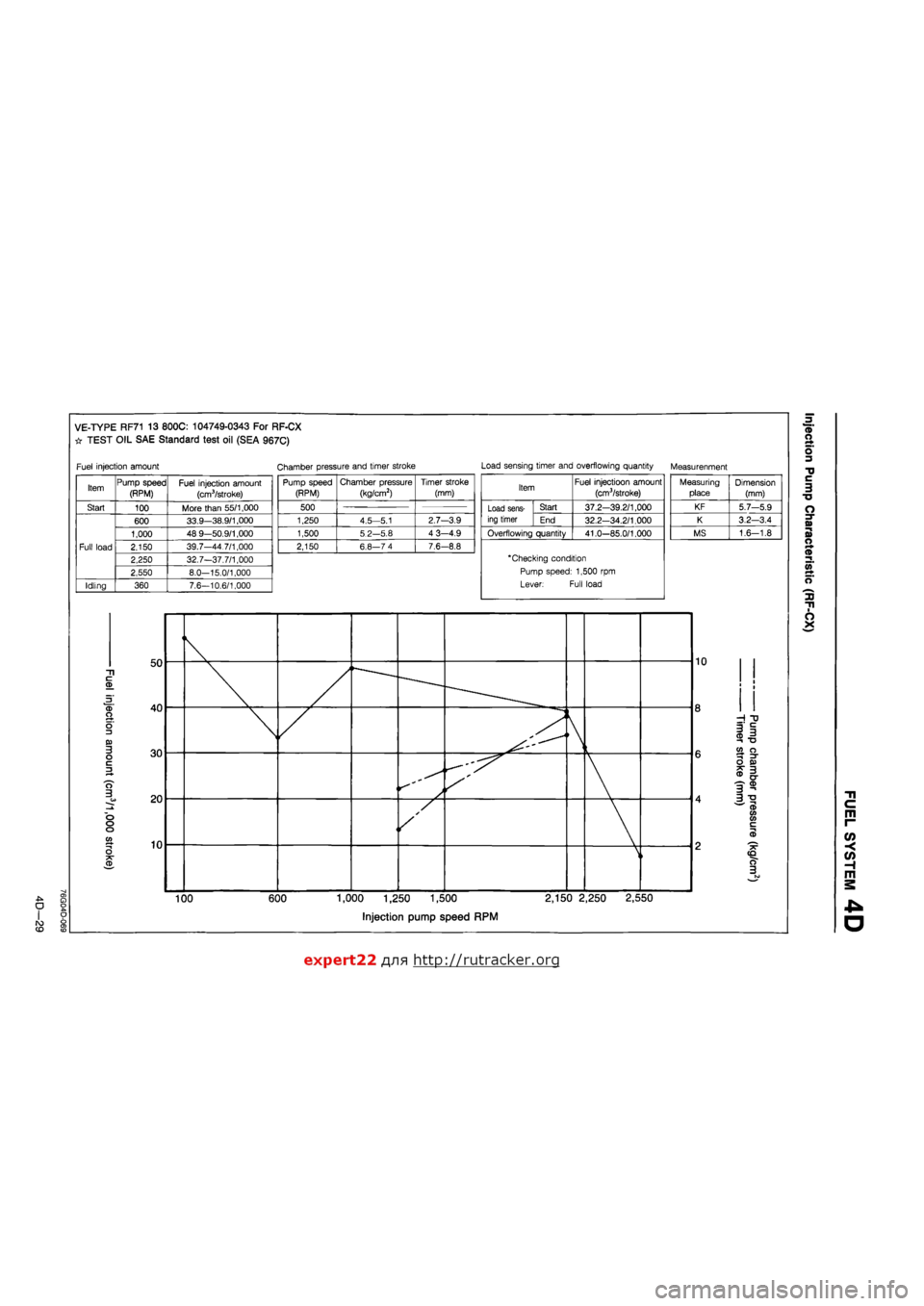
VE-TYPE RF71 13 800C: 104749-0343 For RF-CX
# TEST OIL SAE Standard test oil (SEA 967C)
Fuel injection amount Chamber pressure and timer stroke Load sensing timer and overflowing quantity Measurenment
Item Pump speed (RPM) Fuel injection amount
(cm3/stroke)
Start 100 More than 55/1,000
Full load
600 33.9—38.9/1,000
Full load
1,000 48 9—50.9/1,000
Full load 2,150 39.7—44 7/1,000 Full load
2,250 32.7-37.7/1,000
Full load
2,550 8.0—15.0/1,000
Idling 360 7.6—10.6/1,000
c CD
CD O
o 3 03 3 o c 3
O 3
o o o
o
CD
O
CD
50
40
30
20
10
Pump speed (RPM) Chamber pressure
(kg/cm2)
Timer stroke (mm)
500 500
1,250 4.5—5.1 2.7—3.9
1,500 5.2—5.8 4 3-4.9
2,150 6.8—7 4 7.6-8.8
Item Fuel injectioon amount
(cm3/stroke)
Load sens-ing timer
Start 37.2-39.2/1,000 Load sens-ing timer End 32.2-34.2/1.000
Overflowing quantity 41.0—85.0/1.000
"Checking condition
Pump speed: 1,500 rpm
Lever: Full load
Measuring place Dimension (mm)
KF 5.7—5.9
K 3.2—3.4
MS 1.6-1.8
/ J*
—
s
100 600 1,000 1,250 1,500
Injection pump speed RPM
10
2,150 2,250 2,550
CD
-I "0
i| T3 co o ^ =T O 03 3 cr
3? 3 ^ CD V) CO c CD
CD O r+ o 3
•D C 3 TJ
o
n> -i a> o r* ®
a> ^
o
3) n
O X
m r-
o> -<
(/> H m
D
expert22 ajia http://rutracker.org
Trending: clock setting, mirror, spare tire, differential, wheel bolt torque, inflation pressure, run flat


