MAZDA MX-5 1994 Workshop Manual
Manufacturer: MAZDA, Model Year: 1994, Model line: MX-5, Model: MAZDA MX-5 1994Pages: 1708, PDF Size: 82.34 MB
Page 1091 of 1708

AIR CONDITIONER u "C "F 26 24 22 20 18 16 14 12 10 40 59 60 70 RELATIVE HUMIDITY I ltem I Symptom 10. Read the dry thermometer at the air outlet, and calculate the difference between the inlet dry bulb and outlet dry bulb temperatures. 11. Verify that the intersection of the relative humidity and temperature difference is in the shaded zone. Checking Refrigerant Charge 1. Run the engine at a fast idle. 2. Operate the air conditioner at maximum cooling for a few minutes. 3. Determine the amount of refrigerant as shown below by observing the sight glass. 1 Bubbles present in sight glass 2 No bubbles present in sight glass Immediately after air conditioner turned OFF, refrigerant in sight glass stavs clear 141 When air conditioner turned OFF, re- frigerant foams, and then sight glass becomes clear -- Amount of refrigerant Insufficient refrigerant Action Check refrigerant pressure -- Too much or proper amount of refrig- erant Too much refrigerant Checking Refrigerant Pressure 1. Connect the manifold gauge set. (Refer to page U-25.) 2. Operate the engine at 1,500 rpm and set the air condi- tioner to maximum cooling. 3. Measure the low- and high-pressure sides. Turn air conditioner OFF, and watch bubbles (Refer to Items 3 and 4) Check refrigerant pressure Proper amount of refrigerant Stabilized condition Low-pressure side: 0.15-4.24 MPa {I .5--2.5 kgf/cm2, 22-35 psi) High-pressure side: 1.38-1.56 MPa (1 4.61 6.0 kgflcm*, 200-227 psi) Refrigerant amount normal Gartner Banana
Page 1092 of 1708
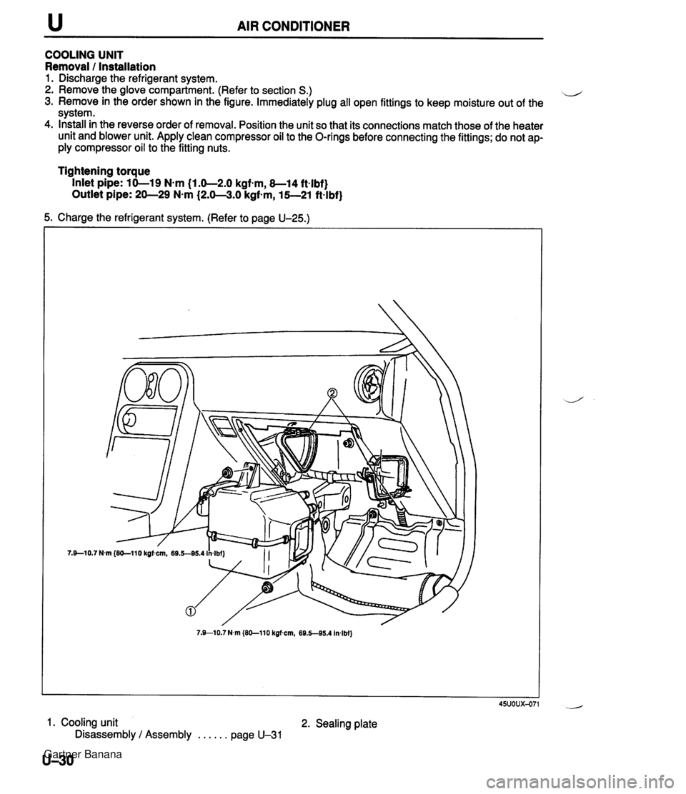
u AIR CONDITIONER COOLING UNIT Removal 1 Installation 1. Discharge the refrigerant system. 2. Remove the glove compartment. (Refer to section S.) il 3. Remove in the order shown in the figure. Immediately plug all open fittings to keep moisture out of the system. 4. Install in the reverse order of removal. Position the unit so that its connections match those of the heater unit and blower unit. Apply clean compressor oil to the O-rings before connecting the fittings; do not ap- ply compressor oil to the fitting nuts. Tightening torque Inlet pipe: 10-19 N-m (1.0-2.0 kgfsm, 8-14 ft-lbf} Outlet pipe: 20-29 N-m (2.0-3.0 kgf-m, 15--21 ft-lbf} 5. Charge the refrigerant system. (Refer to page U-25.) 7.910.7 N.m {EO-110 kgfmn, 69.5-95.4 In4bf} 45uoux-071 1. Cooling unit 2. Sealing plate Disassembly / Assembly . . . . . . page U-31 U-30 Gartner Banana
Page 1093 of 1708
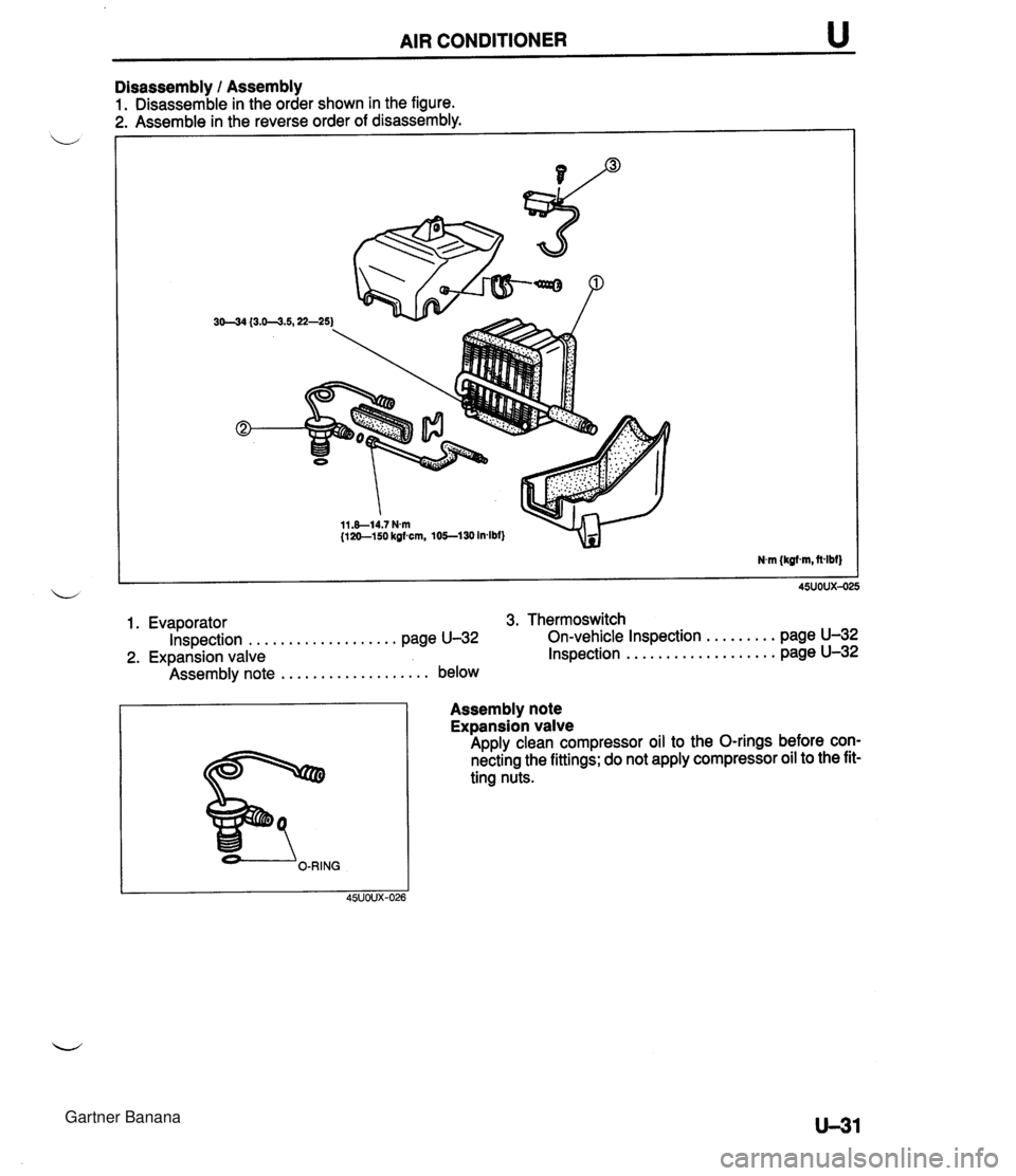
AIR CONDITIONER u Disassembly 1 Assembly 1. Disassemble in the order shown in the figure. 1. Evaporator 3. Thermoswitch ................... ......... Inspection page U-32 On-vehicle Inspection page U-32 ................... 2. Expansion valve Inspection page U-32 ................... Assembly note below Assembly note Expansion valve Apply clean compressor oil to the O-rings before con- necting the fittings; do not apply compressor oil to the fit- ting nuts. Gartner Banana
Page 1094 of 1708
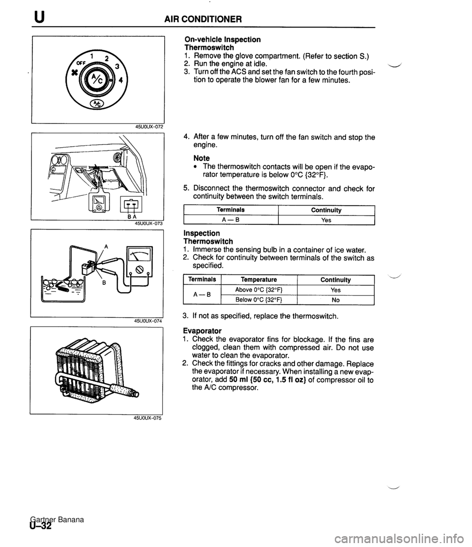
AIR CONDITIONER On-vehicle Inspection Thermoswitch 1. Remove the glove compartment. (Refer to section S.) 2. Run the engine at idle. u 3. Turn off the ACS and set the fan switch to the fourth posi- tion to operate the blower fan for a few minutes. 4. After a few minutes, turn off the fan switch and stop the engine. Note The thermoswitch contacts will be open if the evapo- rator temperature is below 0°C (32°F). 5. Disconnect the thermoswitch connector and check for continuity between the switch terminals. I Terminals I Continuity I I A-B I Yes I - -- Inspection Thermoswitch 1. Immerse the sensing bulb in a container of ice water. 2. Check for continuity between terminals of the switch as specified. 3. If not as specified, replace the thermoswitch. Continuity ( Terminals I Temperature A-B Evaporator 1. Check the evaporator fins for blockage. If the fins are clogged, clean them with compressed air. Do not use water to clean the evaporator. 2. Check the fittings for cracks and other damage. Replace the evaporator if necessary. When installing a new evap- orator, add 50 ml (50 cc, 1.5 fl oz) of compressor oil to the A/C compressor. d Above 0°C {32OFj Below 0°C (32°F) Yes No Gartner Banana
Page 1095 of 1708
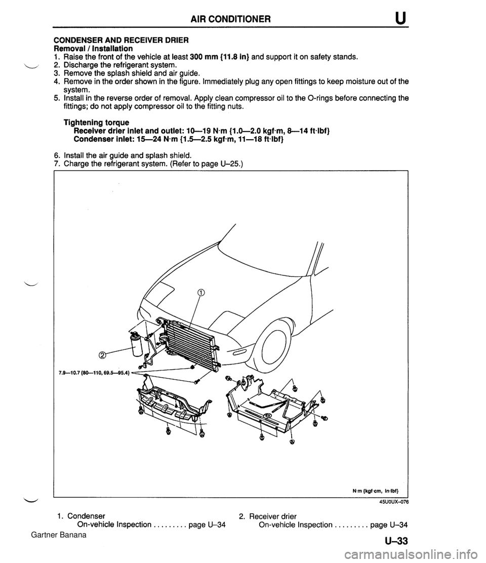
AIR CONDITIONER u CONDENSER AND RECEIVER DRIER Removal 1 Installation 1. Raise the front of the vehicle at least 300 mm (11.8 in) and support it on safety stands. 2. Discharge the refrigerant system. 3. Remove the splash shield and air guide. 4. Remove in the order shown in the figure. Immediately plug any open fittings to keep moisture out of the system. 5. Install in the reverse order of removal. Apply clean compressor oil to the O-rings before connecting the - fittings; do not apply compressor oil to the fitting nuts. Tightening torque Receiver drier inlet and outlet: 10-19 N-m (1.0-2.0 kgf-m, 8-14 ft-lbf) Condenser inlet: 15-24 N.m (1.5-2.5 kgfsm, 11-18 ft-lbf} 6. Install the air guide and splash shield. 7. Charge the refrigerant system. (Refer to page U-25.) 1. Condenser 2. Receiver drier On-vehicle Inspection . . . . . . . . . page U-34 On-vehicle Inspection . . . . . . . . . page U-34 U-33 Gartner Banana
Page 1096 of 1708
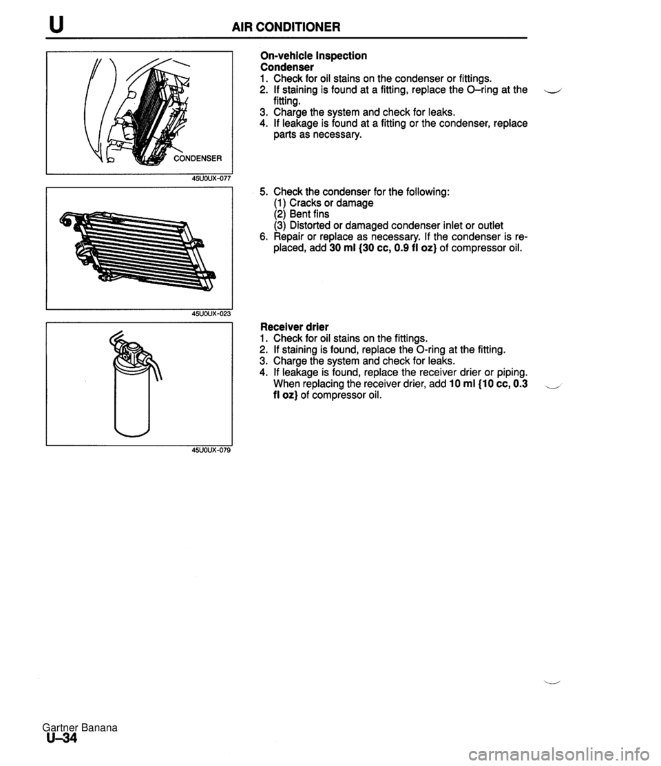
u AIR CONDITIONER On-vehicle Inspection Condenser 1. Check for oil stains on the condenser or fittings. 2. If staining is found at a fitting, replace the O-ring at the u fitting. 3. Charge the system and check for leaks. 4. If leakage is found at a fitting or the condenser, replace parts as necessary. 5. Check the condenser for the following: (1) Cracks or damage (2) Bent fins (3) Distorted or damaged condenser inlet or outlet 6. Repair or replace as necessary. If the condenser is re- placed, add 30 ml(30 cc, 0.9 fi oz} of compressor oil. Receiver drier 1. Check for oil stains on the fittings. 2. If staining is found, replace the O-ring at the fitting. 3. Charge the system and check for leaks. 4. If leakage is found, replace the receiver drier or piping. When replacing the receiver drier, add 10 ml I10 cc, 0.3 -, fl or) of compressor oil. Gartner Banana
Page 1097 of 1708
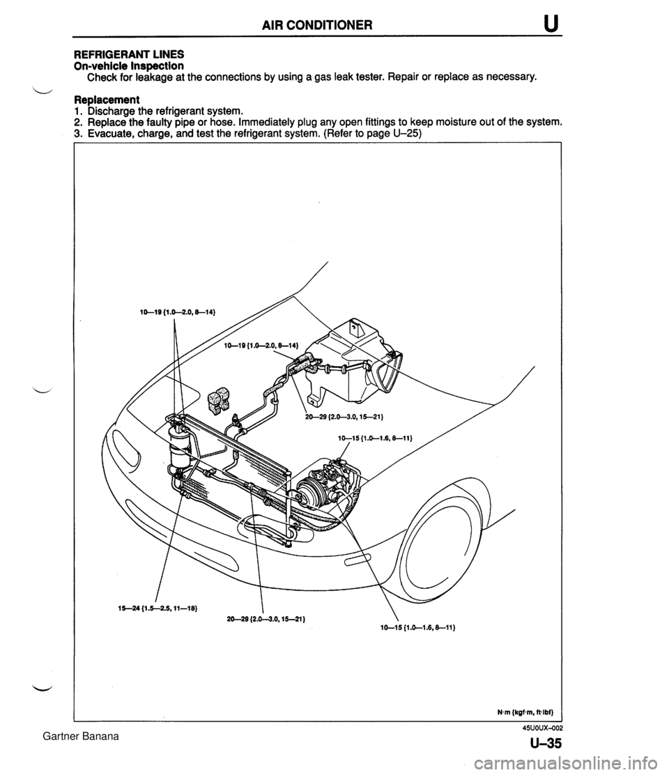
AIR CONDITIONER u REFRIGERANT LINES On-vehicle Inspection Check for leakage at the connections by using a gas leak tester. Repair or replace as necessary. b Replacement 1. Discharge the refrigerant system. 2. Replace the faulty pipe or hose. Immediately plug any open fittings to keep moisture out of the system. 3. Evacuate, charge, and test the refrigerant system. (Refer to page U-25) N.m (kgf m, fvlbf) Gartner Banana
Page 1098 of 1708

u AIR CONDITIONER CONDENSER FAN Removal / Installation 1. Disconnect the negative battery cable. 2. Disconnect the cooling fan and condenser fan connector. 3. Remove the bolts. 4. Remove in the order shown in the figure. 5. Install in the reverse order of removal. 1. Cooling fan 2. Condenser fan Inspection 1. Disconnect the condenser fan connector. 2. Verify that the condenser fan motor runs when connect- ing battery positive voltage to terminal A and grounding terminal B. B+: Battery positive voltage u 45UOUX-082 U-36 Motor operation Yes Connection B+ A GND B Gartner Banana
Page 1099 of 1708
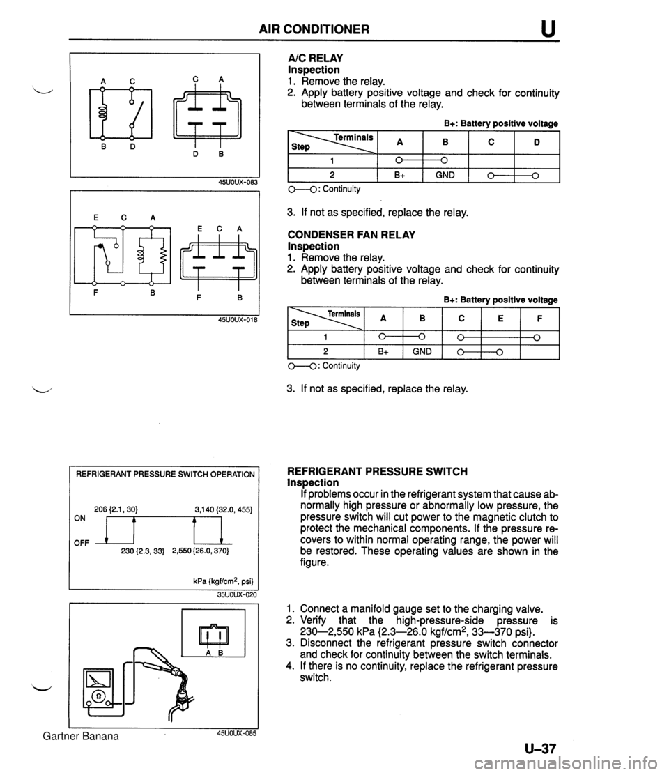
AIR CONDITIONER REFRIGERANT PRESSURE SWITCH OPERATION 206 {2.1,30) 3,140 (32.0, 455) OFF ON n 230 {2.3,33) 2,550 (26.0,370) A/C RELAY Inspection 1. Remove the relay. 2. Apply battery positive voltage and check for continuity between terminals of the relay. B+: Battery positive voltage 3. If not as specified, replace the relay. CONDENSER FAN RELAY lnspection 1. Remove the relay. 2. Apply battery positive voltage and check for continuity between terminals of the relay. B+: Battery positive voltage 1 2 O--(): Continuity 3. If not as specified, replace the relay. 0 B+ 1 2 REFRIGERANT PRESSURE SWITCH lnspection If problems occur in the refrigerant system that cause ab- normally high pressure or abnormally low pressure, the pressure switch will cut power to the magnetic clutch to protect the mechanical components. If the pressure re- covers to within normal operating range, the power will be restored. These operating values are shown in the figure. kPa (kgf/cm2, psi) 35UOUX-020 1. Connect a manifold gauge set to the charging valve. 2. Verify that the high-pressure-side pressure is 230-2,550 kPa (2.3-26.0 kgf/cm2, 33-370 psi). 3. Disconnect the refrigerant pressure switch connector and check for continuity between the switch terminals. 4. If there is no continuity, replace the refrigerant pressure switch. 45UOUX-085 0 GND 0 B+ 0 0 GND 0 0 0 0 3 Gartner Banana
Page 1100 of 1708
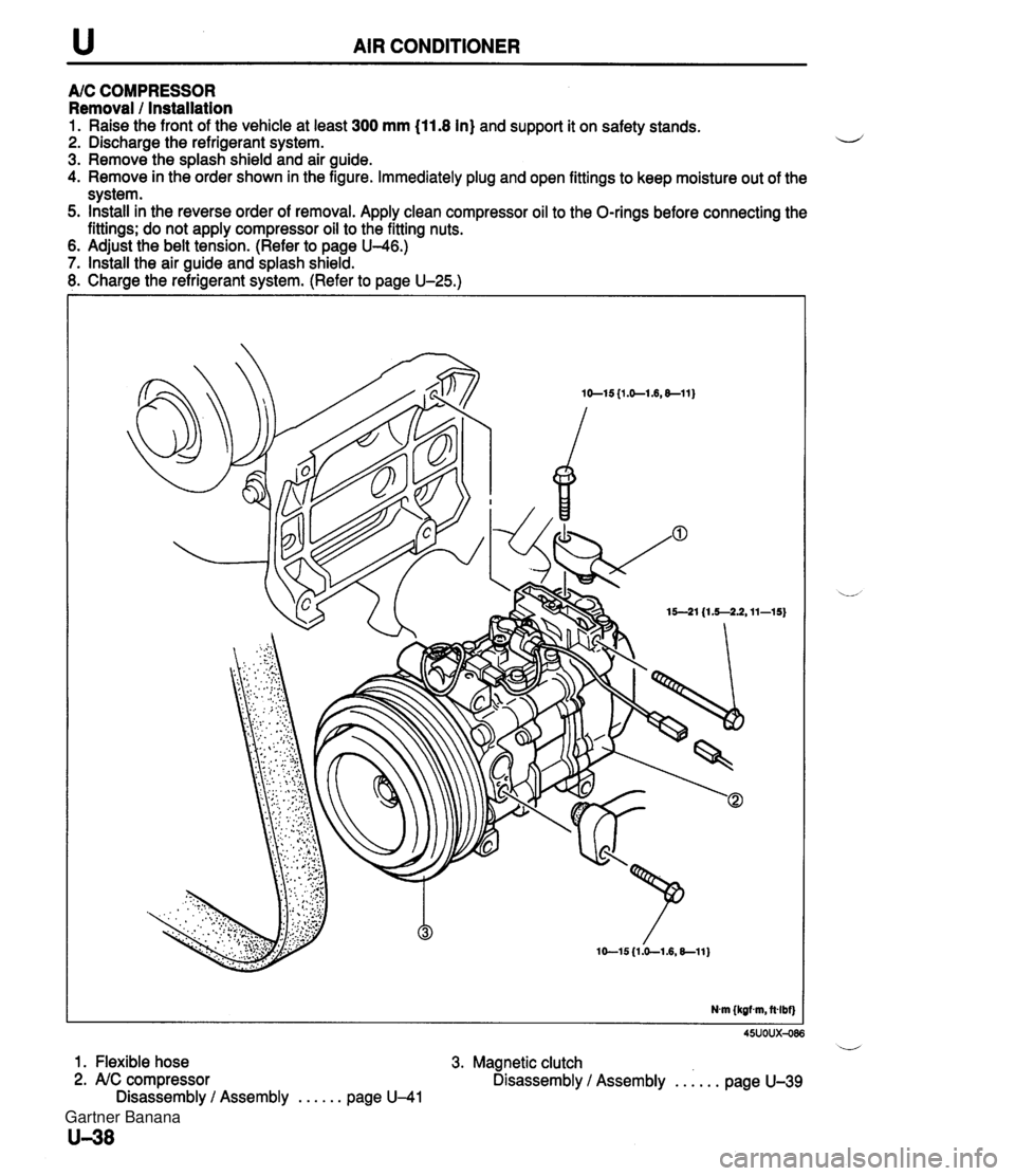
u AIR CONDITIONER A/C COMPRESSOR Removal / Installation 1. Raise the front of the vehicle at least 300 mm (11.8 In) and support it on safety stands. 2. Discharge the refrigerant system. i~ 3. Remove the splash shield and air guide. 4. Remove in the order shown in the figure. Immediately plug and open fittings to keep moisture out of the system. 5. Install in the reverse order of removal. Apply clean compressor oil to the O-rings before connecting the fittings; do not apply compressor oil to the fitting nuts. . 6. Adjust the belt tension. (Refer to page U-46.) 7. Install the air guide and splash shield. 8. Charge the refrigerant system. (Refer to page U-25.) 45uoux-086 i/ 1. Flexible hose 3. Magnetic clutch 2. AIC compressor Disassembly / Assembly . . . . . . page U-39 Disassembly / Assembly . . . . . . page U-41 Gartner Banana