MAZDA MX-5 1994 Workshop Manual
Manufacturer: MAZDA, Model Year: 1994,
Model line: MX-5,
Model: MAZDA MX-5 1994
Pages: 1708, PDF Size: 82.34 MB
MAZDA MX-5 1994 Workshop Manual
MX-5 1994
MAZDA
MAZDA
https://www.carmanualsonline.info/img/28/57072/w960_57072-0.png
MAZDA MX-5 1994 Workshop Manual
Trending: alternator belt, technical data, heater, coolant capacity, warning light, instrument cluster, battery capacity
Page 1281 of 1708
CONSTRUCTION @ I Trunk lid I @ I Splash protector No. @I I Rear deck member Part Name @ @ I @ I Light housing No. Rear end panel Rear deck panel @ I Floor center pan Part Name @ I @ / Rear fender panel @ @I @ I Crossmember No. 3 Seal plate Quarter panel Floor side panel I @ I Rear fender, lower @ Fuel filler lid @ @ 1 Floor side plate I I I I @ 1 Side sill B, inner Crossmember No. 4 Tank floor pan assy @ @ 1 Bumper bracket @ @ Trunk floor assy @ @ I Q / Front header, upper Door body Side sill, outer @ Floor side panel Rear side frame -1 .............. Both side rust-proof treated steel .............. One side rust-proof treated steel (Reverse side only) Side sill reinforcement Striker reinforcement Side sill C, inner @ @ 0 @ Side panel, inner Wheel inner house Beltline reinforcement Corner junction @ @ @ Side sill A, inner Hinge pillar, outer Cowl side panel Gartner Banana
Page 1282 of 1708
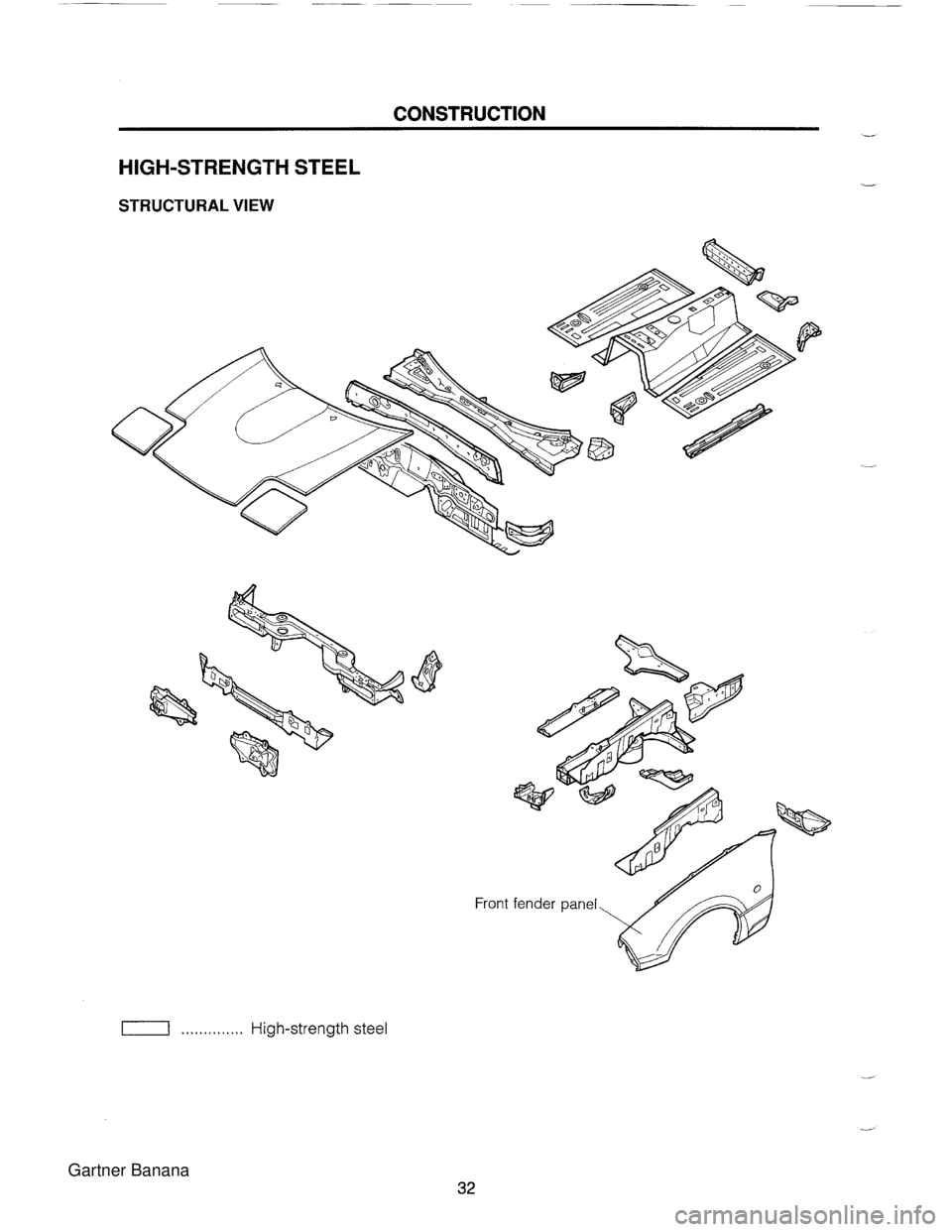
CONSTRUCTION HIGH-STRENGTH STEEL STRUCTURAL VIEW Front TI .............. High-strength steel Gartner Banana
Page 1283 of 1708
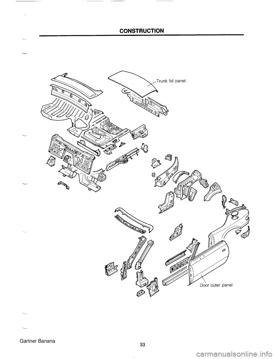
CONSTRUCTION . Gartner Banana
Page 1284 of 1708
Page 1285 of 1708
PANEL REPLACEMENT CROSSMEMBER (NO. 1) ............................................. 36 SHROUD PANEL ASSY ............................................... 38 WHEEL APRON PANEL ............................................... 40 WHEEL APRON PANEL ASSY .................................... 42 COWL SIDE PANEL ...................................................... 44 SIDE SILL PANEL ASSY .............................................. 46 FRONT PILLAR, OUTER COWL SlDE PANEL, HINGE PILLAR, INNER COWL SlDE PANEL AND SIDE SILL PANEL ............................................ 48 REAR FENDER PANEL ................................................ 52 REAR END PANEL ....................................................... 54 TRUNK FLOOR PAN, FLOOR SIDE PANEL .............. 56 Gartner Banana
Page 1286 of 1708
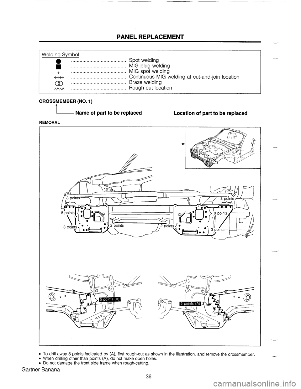
PANEL REPLACEMENT Welding Symbol ....................................... Spot welding ................................... .... MIG plug welding ..................................... 4- MIG spot welding ti.&+ ....................................... continuous MIG welding at cut-and-join location ....................................... Braze welding ....................................... Rough cut location CROSSMEMBER (NO. 1) 1 Name of part to be replaced Location of part to be replaced I REMOVAL I To drill away 8 points indicated by (A), first rough-cut as shown in the illustration, and remove the crossmember. When drilling other than points (A), do not make open holes. Do not damage the front side frame when rough-cutting. Gartner Banana
Page 1287 of 1708
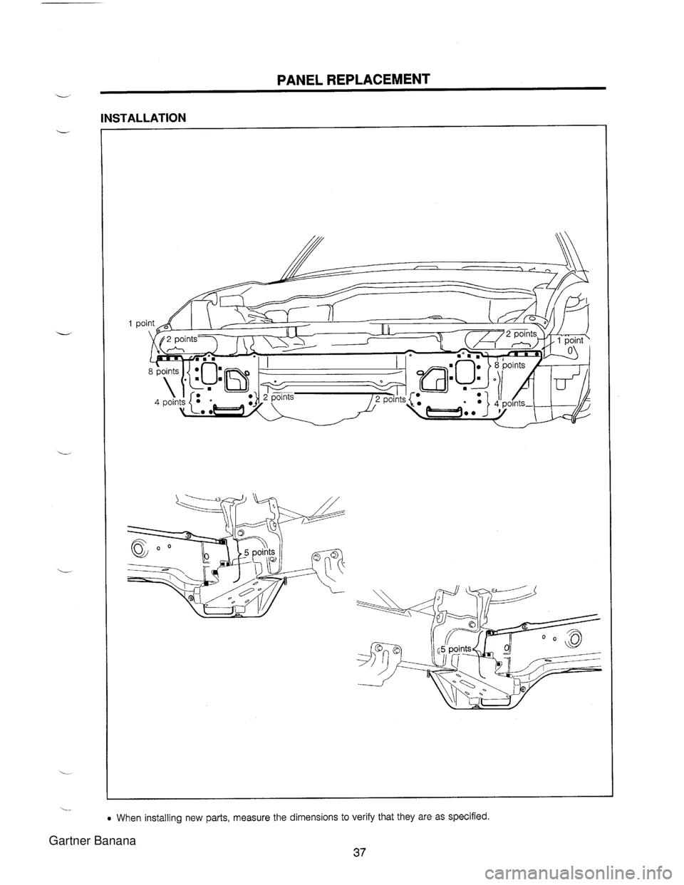
L PANEL REPLACEMENT INSTALLATION 0 When installing new parts, measure the dimensions to verify that they are as specified. 37 Gartner Banana
Page 1288 of 1708
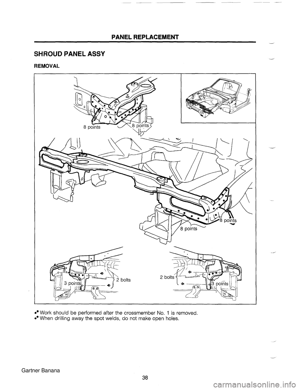
PANEL REPLACEMENT - SHROUD PANEL ASSY REMOVAL Work should be performed after the crossmember No. 1 is removed. When drilling away the spot welds, do not make open holes. Gartner Banana
Page 1289 of 1708
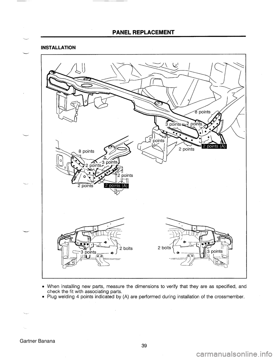
PANEL REPLACEMENT - INSTALLATION When installing new parts, measure the dimensions to verify that they are as specified, and check the fit with associating parts. Plug welding 4 points indicated by (A) are performed during installation of the crossmember. Gartner Banana
Page 1290 of 1708
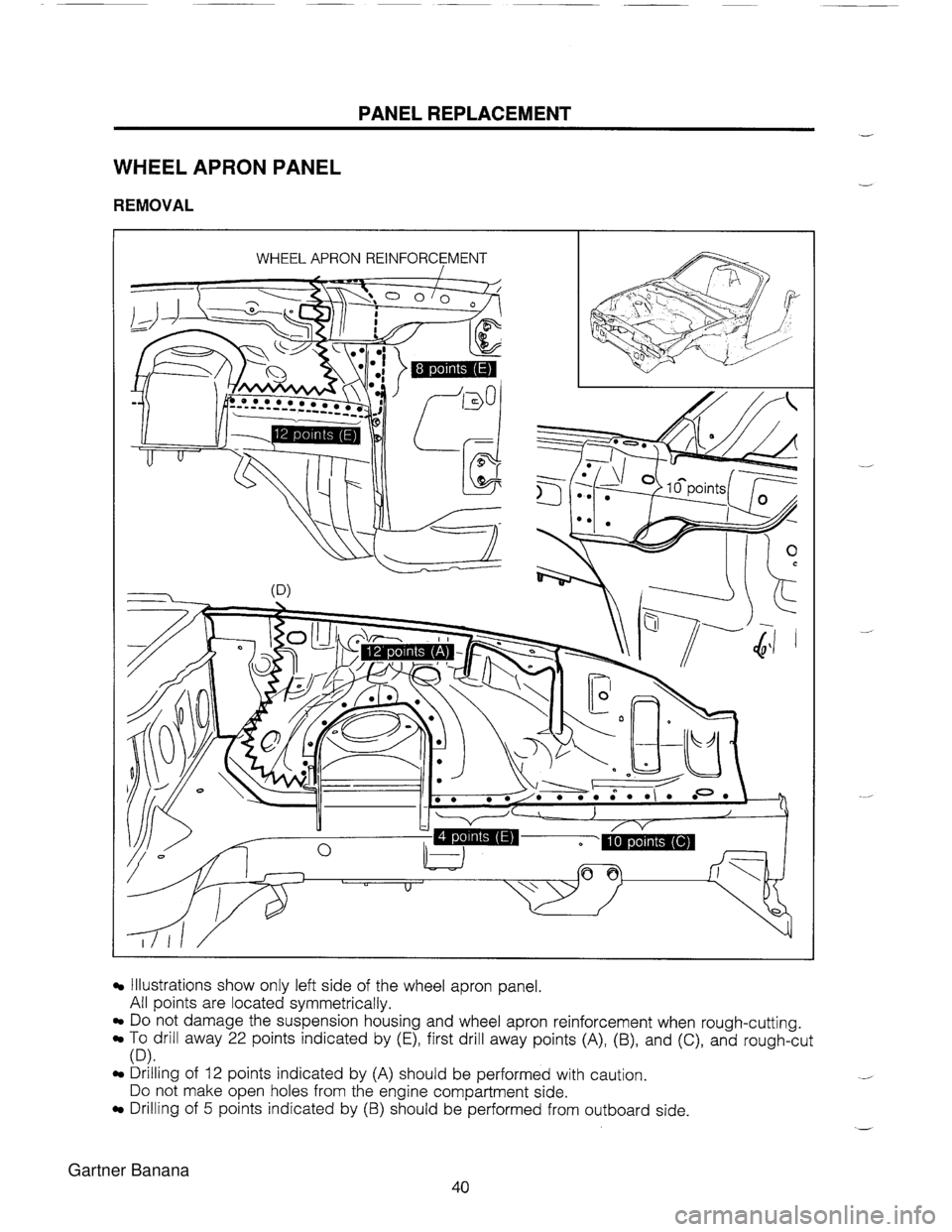
PANEL REPLACEMENT WHEEL APRON PANEL REMOVAL WHEEL APRON REINFORCEMENT Illustrations show onlv left side of the wheel amon a an el All points are located symmetricallv. ~o.not damage the suspension housing and wheel apron reinforcement when rough-cutting. To drill away 22 points indicated by (E), first drill away points (A), (B), and (C), and rough-cut (D). Drilling of 12 points indicated by (A) should be performed with caution. Do not make open holes from the engine compartment side. Drilling of 5 points indicated by (B) should be performed from outboard side. Gartner Banana
Trending: rear view mirror, height, tires, high beam, jump start, clock setting, transmission fluid

