lock MAZDA MX-5 1994 Repair Manual
[x] Cancel search | Manufacturer: MAZDA, Model Year: 1994, Model line: MX-5, Model: MAZDA MX-5 1994Pages: 1708, PDF Size: 82.34 MB
Page 302 of 1708

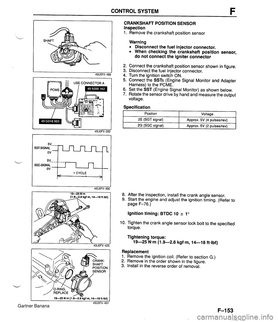
CONTROL SYSTEM 1 1 USE CONNECTOR A CRANKSHAFT POSITION SENSOR Inspection 1. Remove the crankshaft position sensor 5v- - - - SGGSIGNAL ov Warning Disconnect the fuel injector connector. When checking the crankshaft position sensor, do not connect the igniter connector - - - - I 1 CYCLE < > 2. Connect the crankshaft position sensor shown in figure. 3. Disconnect the fuel injector connector. 4. Turn the ignition switch ON. 5. Connect the SSTs (Engine Signal Monitor and Adapter Harness) to the PCME. 6. Set the SST (Engine Signal Monitor) as shown below. 7. Rotate the sensor drive by hand and measure the output voltage. Specification I 1 - Position - ~oltaael 8. After the inspection, install the crank angle sensor. 9. Start the engine and adjust the ignition timing. (Refer to page F-76.) 2E (SGT signal) 2G (SGC signal) Ignition timing: BTDC 10 2 1" Approx. 5V (4 pulseslrev) Approx. 5V (2 pulseslrev) 10. Tighten the crank angle sensor lock bolt to the specified torque. Tightening torque: 19-25 N-m (1 .+2.6 kgfem, 14-1 8 ftelbf} Replacement 1. Remove the ignition coil. (Refer to section G.) 2. Remove in the order shown in the figure. 3. Install in the reverse order of removal. Gartner Banana
Page 306 of 1708

CONTROL SYSTEM LOCK 4. If not as specified, replace the main relay. MAIN RELAY lnspection 1. Verify that the main relay clicks when turning the ignition switch OFF -+ ON. 2. Apply battery positive voltage to terminal A and ground terminal B of the main relay. 3. Use an ohmmeter to check continuity of the terminals as shown. CLUTCH SWITCH Inspection 1. Disconnect the clutch switch connector. 2. Connect an ohmmeter to the switch. 3. Check continuity of the switch. Battery positive voltage applied - Continuity - Terminals CD L 4. If not as specified, replace the clutch switch. Battery positive voltage not applied No continuity Pedal Depressed Released Replacement 1. Disconnect the clutch switch connector. 2. Loosen the locknut. 3. Remove the clutch switch. 4. Install in the reverse order of removal. 5. Adjust the pedal height. (Refer to Section H.) Continuity Yes No 4. If not as specified, replace the neutral switch. NEUTRAL SWITCH lnspection 1. Disconnect the neutral switch connector. 2. Connect an ohmmeter to the switch. 3. Check continuity of the switch. Transmission Neutral Other ranges Continuity , Yes No Gartner Banana
Page 308 of 1708

Before beginning any service procedure. refer to section T of this manual for air bag system service warnings and audio antitheft system alarm conditions . ENGINE ELECTRICAL SYSTEM INDEX ....................................... G- 2 OUTLINE ..................................... G- 3 SPECIFICATIONS ........................... G- 3 TROUBLESHOOTING GUIDE .................. G- 4 CHARGING SYSTEM .......................... G- 6 PREPARATION ............................. G- 6 CIRCUIT DIAGRAM ......................... G- 6 TROUBLESHOOTING ....................... G- 7 BATTERY .................................. G- 8 ALTERNATOR .............................. G-10 DRIVE BELT ................................ G-13 IGNITION SYSTEM ............................ G-15 PREPARATION ............................. G-15 CIRCUIT DIAGRAM ......................... G-15 TROUBLESHOOTING ....................... G-16 IGNITION TIMING ........................... G-17 SPARK PLUG ............................... G-18 IGNITION COIL ............................. G-19 IGNITER ................................... G-19 HIGH-TENSION LEAD ....................... G-20 STARTING SYSTEM ........................... G-21 CIRCUIT DIAGRAM ......................... G-21 TROUBLESHOOTING ....................... G-21 STARTER .................................. G-22 STARTER INTERLOCK SWITCH (MT) ......... G-28 45UOGX401 Gartner Banana
Page 309 of 1708

G INDEX INDEX 1. Battery lnspection . . . . . . . . . . . . . . . . . page G- 8 Recharging . . . . . . . . . . . . . . . . page G- 9 Replacement . . . . . . . . . . . . . . page G-10 2. Alternator Removal / lnstallation . . . . . . . page G-10 Disassembly / Assembly . . . . page G-11 lnspection . . . . . . . . . . . . . . . . . page G-12 3. Drive belt lnspection . . . . . . . . . . . . . . . . . page G-13 Adjustment . . . . . . . . . . . . . . . . page G-14 4. Spark plug Removal / Installation . . . . . . . page G-18 Spark test . . . . . . . . . . . . . . . . . page G-18 lnspection . . . . . . . . . . . . . . . . . page G-18 5. Ignition coil lnspection . . . . . . . . . . . . . . . . . page G-19 Replacement . . . . . . . . . . . . . . page G-19 6. Igniter (in ignition coil) lnspection . . . . . . . . . . . . . . . . . page G-19 7. High-tension lead Removal / lnstallation . . . . . . . page G-20 lnspection . . . . . . . . . . . . . . . . . page G-20 8. Starter Removal / lnstallation . . . . . . . page G-22 Performance lnspection . . . . . page G-23 Disassembly / Assembly . . . . page G24 -' lnspection . . . . . . . . . . . . . . . . . page G26 9. Starter interlock switch (MT) lnspection . . . . . . . . . . . . . . . . . page G-28 Gartner Banana
Page 311 of 1708

TROUBLESHOOTING GUIDE TROUBLESHOOTING GUIDE Problem Will not crank Cranks slowly Discharged battery Misfire G-5 Will not crank I Will not crank I Check 1 1 , YES, Check if engine cranks with fully charged battery Check charging system (Refer to page G-7) I NO Check ignition switch (Refer to section T), starter interlock switch (Refer to page G-28) and parWneutral switch (Refer to section K) 45uOOx-OC - Check 1 Check if click is heard from starter magnetic switch when ignition is turned to START Cranks slowly Check starting system (Refer to page G-21) Crank slowly Check 1 Check charging system (Refer to page G-7) I NO ---- Check starting system (Refer to page G-21) Check 1 Gartner Banana
Page 321 of 1708

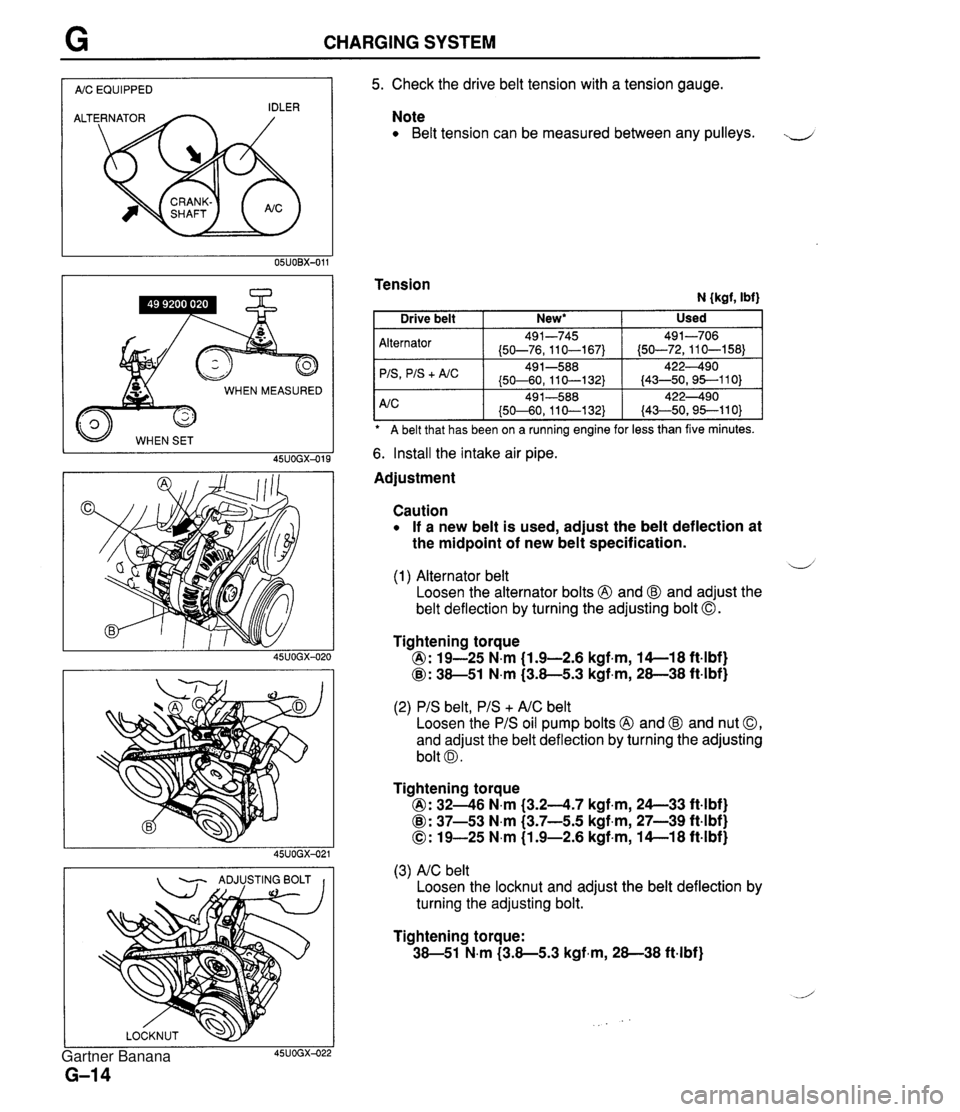
CHARGING SYSTEM I AIC EQUIPPED I WHEN MEASURED 45UOGX-015 - ADJUSTING BOLT I I 5. Check the drive belt tension with a tension gauge. Note Belt tension can be measured between any pulleys. J Tension N {kgf, Ibf) A belt that has been on a ruining engine for less than five minutes. Alternator 'IS
+ A/C 6. Install the intake air pipe. Used Drive belt Adjustment New* I Caution If a new belt is used, adjust the belt deflection at the midpoint of new belt specification. 491-745 (50-76,110-167) 49 1-588 (50-60, 11 0-1 32) d (1) Alternator belt Loosen the alternator bolts @ and @ and adjust the belt deflection by turning the adjusting bolt 0. 491-706 (50-72,110-158) 422490 (43-50,95--110) Tightening torque @: 19-25 N.m (1.9-2.6 kgf.m, 14-1 8 ft4bf) @: 38-51 N.m (3.8-5.3 kgf,m, 28-38 ft-lbf) (2) PIS belt, PIS + AIC belt Loosen the PIS oil pump bolts @ and @ and nut 0, and adjust the belt deflection by turning the adjusting bolt 0. Tightening torque @: 3246 N.m (3.24.7 kgf.m, 24--33 ft4bf) @: 37-53 N.m (3.7-5.5 kgf,m, 27-39 ft-lbf) 0: 19-25 N.m (1.9-2.6 kgf-m, 14-1 8 ft-lbf) (3) AIC belt Loosen the locknut and adjust the belt deflection by turning the adjusting bolt. Tightening torque: 38-51 N.m (3.8-5.3 kgf-m, 28-38 ft-lbf) Gartner Banana
Page 324 of 1708

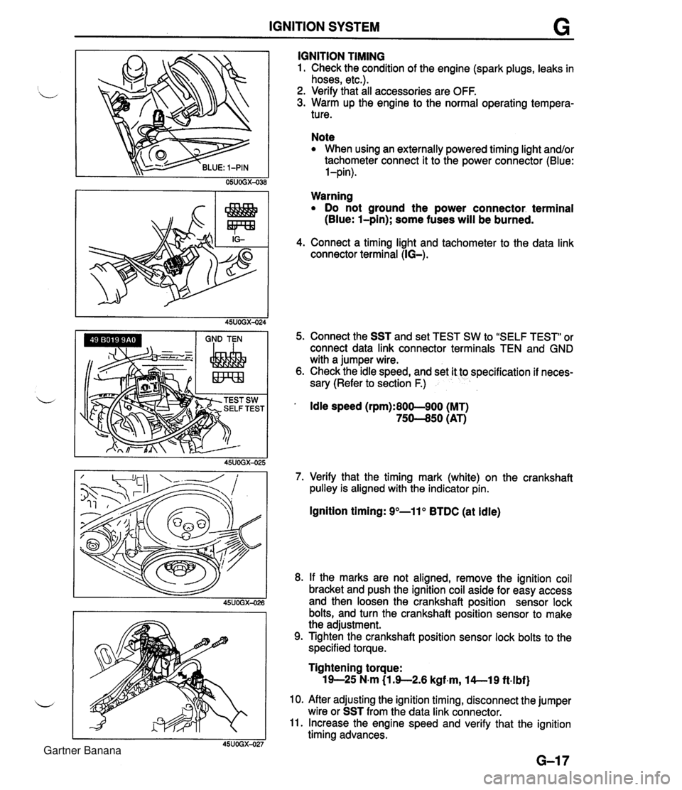
IGNITION SYSTEM G GND TEN I I I IGNITION TIMING 1. Check the condition of the engine (spark plugs, leaks in hoses, etc.). 2. Verify that all accessories are OFF. 3. Warm up the engine to the normal operating tempera- ture. Note When using an externally powered timing light and/or tachometer connect it to the power connector (Blue: l-pin). Warning Do not ground the power connector. terminal (Blue: l-pin); some fuses will be burned. 4. Connect a timing light and tachometer to the data link connector terminal (IG-). 5. Connect the SST and set TEST SW to "SELF TEST" or connect data link connector terminals TEN and GND with a jumper wire. 6. Check the idle speed, and set it to specification if neces- sary (Refer to section F.) ' Idle speed (rpm):800-900 (MT) 75-50 (AT) 7. Verify that the timing mark (white) on the crankshaft pulley is aligned with the indicator pin. Ignition timing: 9"-11" BTDC (at idle) 8. If the marks are not aligned, remove the ignition coil bracket and push the ignition coil aside for easy access and then loosen the crankshaft position sensor lock bolts, and turn the crankshaft position sensor to make the adjustment. 9. Tighten the crankshaft position sensor lock bolts to the specified torque. Tightening torque: 19-25 N-m (1 3-2.6 kgf~m, l4--19 ft.lbf) 10. After adjusting the ignition timing, disconnect the jumper wire or SST from the data link connector. 11. Increase the engine speed and verify that the ignition timing advances. Gartner Banana
Page 328 of 1708

STARTING SYSTEM G STARTING SYSTEM CIRCUIT DIAGRAM I TROUBLESHOOTING Check 1 1 No Magnetic switch gE only clicks when ignition switch is at START Check starter (Refer to page G-23) Check wire harness Check 2 NO MT . . . . 1. Depress clutch pedal 2. Check if voltage between interlock switch (starter side) and ground is approx. 12V AT . . . . 1. Shift into P or N range Check wire harness 2. Check if voltage between parwneutral switch (starter side) and ground is approx. 12v 1. Turn ignition switch to START position 2. Check if voltage between S terminal and ground is approx. 12V Check 3 1 No Check starter magnetic switch (Refer to page G-27) I I Check wire harness I MT . . . . Check if voltage between interlockswitch (igni- tion switch side) and ground is approx. 12V AT . . . . . Check if voltage between parwneutral switch (ignition switch side) and ground is approx. 12v Check starter interlock switch (Refer to page G-28) Check parwneutral switch (Refer to section K) Gartner Banana
Page 333 of 1708

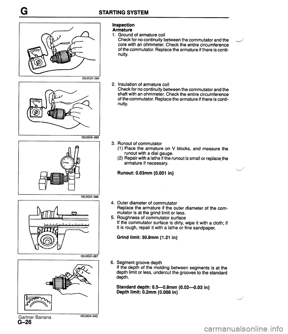
STARTING SYSTEM Inspection Armature 1. Ground of armature coil Check for no continuity between the commutator and the .J core with an ohmmeter. Check the entire circumference of the commutator. Replace the armature if there is conti- nuity. 2, Insulation of armature coil Check for no continuity between the commutator and the shaft with an ohmmeter. Check the entire circumference of the commutator. Replace the armature if there is conti- nuity. 3. Runout of commutator (1) Place the armature on V blocks, and measure the runout with a dial gauge. (2) Repair with a lathe if the runout is small or replace,the armature if necessary. -1' Runout: 0.03mm (0.001 in) 4. Outer diameter of commutator Replace the armature if the outer diameter of the com- mutator is at the grind limit or less. 5. Roughness of commutator surface If the commutator surface is dirty, wipe it with a cloth; if it is rough, repair it with a lathe or fine sandpaper. Grind limit: 30.8mm (1.21 in) 6. Segment groove depth If the depth of the molding between segments is at the depth limit or less, undercut the grooves to the standard depth. Standard depth: 0.5--0.8mm (0.02-4.03 in) Depth limit: 0.2mm (0.008 in) Gartner Banana
Page 335 of 1708

STARTING SYSTEM LIMIT 1 I 45UOGX-043 STARTER INTERLOCK SWITCH (MT) Brush If the brushes are worn beyond the wear limit or if the wear is near the limit, replace the brushes. CONTACT PLATES IGNITION SWITCH mm {in} IG1 ROD Standard Wear limit INTERLOCK SWITCH 62-7 - STARTER MT 17 (0.67) 11.5 (0.45) The clutch pedal must be depressed during starting for battery power to be supplied to the starter. AT 17.5 (0.69) 12.0 (0.47) Inspection 1. Disconnect the interlock switch connector. 2. Check continuity of the switch with an ohmmeter. Pedal Depressed Released Continuity Yes No 1 3. If not as specified, replace the interlock switch. Gartner Banana