lock MAZDA MX-5 1994 Owners Manual
[x] Cancel search | Manufacturer: MAZDA, Model Year: 1994, Model line: MX-5, Model: MAZDA MX-5 1994Pages: 1708, PDF Size: 82.34 MB
Page 406 of 1708

OUTLINE K POWER FLOW DIAGRAM 1. Torque converter 2. Oil pump 3. Input shaft 4. Fourth gear sun gear 5. Internal gear - 6. Fourth gear one-way clutch (4GR OWC) 7. Fourth gear brake band (4GR Brk.) OPERATION OF COMPONENTS 8. Fourth gear planetary pinion carrier 9. Direct clutch (D/C) 10. Intermediate shaft 11. Front clutch (F/C) 12. 2nd brake band (2nd Brk.) 13. Rear clutch (R/C) 14. Front planetary pinion carrier 15. Internal gear 16. Sun gear 17. Rear planetary pinion carrier 18. Low and reverse brake (L&R Brk.) 19. Internal gear 20. One-way clutch (OWC) 21. Output shaft C3 indicates operation although the band servo remains deactivated due to the large area of the release pressure side. The lockup control solenoid valve operates only during lockup. The 3-2 control solenoid valve operates momentarily during 3-2 downshift. The Fourth gear one-way clutch operates momentarily during 4-3 downshift. Gartner Banana
Page 407 of 1708

K OUTLINE FLUID PASSAGE LOCATIONS Transmission Case TO SECOND SERVO RELEASE SlDE TO DIRECT CLUTCH AND FOURTH GEAR SERVO RELEASE SlDE TO SECOND SERVO APPLY SI OIL PUMP DISCHARGE TORQUE CONVERTER PRESSURE TO REAR CLUTCH TO FRONT CLUTC OIL PUMP SUCTION , REAR LUBRICATION TO LOW AND REVERSE BRAKE OIL PUMP SUCTION TO FRONT CLUTCH TO DIRECT CLUTCH AND FOURTH GEAR SERVO RELEASE SlDE TO REAR CLUTCH / OIL PUMP DISCHARGE TORQUE CONVERTER PRESSURE Oil Pump OIL PUMP DISCHARGE FRONT LOCKUP CONTROL OIL PUMP SUCTION SOLENOID VALVE TORQUE CONVERTER PRESSURE 0i PUMP DISCHARGE Gartner Banana
Page 408 of 1708

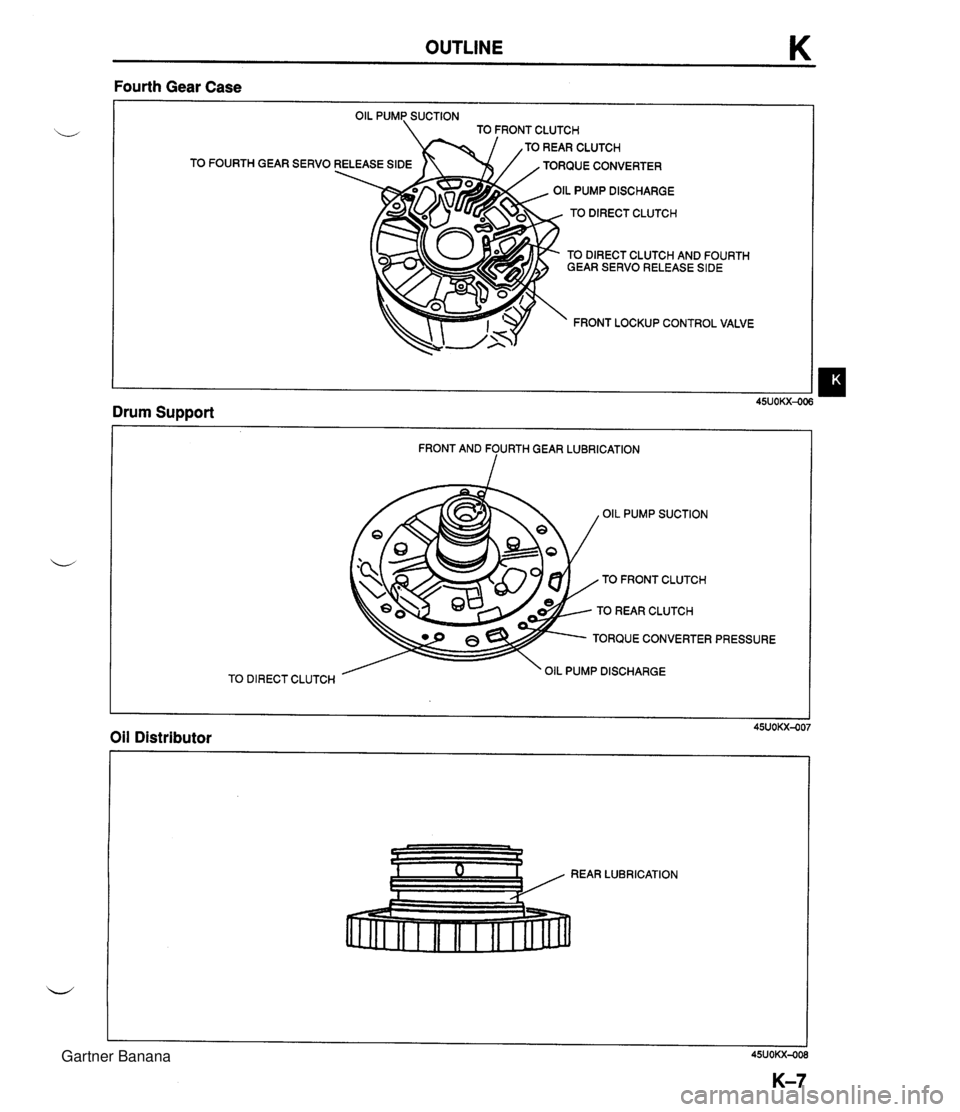
OUTLINE K Fourth Gear Case TO FRONT CLUTCH TOREARCLUTCH TO FOURTH GEAR SERVO RELEASE SIDE TORQUE CONVERTER OIL PUMP DISCHARGE TO DIRECT CLUTCH TO DIRECT CLUTCH AND FOURTH GEAR SERVO RELEASE SlDE FRONT LOCKUP CONTROL VALVE Drum Support - TO DIRECT CLUTCH FRONT AND FOURTH GEAR LUBRICATION 1 OIL PUMP SUCTION TO FRONT CLUTCH TO REAR CLUTCH TORQUE CONVERTER PRESSURE OIL PUMP DISCHARGE Oil Distributor Gartner Banana
Page 411 of 1708

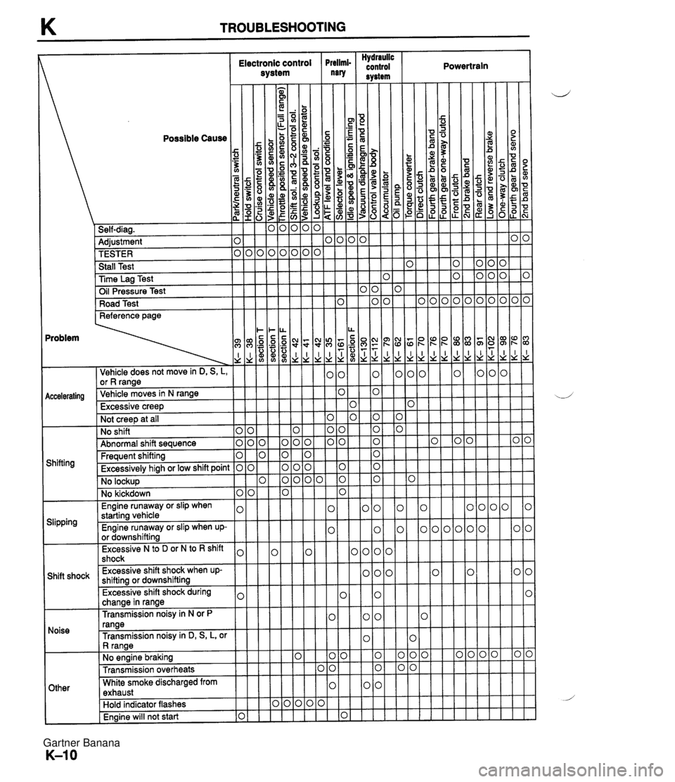
K TROUBLESHOOTING Hydraulic Electronic control Prelimi- control Powertrain system "8' svstem rieference page I I \dd I Vehicle does not move in D, S, L, or R range iccelerating Vehicle moves in N range Excessive creep Not creep at all No shift 0 0 Abnormal shift sequence 0 0 Frequent shifting 0 Shifting Excessivelv hiah or low shift point 0 0 . - No lockup I No kickdown l0k I - 1 Engine runaway or slip when \,I starting vehicle- V Slipping Engine runaway or slip when up- I I I or downshifting I I ] Excessive N to D or N to R shift 1,1 shock w I change in range I Transmission noisy in N or P Noise range Transmission noisy in D, S, L, or I 1 I R ranae I I Other .. - - ( No engine braking I Transmission overheats I I White smoke discharged from exhaust Engine will not start 10 1 Gartner Banana
Page 413 of 1708

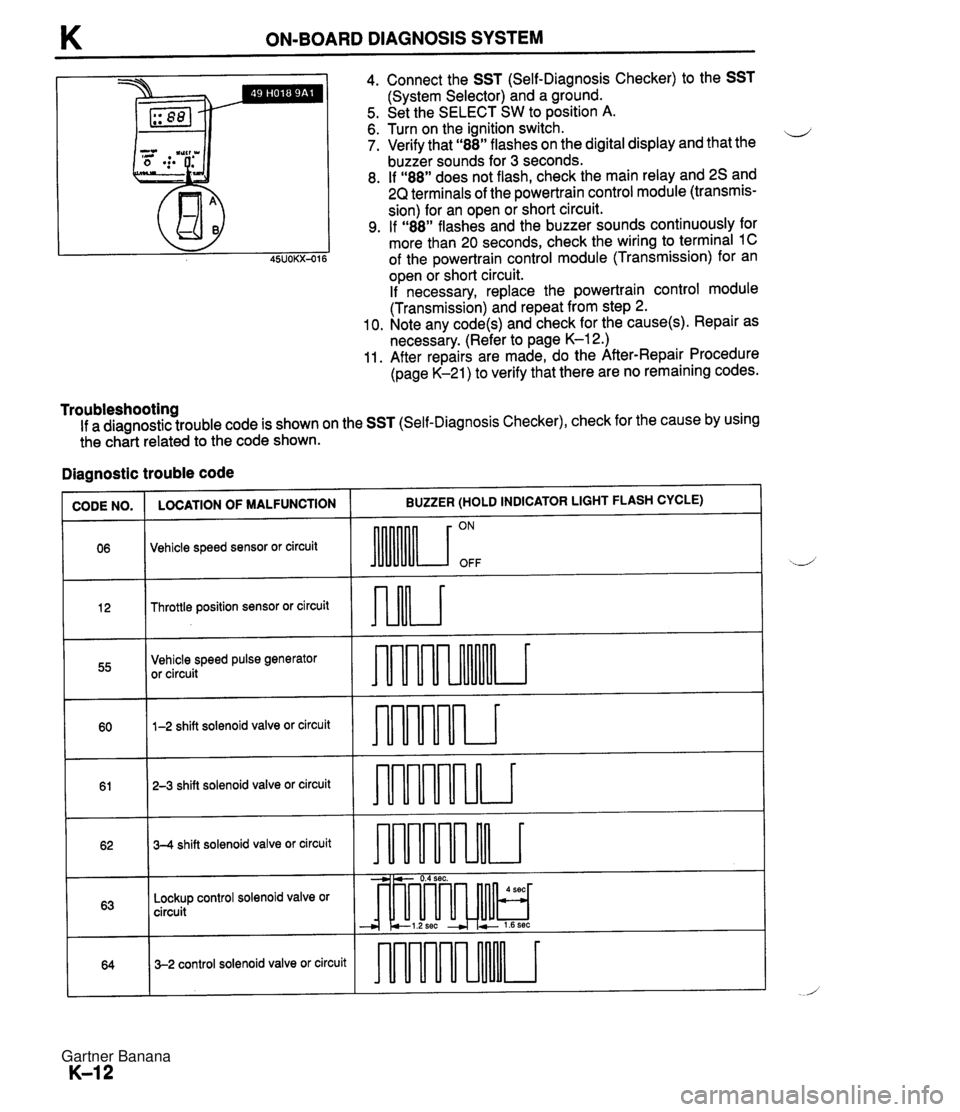
K ON-BOARD DIAGNOSIS SYSTEM Ill I 4. Connect the SST (Self-Diagnosis Checker) to the SST (System Selector) and a ground. 5. Set the SELECT SW to position A. 6. Turn on the ignition switch. ii 7. Verify that "88" flashes on the digital display and that the buzzer sounds for 3 seconds. 8. If "88" does not flash, check the main relay and 2s and 2Q terminals of the powertrain control module (transmis- sion) for an open or short circuit. 9. If "88" flashes and the buzzer sounds continuously for more than 20 seconds, check the wiring to terminal 1C of the powertrain control module (Transmission) for an open or short circuit. If necessary, replace the powertrain control module (Transmission) and repeat from step 2. 10. Note any code(s) and check for the cause(s). Repair as necessary. (Refer to page K-12.) 11. After repairs are made, do the After-Repair Procedure (page K-21) to verify that there are no remaining codes. Troubleshooting If a diagnostic trouble code is shown on the SST (Self-Diagnosis Checker), check for the cause by using the ch&t related to the code shown. Diagnostic trouble code ~U)DE NO. 1 LOCATION OF MALFUNCTION I BUZZER (HOLD INDICATOR LIGHT FLASH CYCLE) Throttle position sensor or circuit 06 Vehicle speed sensor or circuit 55 ON OFF Vehicle speed pulse generator or circuit 60 - 61 1-2 shift solenoid valve or circuit 62 - -- - 3-2 control solenoid valve or circuit 64 T 2-3 shift solenoid valve or circuit 63 - 3-4 shift solenoid valve or circuit -----a Lockup control solenoid valve or circuit -- --i---- - - - audrur - -, -. - 0.4 sec. - --I-& cl.2sec + 2 1.6sec * - 4 sec - - Gartner Banana
Page 420 of 1708

ON-BOARD DIAGNOSIS SYSTEM - DIAGNOSTIC TROUBLE CODE No.63 LOCKUP CONTROL SOLENOID VALVE STEP INSPECTION ACTION re there any poor connections at sole- id valve and powertrain control module ransmission) connectors? Yes Repair or replace connector Go to next step onnect a circuit tester to terminal as 10wn output voltage of lockup control sole- >id valve at powertrain control module ransmission) Yes Check wiring and go to step 5 page K-45 (+) term. 2K B+: Battery positive voltage Go to next step (-)term. Lockup Ground Solenoid - - isconnect 20-pin powertrain control ~odule (transmission) connector , resistance between terminal 2K and ,ound OK? Voltage (V) B+ Yes Condition Solenoid ON, Go to step 5 No Yes Go to next step Resistance: 13--2752 isconnect solenoid connector resistance between ground and termi- 31 B of lockup control solenoid valve OK? page K-42 Check wiring and connectors form powertrain control module (transmission) to lockup control solenoid valve If OK, go to next step If not OK, repair wiring and/or connector Resistance: 13--2752 No Yes No Replace lockup control solenoid valve isconnect the negative battery cable for :least 20 seconds and depress the brake sdal onnect the battery cable and recheck for ~de diagnostic trouble code displayed? page K-21 Replace powertrain control module (transmission) page K-45 Intermittent poor connection Check for cause Gartner Banana
Page 430 of 1708

ROAD TEST K ROAD TEST A road test is necessary to inspect for problems in the different gear ranges. If a range or function tar- b geted by the road test is found to have any problem, refer to the ELECTRONIC SYSTEM COMPONENT segment or the TRANSMISSION, OIL COOLER, DRIVE PLATE, and SHIFT MECHANISM segments of this section. Do the road test only when the ATF is 50-80°C (1 22-1 76°F). D-RANGE TEST Shift Point, Shift Pattern, and Shift Shock 1. Shift the selector lever to D range and select the Normal mode. 2. Accelerate the vehicle with half-and wide open throttle opening. 3. Verify that 1-2, 2-3, and 3-4 upshifts, downshifts, and lockup are obtained. The shift points must be as shown in the D range (Normal) shift diagram. Note There is fourth gear is any of the following conditions. A The cruise control is operating, and there is an 8kmIh (5 mph} difference between the preset cruise speed and the vehicle speed. B The SET or RESUME switch is ON. There is no lockup when water temperature is below 50°C (1 22°F) or in the throttle valve closed posi- tion. 4. Check the upshifts for shift shock or slippage in the same manner. 5. While driving in overdrive, shift the selector lever to S range and verify that 4-3 downshift immediately occurs, then decelerate and verify that engine braking effect is felt in only third gear and 2nd gears. D-range (Normal) shift diagram p'yJ ..,,*sw.. LOCKUP AVAILABLE WHEN ACCELERATING AND CRUSING LOCKUP AVAILABLE WHEN COASTING 0 20 (1 2) 40 (25) 60 (37) 80 {50) 100 (63) 1 20 (75) 140 (87) 1 60 (99) VEHICLE SPEED kmlh {mph) Gartner Banana
Page 431 of 1708

ROAD TEST D range (Power) shift diagram = LOCKUP AVAILABLE WHEN ACCELERATING AND CRUSING LOCKUP AVAILABLE WHEN COASTING VEHICLE SPEED kmh (mph) 45UOKX-51 6. Select the Hold mode. 7. Accelerate the vehicle and check 2-3 up-and downshifts, verify that no 1st and no fourth gear is ob- tained, and verify that the 2-3 shift points are as shown in the D range (Hold) shift diagram. D-range (Hold) shift diagram 0 20 (1 2) 40 (25) 60 (37) 80 (50) 100 {63) 120 (75) 140 {87) 160 (99) VEHICLE SPEED kmlh (mph) Gartner Banana
Page 432 of 1708

ROAD TEST K Evaluation I No lockup shift Condition No 1-2 up or downshift No 2-3 up or downshift No 3-4 up or downshift I Stuck lockup control solenoid valve Stuck locku~ control valve Possible Cause Stuck 1-2 shift solenoid valve Stuck 1-2 shift valve Stuck 2-3 shift solenoid valve Stuck 2-3 shift valve Stuck 3-4 shift solenoid valve Stuck 3-4 shift valve Incorrect shift point I No enaine brakina effect I Worn clutches, brakes I Misadjusted throttle position sensor Sticking shift valves Excessive shift shock or slippage Noise and Vibration Drive the vehicle in fourth gear (lockup), fourth gear (no lockup), and third gear (Hold) and listen closely for any out of the ordinary noise or vibration. The torque converter, propeller shaft, and differential can be sources of abnormal noise and vibration if they are not functioning properly. Check these when searching for sources of noise and vibration. Stuck accumulators Stuck or no one-way check orifice Stuck 3-2 control solenoid valve Stuck 3-2 control valve Worn clutches, brakes, or one-way clutch Kickdown Drive the vehicle in fourth gear, third gear, and 2nd gear and check that kickdown occurs for 4-+3,4-+2, 4+1,3+2,3+1, 2+1, and that the shift points are as shown in the shift diagram. ,U (Refer to pages K-29, 30.) S-RANGE TEST Shift Pattern For this test it is not necessary to inspect shift shock and shift points, since they are almost exactly the same as those for the D-range test. However, in the D-range (Normal) shift diagram, the shift points are different. In S range, the shift patterns for Normal mode are the same. 1. Shift the selector lever to S range and select the Normal mode. 2. Accelerate the vehicle and verify that 1-2 and 2-3 up-and downshifts are obtained, and that no fourth gear and no lockup (below approx. 100 kmlh (63 mph}) are obtained. 3. While driving in S range (Normal mode) and third gear, select the Hold mode and verify that third gear is held until ihe 3-2 downshift point as shown in the S range (Hold) shift diagram is achieved. 4. Accelerate the vehicle in S range (Hold mode) and verify that 2nd gear is held. S-range (Power) shift diagram LOCKUP AVAILABLE WHEN ACCELERATING AND CRUSING LOCKUP AVAILABLE WHEN COASTING -. - VEHICLE SPEED kmlh (rnph} Gartner Banana
Page 433 of 1708

ROAD TEST (Hold) shift diagram LOCKUP AVAILABLE WHEN COASTING 818 718 - 618 - 518 ' 418 - 3/8 ' 218 - 118 - 018 0 20 (1 2) 40 (25) 60 (37) 80 (50) 100 (63) 120 (75) 140 (87) 160 (99) VEHICLE SPEED kmh {mph} Noise and Vibration Drive the vehicle in 2nd (Hold) and listen closely for any out of the ordinary noise or vibration. The torque converter, propeller shift, and differential can be sources of abnormal noise and vibration if they are not functioning properly. Check these when searching for sources of noise and vibration. L-RANGE TEST Shift Pattern For this test it is not necessary to inspect shift shock and shift points, since they are almost exactly the same as those for the D-range test. However, in the D-range (Normal) shift diagram, the shift points are different. ,, In L-range, the shift patterns for Normal mode are the same. 1. Shift the selector lever to L-range and select the Normal mode. 2. Accelerate the vehicle and verify that 1-2 up and downshifts are obtained, and that no third gear, no fourth gear, and no lockup are obtained. 3. Drive in 1 st gear, then decelerate and verify that engine braking effect is felt. 4. While driving in D-range (Hold mode) and third gear, shift the selector lever to L-range and verify that third gear is held until the 3-2 downshift point as shown in the L-range (Hold) shift diagram, and that 2nd gear is held until 2-1 downshift point is achieved. 5. Accelerate the vehicle in L-range (Hold mode) and verify that 1 st gear is held. L-range (Power) shift diagram LOCKUP AVAILABLE WHEN COASTING o 20 (12) 40 (25) 60 (37) 80 (50) 100 163) i 20 (75) 14dp7) 160 pgj VEHICLE SPEED kwh {mph) Gartner Banana