check engine MAZDA PROTEGE 1992 Workshop Manual
[x] Cancel search | Manufacturer: MAZDA, Model Year: 1992, Model line: PROTEGE, Model: MAZDA PROTEGE 1992Pages: 1164, PDF Size: 81.9 MB
Page 471 of 1164

STARTING SYSTEM G
STARTER INTERLOCK SWITCH (MTX)
CONTACT
IGNITION SWITCH
IG2 ROD
p IG1 ‘NTERlfM$TCH
i BATTERY
I
STARTER
For operator safety, if the clutch pedal is not depressed during starting, battery power will not be supplied
to the starter and the engine will not crank.
Interlock Switch
Inspection
1. Disconnect the interlock switch connector.
2. Connect an ohmmeter to the switch.
3. Check the continuity.
Clutch pedal
----- I_
Depressed
Released 4.
Replace the switch if necessary.
Continuity
--
Yes
No
G-31
Page 650 of 1164

ENGINE SPEED SENSING POWER STEERING
23UONX-03
03UONX-032
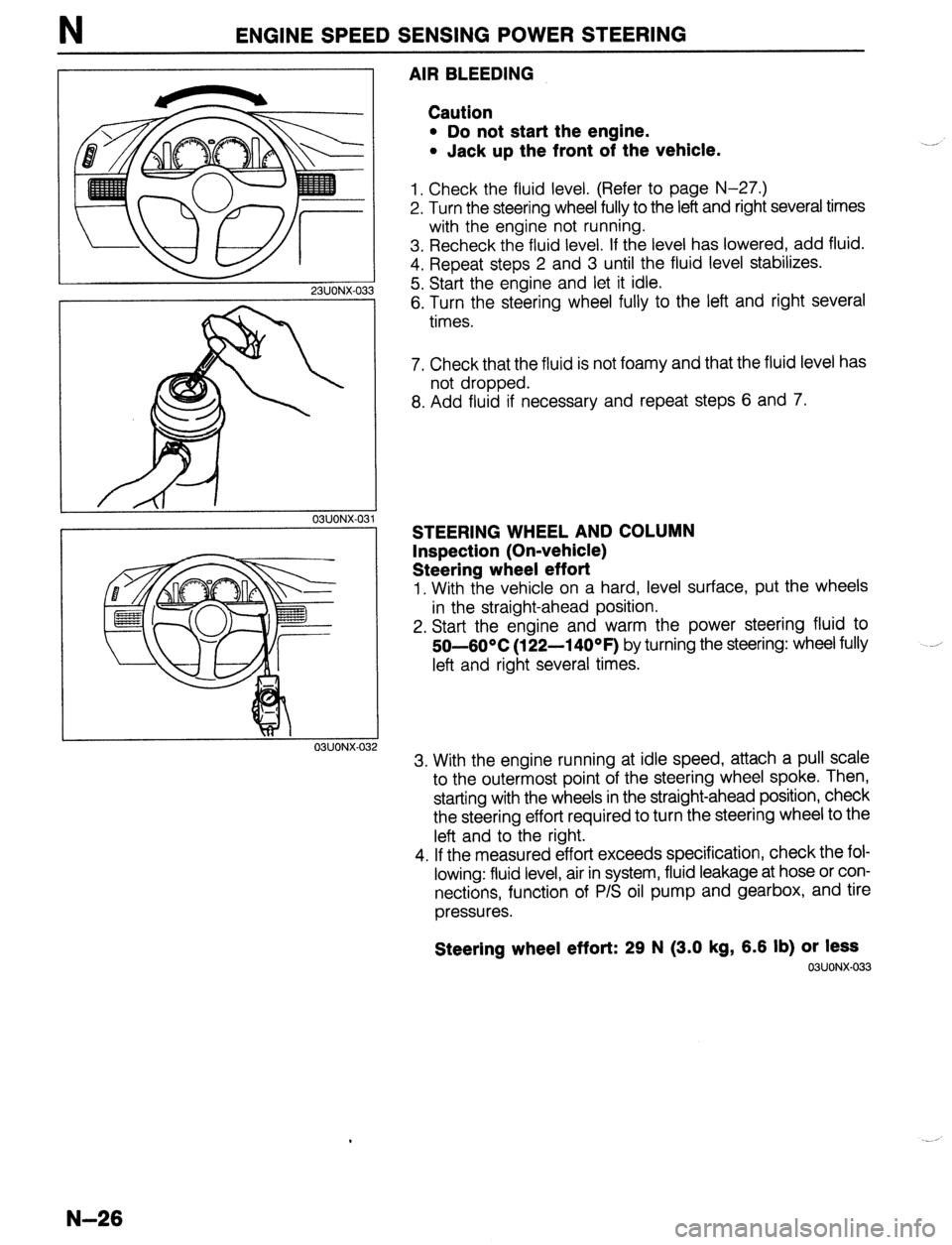
AIR BLEEDING
Caution
l Do not start the engine.
l Jack up the front of the vehicle.
1. Check the fluid level. (Refer to page N-27.)
2. Turn the steering wheel fully to the left and right several times
with the engine not running.
3. Recheck the fluid level. If the level has lowered, add fluid.
4. Repeat steps 2 and 3 until the fluid level stabilizes.
5. Start the engine and let it idle.
6. Turn the steering wheel fully to the left and right several
times.
7. Check that the fluid is not foamy and that the fluid level has
not dropped.
8. Add fluid if necessary and repeat steps 6 and 7.
STEERING WHEEL AND COLUMN
Inspection (On-vehicle)
Steering wheel effort
1. With the vehicle on a hard, level surface, put the wheels
in the straight-ahead position.
2. Start the engine and warm the power steering fluid to
50-60°C
(122-14OOF) by turning the steering: wheel fully
left and right several times.
3. With the engine running at idle speed, attach a pull scale
to the outermost point of the steering wheel spoke. Then,
starting with the wheels in the straight-ahead position, check
the steering effort required to turn the steering wheel to the
left and to the right.
4. If the measured effort exceeds specification, check the fol-
lowing: fluid level, air in system, fluid leakage at hose or con-
nections, function of P/S oil pump and gearbox, and tire
pressures.
Steering wheel effort: 29 N (3.0 kg, 6.6 lb) or less 03UONX-033
N-26
Page 651 of 1164

ENGINE SPEED SENSING POWER STEERING N
r-
-l
03UONX-034
POWER STEERING FLUID
On-vehicle Inspection
Inspection of fluid level
Caution
l Add only the specified power steering fluid.
1. Verify that the fluid level is between the H and L marks.
2. Add or remove fluid if not within specification.
Inspection of fluid leakage
Start the engine. Turn the steering wheel fully left and right to apply fluid pressure; then check for fluid leakage.
Caution
+ To prevent damage, do not keep the steering wheel in the fully turned position for more than
15 seconds.
Note
l The points where fluid leakage may occur are indicated by the arrows in the figure.
03UONX-035
N-27
Page 657 of 1164

ENGINE SPEED SENSING POWER STEERING N
I I
-.
* :I
-3==T
I
, 93GONX-031
93GONX-03 2
I
93GONX-03 3
I
03UONX-822
t
~ t
93WJNX-03
Oil seal and bearing
1. Use the SST to remove the bearing and the oil seal from
the plug.
Caution
l The oil seal can not be reused.
Outer box assembly
1. Use the SST to remove the outer box.
Oil seal and inner guide
1, Use the SST to remove the oil seal and inner guide toward
the cylinder side.
Caution
l The oil seal can not be reused.
lnspectlon
Steerlng rack
1. Check the rack for cracking or other damage or for abnor-
mal wear of the teeth; replace it if necessary.
2. Check the seal ring installation part of the rack for abnor-
mal wear or damage; replace it if necessary.
3. Use V blocks to support both ends of the large-diameter
part of the rack; check for excessive bending; replace it if
necessary.
Bending limit: 0.15mm (0.006 In) (near rack center)
Plug
1. Check for scratches or other damage at the oil seal instal-
lation inner diameter; replace it if necessary.
Page 658 of 1164

N ENGINE SPEED SENSING POWER STEERING
23UOiX-055
23UONX-057
23UONX-05s
23UONX-05
Assembly
1. Mounting bracket and mounting rubber (gear housing
side)
(1) install the mounting bracket and mounting rubber (gear
housing side) to the gear box. ,
2. Steering rack
(1) Install a new O-ring and new seal ring to the rack’s
piston.
(2) After installing the seal ring, seat it properly at the pis-
ton circumference.
(3) Install the oil seal and inner guide to the
SST.
(4) Using the SST, place the oil seal and inner guide at the
edge of the steering rack’s pinion.
(5) After mounting the steering rack to the gear box, use
a press to install the oil seal and inner guide to the cor-
rect position.
Caution
l When pressing in, do not apply a load pressure of
more than 29,430 kPa (300 kg/cm2, 4,266 psi), be-
cause to do so will damage the oil seal and inner
guide.
l Apply grease to the seal ring, O-ring oil seal and in-
ner guide.
23UONX-056
3. Outer box assembly
(1) Install a new U-gasket and O-ring to the outer box.
(2) After installing the SST to the rack, install the outer box,
and use the
SST to tighten.
Tightening torque:
39-49 N-m (4-S m-kg, 29-36 ft-lb)
4. Cylinder air-tightness check
(1) Install the SST to the cylinder part of the gear housing.
(2) Using a vacuum pump, apply a vacuum of 400 mmHg
and check to be sure that the vacuum is maintained for
30 seconds.
(3) If there is any leakage, replace the oil seal.
5. Oil seal
(1) Use the SST to install a new oil seal to the gear housing.
Note
l Apply grease to the oil seal.
N-34
Page 663 of 1164

ENGINE SPEED SENSING POWER STEERING
93GONX-05:
93GONX-056
93GONX-O!
93GONX-05
Disassembly note
Oil pump
Note
l As shown in the figure, when securing the oil pump
in a vise, be sure to use the SST so that force is not
applied to the pulley or shaft.
Assembly note
Rotor
1. Install the rotor to the shaft with the rotor’s identification mark
facing upward.
Cam ring
1. Install the cam ring so that its identification mark is facing
downward.
Vane
1. Install the vanes (10 pieces) to the rotor, with the R part of
the vanes facing outward.
Inspection
Note
l Replace the pump assembly if necessary.
Pump body
1. Check the front and rear pump bodies for cracking or oth-
er damage and for abnormal wear of the moving surface
of the rotor.
N-39
Page 664 of 1164

N ENGINE SPEED SENSING POWER STEERING
93GONX-05
I 93GONX-05!
Cam ring, rotor, vanes, side plate
1. Check the moving surface of the cam ring’s vanes for ab-
normal wear.
2. Check the moving surface of the side plate and the pump
bodies for abnormal wear.
3. Check the moving surface of the vane cam ring for abnor-
mal wear.
4. Check the clearance of the rotor and vanes.
4
Control valve and spring
1. Check the control valve for cracking and other damage, for
clogging, and for abnormal wear of the moving part.
2. Check the spring for damage.
Page 665 of 1164

ENGINE SPEED SENSING POWER STEERING N
P/S
23UONX-04!
PULLEY
P/S AND A/C
23UONX-04
DRIVE BELT
Inspection
1. Check the drive belts for wear, cracks, and fraying. Replace
as necessary.
2. Verify that the drive belts are correctly mounted on the
pulleys.
3. Check the drive belt deflection by applying moderate pres-
sure (98 N,
10 kg, 22 lb) midway between the pulleys.
Note
l Measure the belt deflection between the specified
pulleys.
0 A belt is considered “New” if it has been used on
a running engine for less than five minutes.
Set the deflection specification below accordingly.
* Check the belt deflection when the engine is cold,
or at least 30 minutes after the engine has stopped.
Deflection
mm (in)
New Used Limit
8-9.0 (0.31-0.35) 9.0-10.0 (0.35-0.39) 11.5 (0.45)
4. If the deflection is not within specification, adjust it.
23UONX-047
Drive belt tension check
WHEN SET
I
23UONX-048
Note
l Belt tension can be checked in place of belt
deflection.
aBelt tension can be measured between any two
pulleys.
Using the SST check the belt tension.
Tension
N (kg, lb)
New
491-589
(50-60, 11 O-l 32) Used
422-491
(43-50, 95-l 10) Limit
245
(25, 55)
N-41
Page 679 of 1164

CONVENTIONALBRAKESYSTEM P
1 SUOPX-001
03UOPX-03
0
o3uoPx-os
0
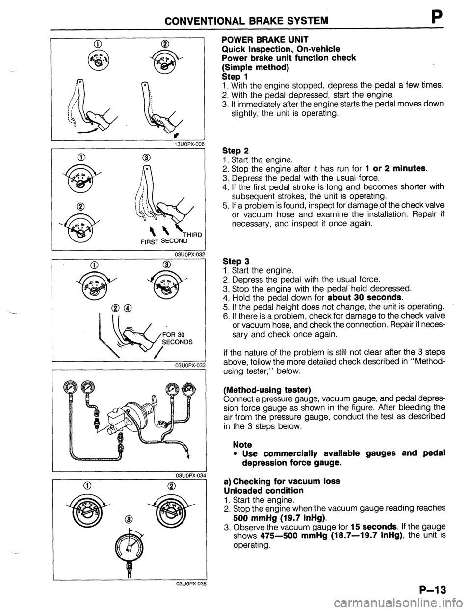
POWER BRAKE UNIT
Quick Inspection, On-vehicle
Power brake unit function check
k:;;p{e method)
1. With the engine stopped, depress the pedal a few times.
2. With the pedal depressed, start the engine.
3. If immediately after the engine starts the pedal moves down
slightly, the unit is operating.
Step 2
1. Start the engine.
2. Stop the engine after it has run for
1 or 2 minutes.
3. Depress the pedal with the usual force.
4. If the first pedal stroke is long and becomes shorter with
subsequent strokes, the unit is operating.
5. If a problem is found, inspect for damage of the check valve
or vacuum hose and examine the installation. Repair if
necessary, and inspect it once again.
Step 3
1. Start the engine.
2. Depress the pedal with the usual force.
3. Stop the engine with the pedal held depressed.
4. Hold the pedal down for
about 30 seconds.
5. If the pedal height does not change, the unit is operating.
6. If there is a problem, check for damage to the check valve
or vacuum hose, and check the connection. Repair if neces-
sary and check once again.
If the nature of the problem is still not clear after the 3 steps
above, follow the more detailed check described in “Method-
using tester,” below.
(Method-using tester)
Connect a pressure gauge, vacuum gauge, and pedal depres-
sion force gauge as shown in the figure. After bleeding the
air from the pressure gauge, conduct the test as described
in the 3 steps below.
Note
l Use commercially available gauges and pedal
depression force gauge.
a) Checking for vacuum loss
Unloaded condition
1. Start the engine.
2. Stop the engine when the vacuum gauge reading reaches
500 mmHg (19.7 inHg).
3. Observe the vacuum gauge for 15 seconds. If the gauge
shows 475-500
mmHg (18.7-19.7 inHg), the unit is
operating.
P-13
Page 680 of 1164

P CONVENTIONAL BRAKE SYSTEM
0 8
500 mmHg
(19.7 inHg)
96 N (20 kg, 44 lb)
03UOPX-03
03UOPX-03
03UOPX-031
Loaded condition
1. Start the engine.
2. Depress the brake pedal with a force of 196 N (20 kg, 44
lb).
3. With the brake pedal depressed, stop the engine when the
vacuum gauge reading reaches 500 mmHg (19.7 inHg).
4. Observe the vacuum gauge for 15 seconds. If the gauge
shows 475-500 mmHg (18.7-19.7 inHg), the unit is
operating.
b) Checking for hydraulic pressure
1. If with the engine stopped (vacuum 0 mmHg) the fluid pres-
sure is within specification, the unit is operating.
Pedal force Fluid pressure
196 N (20 kg, 44 lb) 1 1,177 kPa (12 kg/cm2, 171 psi) min
2. Start the engine. Depress the brake pedal when the vacu-
um reaches 500 mmHg (19.7 inHg). If the fluid pressure
is within specification, the unit is operating.
Pedal force Fluid pressure
196 N (20 kg, 44 lb) 7,063 kPa (72 kg/cm’, 1,024 psi)
P-14