check engine MAZDA PROTEGE 1992 Workshop Manual
[x] Cancel search | Manufacturer: MAZDA, Model Year: 1992, Model line: PROTEGE, Model: MAZDA PROTEGE 1992Pages: 1164, PDF Size: 81.9 MB
Page 681 of 1164
CONVENTIONAL BRAKE SYSTEM P
03UOPX-039
ARROW MARK
23UOPX-Old
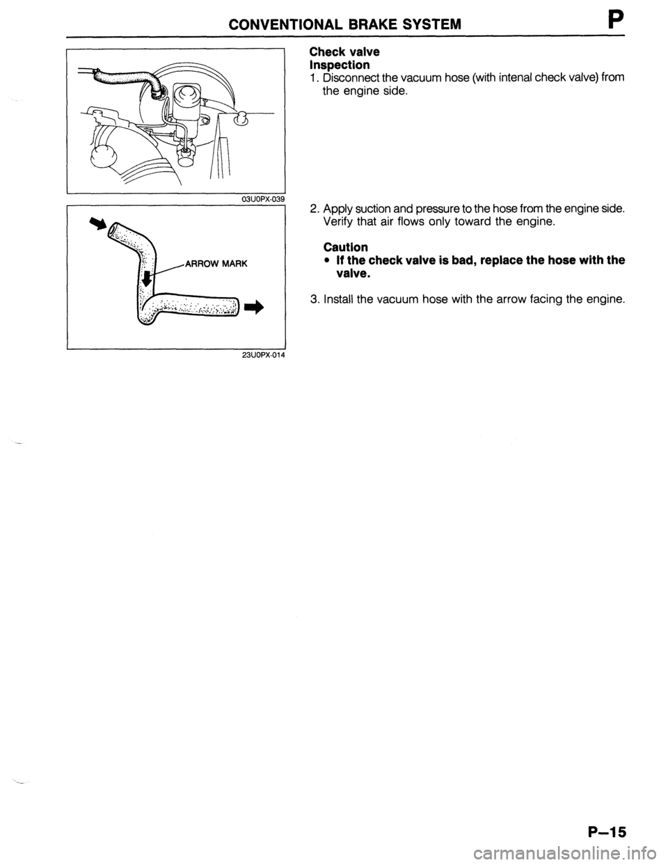
Check valve
Inspection
1. Disconnect the vacuum hose (with intenal check valve) from
the engine side.
2. Apply suction and pressure to the hose from the engine side.
Verify that air flows only toward the engine.
Caution
l If the check valve is bad, replace the hose with the
valve.
3. Install the vacuum hose with the arrow facing the engine.
P-15
Page 697 of 1164
PARKING BRAKE SYSTEM
PARKING BRAKE SYSTEM
TROUBLESHOOTING GUIDE
Problem
Brakes do not
release
Parking brake does
not hold well Possible cause
Improper return of parking brake cable or improper ad-
justment
Excessive lever stroke
Brake cable stuck or damaged
Brake fluid or oil on pad or lining
Hardening of pad / lining surface or poor contact Remedy Repair or adjust
Adjust
Repair or replace
Clean or replace
Grind or replace Page P-32
P-31
P-32
P-i,28
ONOPX-080
PARKING BRAKE SHOE
Removal / Inspection / Installation
Disc brake
Removal and Installation (Refer to page P-23)
Inspection (Refer to page P-25)
Drum brake
Removal and Installation (Refer to page P-28)
Inspection (Refer to page P-29)
03u0Px-081
13UOPX-021
03UOPX-08
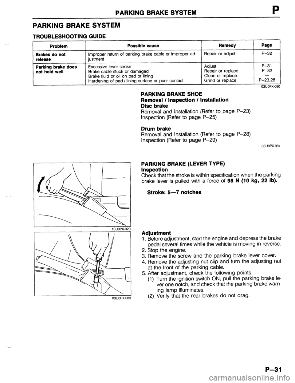
PARKING BRAKE (LEVER TYPE)
Inspection
Check that the stroke is within specification when the parking
brake lever is pulled with a force of 98 N (IO
kg, 22 lb).
Stroke: 5-7 notches
Adjustment
1. Before adjustment, start the engine and depress the brake
pedal several times while the vehicle is moving in reverse.
2. Stop the engine.
3. Remove the screw and the parking brake lever cover.
4. Remove the adjusting nut clip and turn the adjusting nut
at the front of the parking cable.
5. After adjustment, check the following points:
(1) Turn the ignition switch ON, pull the parking brake le
ver one notch, and check that the parking brake warn-
ing lamp illuminates.
(2) Verify that the rear brakes do not drag.
P-31
Page 713 of 1164
WHEEL ALIGNMENT
WHEEL ALIGNMENT
PRE-INSPECTION
1. Check the tire inflations and set to the recommended pressure, if necessary.
2. Inspect the front wheel bearing play; replace the bearing if necessary.
3. inspect the wheel and tire runout.
4. Inspect the ball joints and steering linkage for any excessive looseness.
5. The vehicle must be on level ground and have no luggage or passenger load.
6. The difference in height between the left and right sides from the center of the wheel to the fender brim
must not exceed
10mm (0.39 in).
7. Shake the vehicle to check operation of the shock absorbers.
03UORX.007
FRONT WHEEL ALIGNMENT
Specifications
item
Specifications
Maximum Inner 4o” f: 2O
steering angle Outer
33O f 2O
Total mm (in) 2 f 3 (0.08 f 0.12)
toe-in dearee 0.20 f 0.30 Wheel alignment
(*‘Unladen) Front
*I Fuel tank full; radiator coolant and Camber angle -0005 * 45’
Caster angle 1°55’ f 55’
Kingpin angle 12O25’
engine oil at specified level; and spare tire, jack, and tools in designated positions.
23UORX-008
I
I 23UORX-023
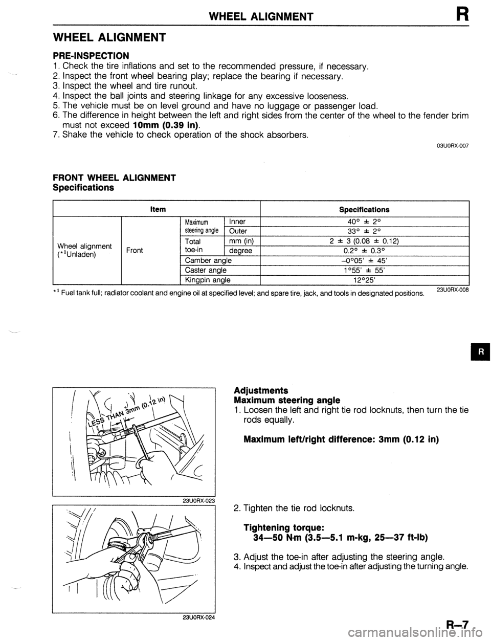
Adjustments
Maximum steering angle
1. Loosen the left and right tie rod locknuts, then turn the tie
rods equally.
Maximum left/right difference: 3mm (0.12 in)
2. Tighten the tie rod locknuts.
Tightening torque:
34-50 N-m (3.5-5.1 m-kg, 25-37 ft-lb)
3. Adjust the toe-in after adjusting the steering angle.
4. Inspect and adjust the toe-in after adjusting the turning angle.
I 23UORX-024
R-7
Page 917 of 1164
WARNING SYSTEM T
13UOTX-07
63U15X-05
, I//
‘nF -
-
-
FUEL
13UOTX.08C
- CHARGE
13UOTX-08
13UOTX-08
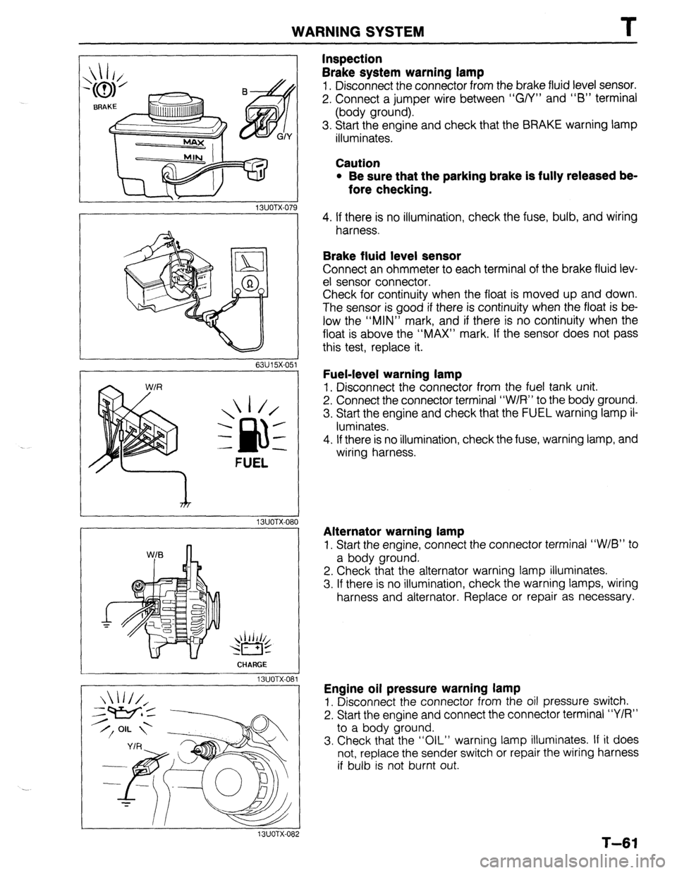
Inspection
Brake system warning lamp
1. Disconnect the connector from the brake fluid level sensor.
2. Connect a jumper wire between “G/Y” and “6” terminal
(body ground).
3. Start the engine and check that the BRAKE warning lamp
illuminates.
Caution
l Be sure that the parking brake is fully released be-
fore checking.
4. If there is no illumination, check the fuse, bulb, and wiring
harness.
Brake fluid level sensor
Connect an ohmmeter to each terminal of the brake fluid lev-
el sensor connector.
Check for continuity when the float is moved up and down.
The sensor is good if there is continuity when the float is be-
low the “MIN” mark, and if there is no continuity when the
float is above the “MAX” mark. If the sensor does not pass
this test, replace it.
Fuel-level warning lamp
1. Disconnect the connector from the fuel tank unit.
2. Connect the connector terminal “W/R” to the body ground.
3. Start the engine and check that the FUEL warning lamp il-
luminates.
4. If there is no illumination, check the fuse, warning lamp, and
wiring harness.
Alternator warning lamp
1. Start the engine, connect the connector terminal “W/B” to
a body ground.
2. Check that the alternator warning lamp illuminates.
3. If there is no illumination, check the warning lamps, wiring
harness and alternator. Replace or repair as necessary.
Engine oil pressure warning lamp
1. Disconnect the connector from the oil pressure switch.
2. Start the engine and connect the connector terminal “Y/R”
to a body ground.
3. Check that the “OIL” warning lamp illuminates. If it does
not, replace the sender switch or repair the wiring harness
if bulb is not burnt out.
T-61
Page 918 of 1164
T
I WARNING SYSTEM
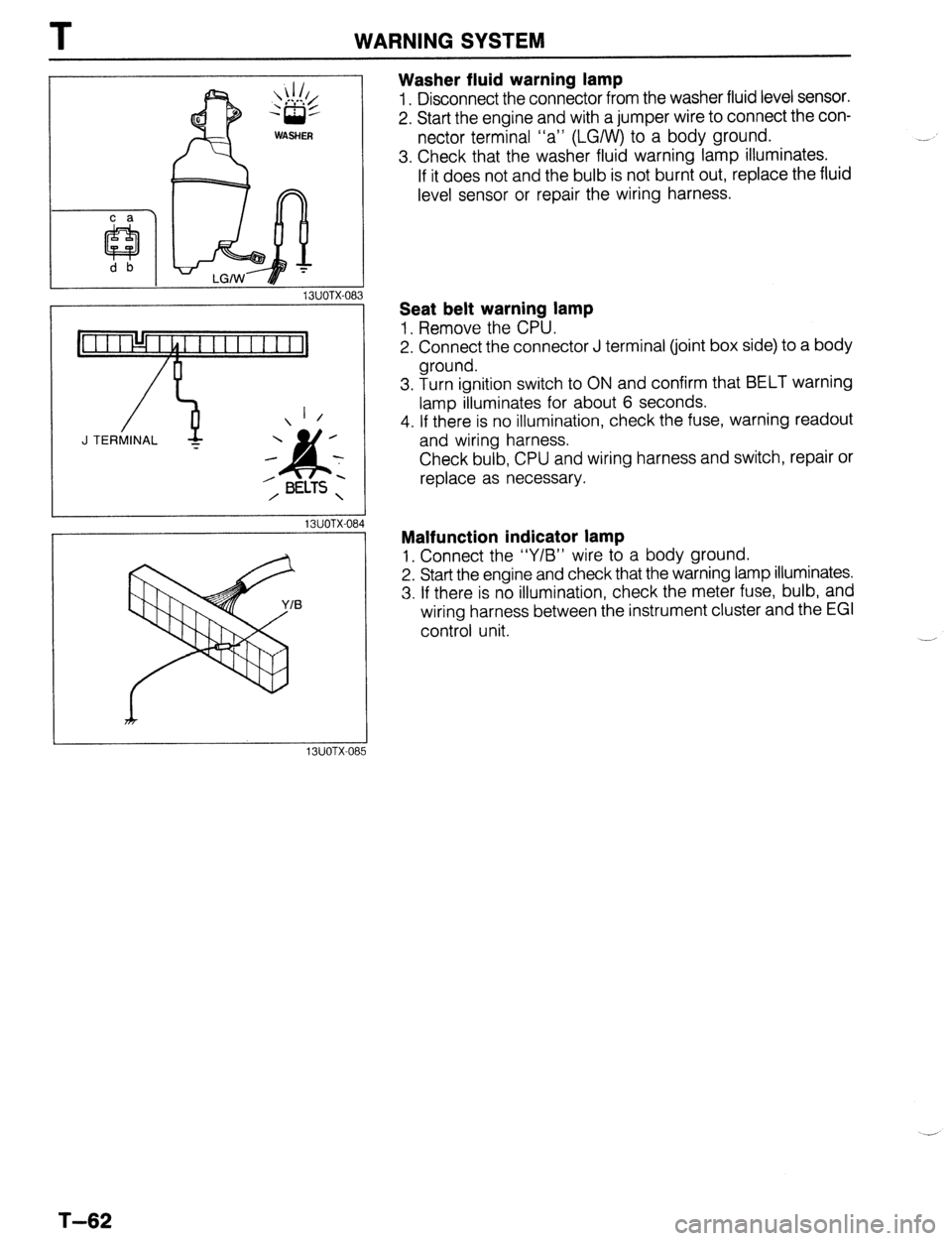
Washer fluid warning lamp
1. Disconnect the connector from the washer fluid level sensor.
2. Start the engine and with a jumper wire to connect the con-
nector terminal “a” (LGIW) to a body ground.
3. Check that the washer fluid warning lamp illuminates.
If it does not and the bulb is not burnt out, replace the fluid
level sensor or repair the wiring harness.
13UOTX-08
_-
1 /
J TERMINAL -
13UOTX-08
13UOTX-08
Seat belt warning lamp
1, Remove the CPU.
2. Connect the connector J terminal (joint box side) to a body
ground.
3. Turn ignition switch to ON and confirm that BELT warning
lamp illuminates for about 6 seconds.
4. If there is no illumination, check the fuse, warning readout
and wiring harness.
Check bulb, CPU and wiring harness and switch, repair or
replace as necessary.
Malfunction indicator lamp
1, Connect the “Y/B” wire to a body ground.
2. Start the engine and check that the warning lamp illuminates.
3. If there is no illumination, check the meter fuse, bulb, and
wiring harness between the instrument cluster and the EGI
control unit.
T-62
Page 922 of 1164
T INSTRUMENT CLUSTER
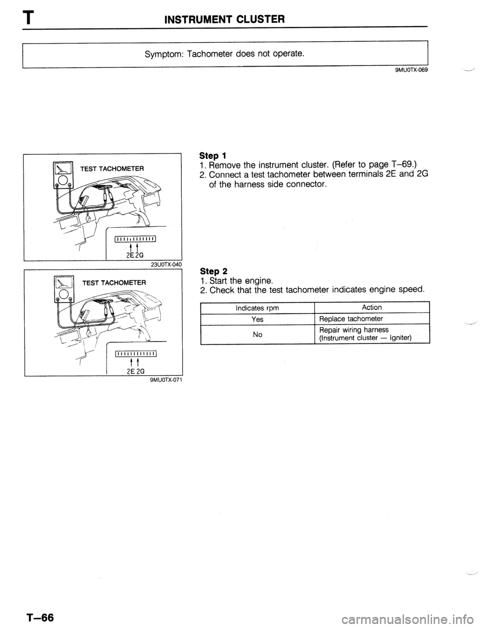
Symptom: Tachometer does not operate.
9MUOTX.069
TEST TACHOMETER
23UOTX-040
2E 2G SMUOTX-01
Step 1
1. Remove the instrument cluster. (Refer to page T-69.)
2. Connect a test tachometer between terminals 2E and 2G
of the harness side connector.
Step 2
1. Start the engine.
2. Check that the test tachometer indicates engine speed.
Indicates rpm
Yes
No Action
Replace tachometer
Repair wiring harness
(Instrument cluster - Igniter)
T-66
Page 927 of 1164
INSTRUMENT CLUSTER T
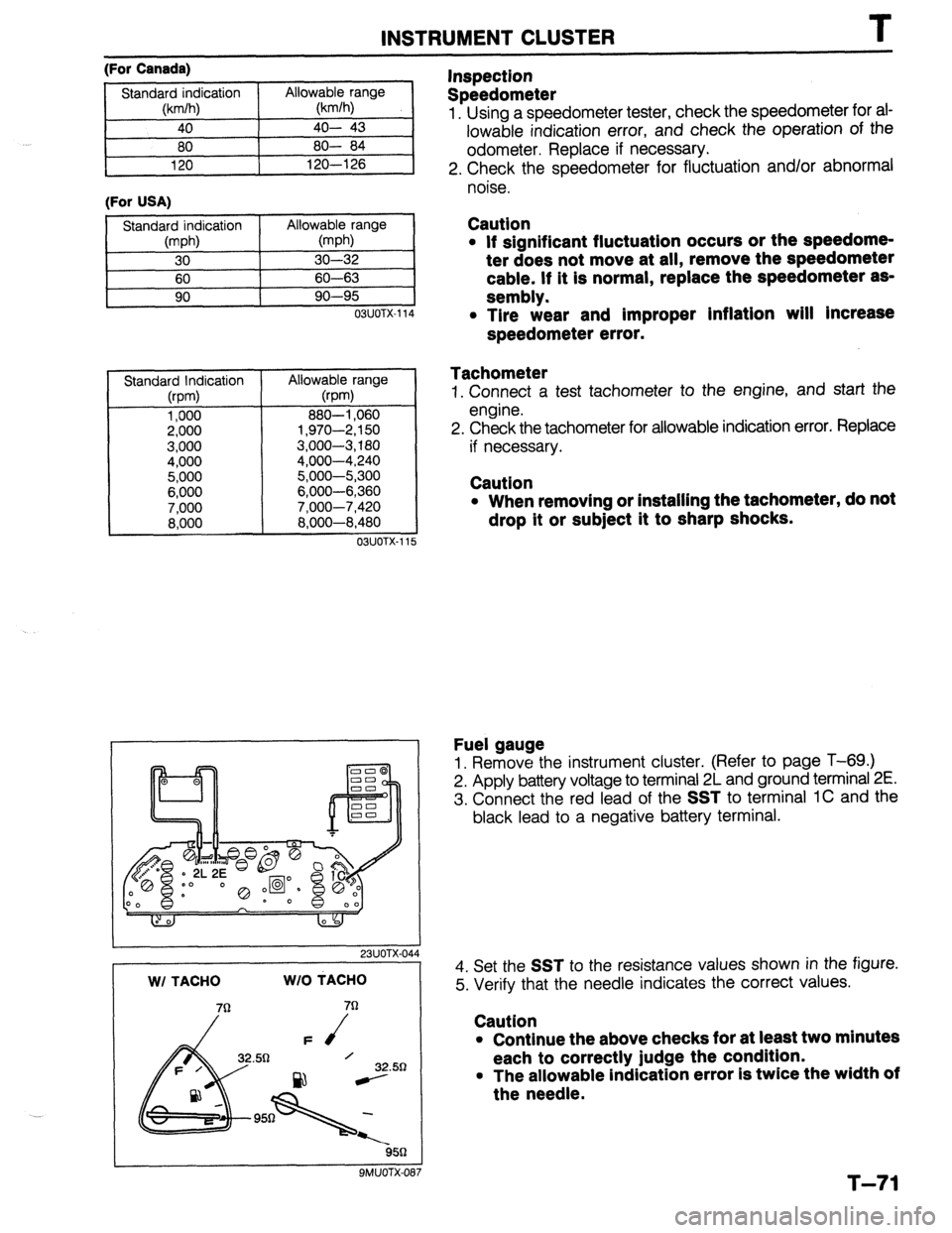
(For Canada)
(For USA)
11
OSUOTX-114
Standard Indication
(rpm)
1,000
2,000
3,000
4,000
5,000
6,000
7,000
8,000 Allowable range
@pm)
880-l ,060
1,970-2,150
3,000-3,180
4,000-4,240
5,000-5,300
6,000-6,360
7.000-7.420
8:600-8:480
03UOTX-11 5
I 23UOTX-044 WI TACHO WIO MACHO
32.50
ssn
9MUOTX-087
Inspection
Speedometer
1. Using a speedometer tester, check the speedometer for ai-
lowable indication error, and check the operation of the
odometer. Replace if necessary.
2. Check the speedometer for fluctuation and/or abnormal
noise.
Caution
l If significant fluctuation occurs or the speedome-
ter does not move at all, remove the speedometer
cable. If it is normal, replace the speedometer as-
sembly.
l Tire wear and improper inflation will Increase
speedometer error.
Tachometer
1. Connect a test tachometer to the engine, and start the
engine.
2. Check the tachometer for allowable indication error. Replace
if necessary.
Caution
l When removing or installing the tachometer, do not
drop it or subject it to sharp shocks.
Fuel gauge
1. Remove the instrument cluster. (Refer to page T-69.)
2. Apply battery voltage to terminal 2L and ground terminal 2E.
3. Connect the red lead of the
SST to terminal 1C and the
black lead to a negative battery terminal.
4. Set the
SST to the resistance values shown in the figure.
5. Verify that the needle indicates the correct values.
Caution
l Continue the above checks for at least two minutes
each to correctly judge the condition.
l The allowable indication error is twice the width of
the needle.
T-71
Page 941 of 1164
CRUISE CONTROL SYSTEM T
Cont’d
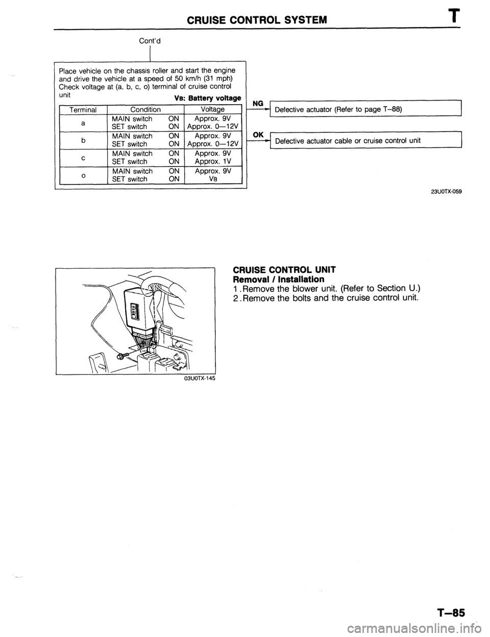
Place vehicle on the chassis roller and start the engine
and drive the vehicle at a speed of 50 km/h (31 mph)
Check voltage at (a, b, c, o) terminal of cruise control
unit Va: Battery voltage
Terminal Condition Voltage
MAIN switch ON
a Approx. 9V
SET switch
ON Approx. 0-12V
b MAIN switch ON Approx. 9V
SET switch ON Approx. 0-12V
MAIN switch ON
C Approx. 9V
SET switch ON
Approx. 1V
0 MAIN switch
Approx. 9V
SET switch Va
OBUOTX
Defective actuator (Refer to page T-88) I
Defective actuator cable or cruise control unit
23UOTX-059
CRUISE CONTROL UNIT
Removal / Installation
1 .Remove the blower unit. (Refer to Section U.)
2. Remove the bolts and the cruise control unit.
T-85
Page 964 of 1164
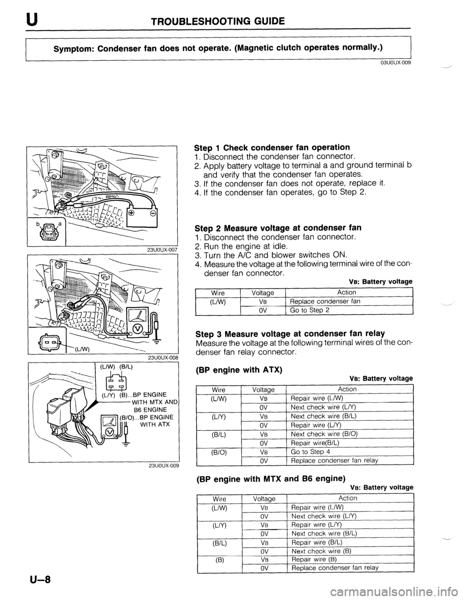
TROUBLESHOOTING GUIDE
Symptom: Condenser fan does not operate. (Magnetic clutch operates normally.)
03uoux-009
I 23UOlJX-007
WITH
MTX AND
fi==Tl (B/O)...BP ENGINE
-’ WITH ATX
Step 1 Check condenser fan operation
1. Disconnect the condenser fan connector.
2. Apply battery voltage to terminal a and ground terminal b
and verify that the condenser fan operates.
3. If the condenser fan does not operate, replace it.
4. If the condenser fan operates, go to Step 2.
Step 2 Measure voltage at condenser fan
1. Disconnect the condenser fan connector.
2. Run the engine at idle.
3. Turn the A/C and blower switches ON.
4. Measure the voltage at the following terminal wire of the con-
denser fan connector.
VB: Battery voltage
Wire
WV Voltage
VB
ov Action -
Replace condenser fan
Go to Step 2
Step 3 Measure voltage at condenser fan relay
Measure the voltage at the following terminal wires of the con-
denser fan relay connector.
(BP engine with ATX)
VB: Battery voltage
(BP engine with MTX and 66 engine)
Ve: Battery voltage
Wire Voltage Action
o-/W) VI3 Repair wire (L/W)
ov Next check wire (L/Y)
VY) VB Repair wire (L/Y)
ov Next check wire (B/L)
VW VB Repair wire (B/L)
ov Next check wire (B)
03 Va Repair wire (B)
ov Replace condenser fan relay ,
U-8
Page 965 of 1164
TROUBLESHOOTING GUIDE U
‘)
IO
1
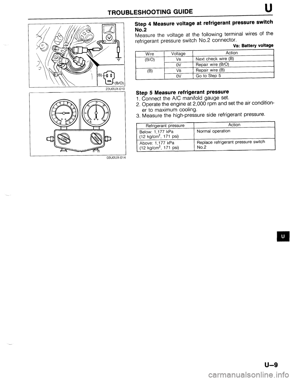
Step 4 Measure voltage at refrigerant pressure switch
No.2
Measure the voltage at the following terminal wires of the
refrigerant pressure switch No.2 connector. VB: Battery voltage
Wire
WO)
(‘3 Voltage Action
VB Next check wire (B)
ov Repair wire (B/O)
V0 Repair wire (B)
ov Go to Step 5
Step 5 Measure refrigerant pressure
1. Connect the A/C manifold gauge set.
2. Operate the engine at 2,000 rpm and set the air condition-
er to maximum cooling.
3. Measure the high-pressure side refrigerant pressure.
Refrigerant pressure
Below: 1 ,177 kPa
(12 kg/cm*, 171 psi)
Above: 1 ,177 kPa
(12 kg/cm’. 171 psi) Action
Normal operation
Replace refrigerant pressure switch No.2
u-9