check engine MAZDA PROTEGE 1992 Workshop Manual
[x] Cancel search | Manufacturer: MAZDA, Model Year: 1992, Model line: PROTEGE, Model: MAZDA PROTEGE 1992Pages: 1164, PDF Size: 81.9 MB
Page 966 of 1164

U TROUBLESHOOTING GUIDE
Symptom: Magnetic clutch does not operate. (Condenser fan operates normally.)
03uoux-015
_-I
I 23UOUX-011
Step 1 Measure voltage at compressor connector
1. Run the engine at idle.
2. Turn A/C and the blower switches ON.
3. Measure the voltage at the following terminal wire of the
compressor connector.
VB: Battery voltage
Wire
P/W Voltage
V0
ov Action
Go to Step 2
Go to Step 5
Step 2 Measure voltage at magnetic clutch connector
Measure the voltage at the following terminal wire of the mag-
netic clutch connector. Ve: Battery voltage
--
Wire Voltage Action
(B)
VB Go to Step 3
ov
t Go to Step 4
Step 3 Check magnetic clutch
1, Disconnect the magnetic clutch connector.
2. Check for continuity between the magnetic clutch and a
body ground.
Continuity
Yes
No Action
Adjust magnetic clutch clearance or
check for compressor internal trouble
Check ground wire
If ground wire OK, replace magnetic
clutch
Step 4 Check thermal protector
1. Turn the air conditioner OFF for about 10 minutes.
2. After 10 minutes, check for continuity of the thermal pro-
tector.
Continuity Action
Yes Normal operation
No Replace thermal protector .._
Page 968 of 1164

TROUBLESHOOTING GUIDE
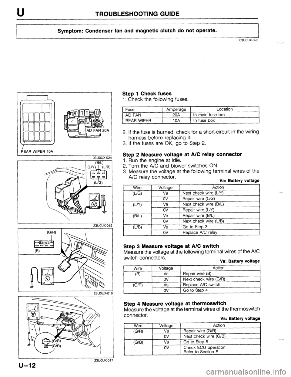
Symptom: Condenser fan and magnetic clutch do not operate.
03uoux-023
r
3EAR WIPER 10A OA
L
03uoux-02.
I
1 Step 1 Check fuses
1. Check the following fuses.
Fuse Amperage Location
AD FAN 20A In main fuse box
REAR WIPER 10A In fuse box
2. If the fuse is burned, check for a short-circuit in the wiring
harness before replacing it.
3. If the fuses are OK, go to Step 2.
I
23uoux-011
Step 2 Measure voltage at A/C relay connector
1. Run the engine at idle.
2. Turn the A/C and blower switches ON.
3. Measure the voltage at the following terminal wires of the
A/C relay connector. VEX Battery voltage
,
Wire
0-Q
W) Voltage Action
VB Next check wire (L/Y)
ov Repair wire (L/G)
V0 Next check wire (B/L)
ov
VB
ov
VB
ov Repair wire (L/Y)
Repair wire (B/L)
Next check wire (LIB)
Go to Step 3
Replace A/C relay
Step 3 Measure voltage at A/C switch
Measure the voltage at the following terminal wires of the A/C
switch connectors.
VB: Battery voltage
Step 4 Measure voltage at thermoswitch
Measure the voltage at the terminal wires of the thermoswitch
connector.
VB: Battery voltage
Wire
(G/R)
WB)
Voltage
VB
ov
VB
OV
Action
Repair wire (G/R)
Next check wire (G/B)
Go to Step 5
Check ECU ooeration
1 -. [ Refer to Secti6n F
u-12
Page 969 of 1164

TROUBLESHOOTING GUIDE U
Step 5 Check thermoswitch
1. Turn OFF the A/C switch and set the blower switch to the
fourth position to operate the blower fan for a few minutes.
2. After a few minutes, turn OFF the blower switch and stop
the engine.
3. Disconnect the thermoswitch connector and check for con-
tinuity of the thermoswitch.
Terminals Continuity Action
a-b Yes Normal operation
No Redace thermoswitch
u-13
Page 970 of 1164

TROUBLESHOOTING GUIDE
I I
Symptom: Insufficient cooling.
No cooling.
Intermittent cooling.
I I
03uoux-110
SIGHT GLASS
o5uoux-020
Step 1 Checking refrigerant charge
1. Run the engine at a fast idle.
2. Operate the air conditioner at maximum cooling for a few
minutes.
3. Observe the sight glass to determine the amount of refriger-
ant and the related action as shown below.
Item Symptom Amount of refrigerant Action
1 Bubbles present in sight glass Insufficient refrigerant Check refrigerant pressure;
go to Step 2
2 No bubbles present in sight glass Too much or proper amount of Turn air conditioner OFF, and
refrigerant watch bubbles (Refer to Items 3
and 4)
__
3 Immediately after air conditioner turned Too much refrigerant Check refrigerant pressure;
OFF, refrigerant in sight glass stays clear go to Step 2
4 When air conditioner turned OFF, refrigerant
Proper amount of refrigerant Refrigerant amount normal
foams, and then sight glass becomes clear
9MUOUX-073
23UOUX-05i
Step 2 Checking refrigerant pressure
1. Connect the A/C manifold gauge set.
2. Operate the engine at 2,000 rpm and set the air condition-
er to maximum cooling.
3. Measure the low- and high-pressure sides.
(Refer to page U-37.)
Normal pressure
Low-pressure side:
147-294 kPa (1 J-3.0 kg/cm*, 21-43 psi)
High-pressure side:
1,177-1,619 kPa (12.0-16.5 kg/cm2, 171-235 psi)
4. If the pressures are not as specified, refer to the chart on
the next page and check the system.
u-14
Page 975 of 1164

TROUBLESHOOTING GUIDE U
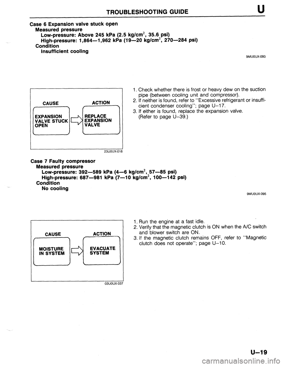
Case 6 Expansion valve stuck open
Measured pressure
Low-pressure: Above 245 kPa (2.5 kg/cm2, 35.6 psi)
High-pressure: 1,864-l ,962 kPa (19-20 kg/cm2, 270-284 psi)
Condition
Insufficient cooling
QMUOUX-093
23UOUX-01’
1. Check whether there is frost or heavy dew on the suction
pipe (between cooling unit and compressor).
2. If neither is found, refer to “Excessive refrigerant or insuffi-
cient condenser cooling”; page U-17.
3. If either is found, replace the expansion valve.
(Refer to page U-39.)
Case 7 Faulty compressor
Measured pressure
Low-pressure: 392-589 kPa (4-6 kg/cm2, 57-85 psi)
High-pressure: 687-981 kPa (7-10 kg/cm2, loo-142 psi)
Condition
No cooling
MOISTURE EVACUATE
IN SYSTEM SYSTEM
I
9MUOUX-095
1. Run the engine at a fast idle.
2. Verify that the magnetic clutch is ON when the A/C switch
and blower switch are ON.
3. If the magnetic clutch remains OFF, refer to “Magnetic
clutch does not operate”; page U-10.
u-19
Page 990 of 1164

ENGINE sro~i32 U
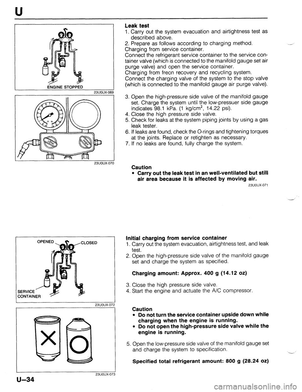
Leak test
1. Carry out the system evacuation and airtightness test as
described above.
2. Prepare as follows according to charging method.
Charging from service container.
Connect the refrigerant service container to the service con-
tainer valve (which is connected to the manifold gauge set air
purge valve) and open the service container.
Charging from freon recovery and recycling system.
Connect the charging valve of the system to the stop valve
(which is connected to the manifold gauge air purge valve).
23UOUX-06
23UOUX-070
I 23UOUX-072
I
80 x 0
23UOUX-07
u-34
3
3. Open the high-pressure side valve of the manifold gauge
set. Charge the system until the low-pressuer side gauge
indicates 98.1 kPa. (1 kg/cm*, 14.22 psi).
4. Close the high pressure side valve.
5. Check for leaks at the system piping joints by using a gas
leak tester.
6. If leaks are found, check the O-rings and tightening torques
at the joints. Replace or retighten as necessary.
7. If no leaks are found, fully charge the system.
Caution
l Carry out the leak test in an well-ventilated but still
air area because it is affected by moving air.
23UOUX-071
Initial charging from service container
1. Carry out the system evacuation, airtightness test, and leak
test.
2. Open the high-pressure side valve of the manifold gauge
set and charge the system as specified.
Charging amount: Approx. 400 g (14.12 oz)
3. Close the high pressure side valve.
4. Start the engine and actuate the A/C compressor.
Caution
l Do not turn the service container upside down while
charging when the engine is running.
l Do not open the high-pressure side valve while the
engine is running.
5. Open the low-pressure side valve of the manifold gauge set
and charge the system to specification.
Specified total refrigerant amount: 800 g (28.24 oz) -.
Page 993 of 1164

AIR CONDITIONER U / ,
9MUOUX-13
SIGHT GLASS
Checking refrigerant charge
1. Run the engine at a fast idle.
2. Operate the air conditioner at maximum cooling for a few
minutes.
3. Determine the amount of refrigerant as shown below by ob-
serving the sight glass.
Item Symptom Amount of refrigerant Action
I Bubbles present in sight glass Insufficient refrigerant Check refrigerant pressure
2 No bubbles present in sight glass Too much or proper amount of Turn air conditioner OFF, and
refrigerant watch bubbles (Refer to Items 3
and 4)
3 Immediately after air conditioner turned Too much refrigerant Check refrigerant pressure
OFF, refrigerant in sight glass stays clear
4 When air conditioner turned OFF, refrigerant Proper amount of refrigerant Refrigerant amount normal
foams, and then sight glass becomes clear
QMUOUX-140
Checking refrigerant pressure
1. Connect the manifold gauge set. (Refer to page U--32.)
2. Operate the engine at 2,000 rpm and set the air condition-
er to maximum cooling.
3. Measure the low- and high-pressure sides.
Normal pressure
Low-pressure side: 147-294 kPa
(1.5-3.0 kg/cm2, 21-43 psi)
High-pressure side: 1 ,I 77-l ,619 kPa
(12.0-l 6.5 kg/cm2, 171-235 psi)
u-37
Page 996 of 1164

U AIR CONDITIONER
OFF
03UOUX-06
03UOUX-06,
03UOUX-06
On-vehicle Inspection
Thermoswitch
1. Remove the glove box.
2. Run the engine at idle.
3. Turn OFF the A/C switch and set the blower switch to the
highest position to operate the blower fan for a few minutes.
4. After a few minutes, turn OFF the blower switch and stop
the engine.
5. Disconnect the thermoswitch connector and check for con-
tinuity between terminals of the switch.
Terminals Continuity
a-b Yes
6. If not as specified, replace the thermoswitch.
Note
l The thermoswitch contacts will be open if the
evaporator temperature is below 0.4 f 0.7OC (32.7
z!z 1.3OF).
Inspection
Thermoswitch
1. Immerse the sensing bulb in a container of ice water.
2. Check continuity between terminals of the switch as
specified.
Terminals
a-b Temperature Continuity
Above 5°C Yes
Below 0% No
3. If not as specified, replace the thermoswitch
Evaporator
1. Check the evaporator fins for blockage. If the fins are
clogged, clean them with compressed air.
Caution
l Never use water to clean the evaporator.
2. Check the fittings for cracks and other damage.
Replace the evaporator if necessary.
u-40
Page 1011 of 1164

AIR CONDITIONER U
REFRIGERANT PRESSURE
2.0 f 0.2 kg/cm* 27 f 2 kg/cm’
4.1 f 0.5 kg/cm* 21 * 4 kg/cm*
03uoux-09
9
23UOUX-050
REFRIGERANT PRESSURE SWITCH No.1
Inspection
1. Turn the ignition switch OFF.
2. Connect the manifold gauge set and measure the high-
pressure side refrigerant pressure.
High-pressure side:
Above 451 kPa (4.6 kg/cm2, 65 psi)
3. If not as specified, check the refrigerant system, referring
to the troubleshooting information on page U-14.
4. If correct, go to the next step.
5. Disconnect the refrigerant pressure switch No.1 connector.
6. Check for continuity of the switch.
Terminals
1 Continuity
a-b
Yes I
7. If not as specified, replace the switch together with cooler
pipe No.2. (Refer to page U-54.)
Note
l If problems occur in the refrigeration system, caus-
ing abnormally high (above 2,649 SL: 196 kPa [27 f
2 kg/cm2, 384 f 28 PSI]) or low (below 196 f 20
kPa [2.0 f 0.2 kg/cm2, 28 & 2.8 psi]) pressures,
refrigerant pressure switch No.1 cuts power to the
magnetic clutch to protect the mechanical compo-
nents. If the pressure recovers to within normal
operating range (below 2,080 f 392 kPa [21 f 4
kg/cm2, 299 f 57 psi] or above 402 f. 49 kPa t4.1
f 0.5 kg/cm2, 58 f 7 psi]), the power is again re-
stored.
REFRIGERANT PRESSURE SWITCH No.2
(BP ENGINE WITH ATX)
Inspection
1. Turn the ignition switch OFF.
2. Connect the manifold gauge set and measure the high-
pressure side refrigerant pressure.
High-pressure side:
below 1,177 kPa (12 kg/cm2, 171 psi)
3. Disconnect the refrigerant pressure switch No.2 connector.
4. Check continuity of the switch.
Terminals
a-b I Continuity
No
5. If not as specified, replace the switch together with cooler
pipe No.2. (Refer to page U-54.)
6. If correct, go to next stop.
u-55
Page 1012 of 1164

AIR CONDITIONER
23UOUX-051
23UOUX-05
23UOUX-05
U-56
Caution
l While testing refrigerant pressure switch No.2, care-
fully note the high-pressure side refrigerant pres-
sure. If the pressure increases above 1,766 kPa (18
kg/cm2, 256 psi), stop the testing. _,
7. Disconnect the condenser fan connector.
8. Run the engine at 2,000 rpm, and operate the air condi-
tioner at maximum cooling position.
9. Check that the refrigerant pressure switch turns on when
the high-pressure side refrigerant pressure increases above
1,570 f 98 kPa (16 f 1 kg/cm2, 228 f 14 psi).
IO. If not as specified, replace the switch together with cooler
pipe No.2. (Refer to page U-54.)
A/C RELAY
Inspection
1. Disconnect the A/C relay connector.
2. Check continuity between terminals of the switch.
Terminals
Tester probe: + 1 Tester probe: -
a b Continuity
Yes
3. If not as specified, replace the relay.
4. If correct, go to the next step.
5. Apply battery voltage to terminal d and ground terminal a.
6. Check for continuity between terminals a and d.
Terminals
a-d Continuity
Yes
7. If not as specified, replace the relay.
CONDENSER FAN RELAY
Inspection
1. Disconnect the condenser fan relay connector.
2. Check continuity between terminals of the relay.
Terminals Continuity
I a-b Yes I
2
I c-d I No I
A 3. If not as specified, replace the relay.
4. If correct, go to the next step.
5. Apply battery voltage to terminal a and ground terminal b.
6. Check for continuity between terminals c and d.
Terminals Continuity
c-d Yes
7. If not as specified, replace the relay.