check engine MAZDA PROTEGE 1992 Owners Manual
[x] Cancel search | Manufacturer: MAZDA, Model Year: 1992, Model line: PROTEGE, Model: MAZDA PROTEGE 1992Pages: 1164, PDF Size: 81.9 MB
Page 397 of 1164

231JOFX-1
FUEL SYSTEM F
INJECTOR
Inspection
Operation check
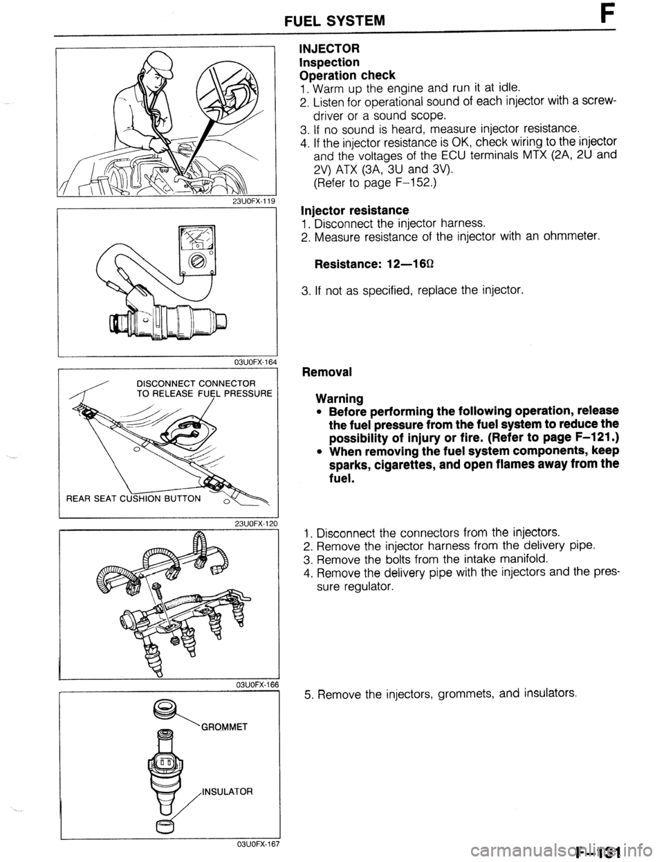
1. Warm up the engine and run it at idle.
2. Listen for operational sound of each injector with a screw-
driver or a sound scope.
3. If no sound is heard, measure injector resistance.
4. If the injector resistance is OK, check wiring to the injector
and the voltages of the ECU terminals MTX (2A, 2U and
2V) ATX (3A, 3U and 3V).
(Refer to page F-152.)
Injector resistance
1. Disconnect the injector harness.
2. Measure resistance of the injector with an ohmmeter.
Resistance: 12-l 6Q
3. If not as specified, replace the injector.
03UOFX-1
DISCONNECT CONNECTOR
TO RELEASE FU5L PRESSUR
REAR SEAT C
23UOFX-1
OBUOFX-
GRQMMET
INSULATOR
c5
OSUOFX-
Removal
Warning
l Before performing the following operation, release
the fuel pressure from the fuel system to reduce the
possibility of injury or fire. (Refer to page F-121 .)
l When removing the fuel system components, keep
sparks, cigarettes, and open flames away from the
fuel.
1. Disconnect the connectors from the injectors.
2. Remove the injector harness from the delivery pipe.
3. Remove the bolts from the intake manifold.
4. Remove the delivery pipe with the injectors and the pres-
sure regulator.
5. Remove the injectors, grommets, and insulators.
F-131
Page 401 of 1164

PRESSUREREGULATORCONTROLSYSTEM F
03UOFX-17
*
03UOFX-14!
OSUOFX-17
SOLENOID VALVE (PRESSURE REGULATOR CONTROL)
Inspection
On-vehicle
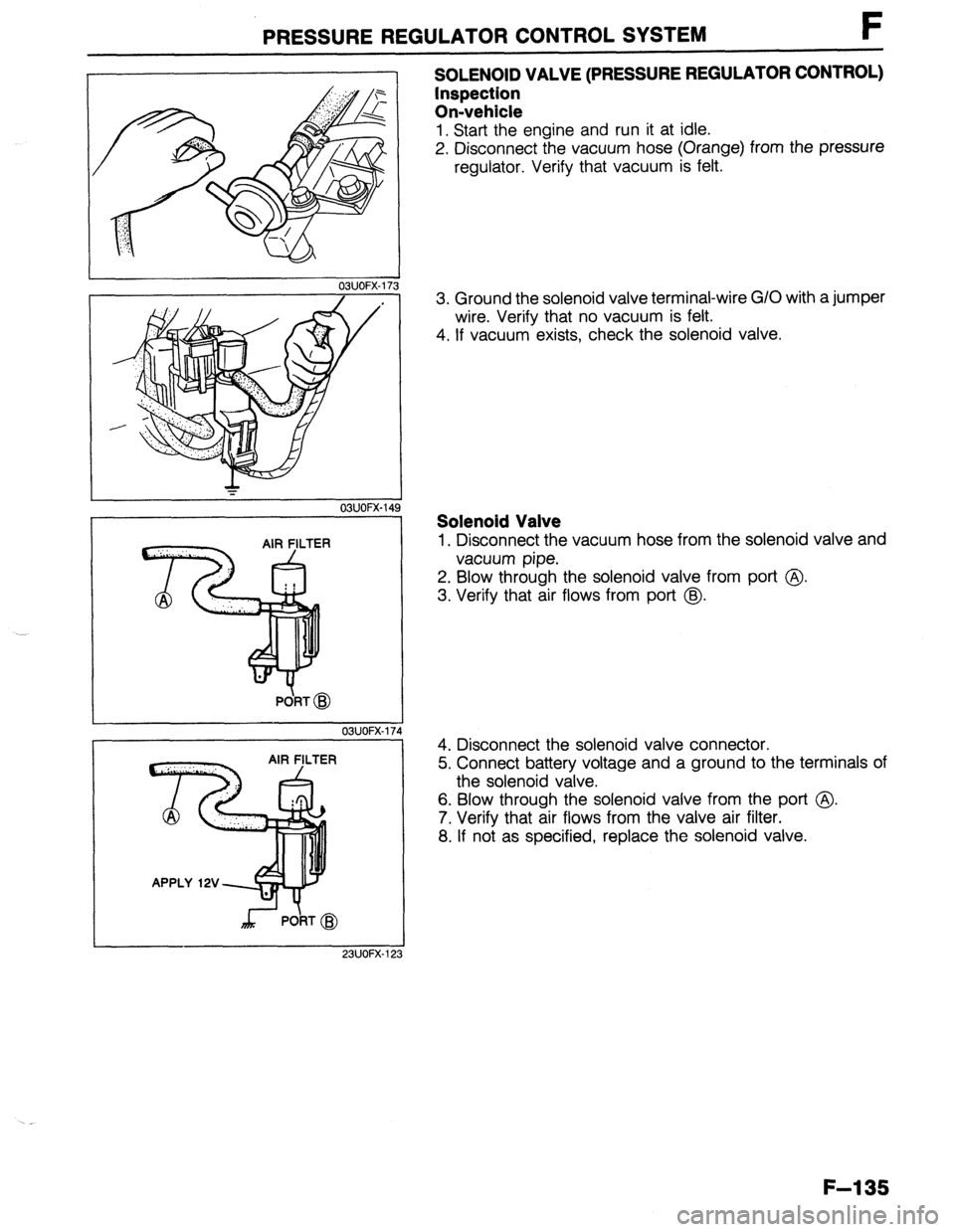
1. Start the engine and run it at idle.
2. Disconnect the vacuum hose (Orange) from the pressure
regulator. Verify that vacuum is felt.
3. Ground the solenoid valve terminal-wire G/O with a jumper
wire. Verify that no vacuum is felt.
4. If vacuum exists, check the solenoid valve.
Solenoid Valve
1. Disconnect the vacuum hose from the solenoid valve and
vacuum pipe.
2. Blow through the solenoid valve from port @
3. Verify that air flows from port @.
4. Disconnect the solenoid valve connector.
5. Connect battery voltage and a ground to the terminals of
the solenoid valve.
6. Blow through the solenoid valve from the port @.
7. Verify that air flows from the valve air filter.
8. If not as specified, replace the solenoid valve.
F-l 35
Page 405 of 1164

EVAPORATIVE EMISSION CONTROL SYSTEM t
EVAPORATIVE EMISSION CONTROL SYSTEM
DESCRIPTION
/ /
ENGINE ENGINE
CONTROL CONTROL - INPUT - INPUT
UNIT UNIT
- -
SOLENOID VALVE SOLENOID VALVE k k / /
CHECK VALVE CHECK VALVE
(TWO-WAY) (TWO-WAY)
CHARCOAL CHARCOAL
CANISTER CANISTER
CHECK-AND-CUTC CHECK-AND-CUTC
VALVE VALVE
SEPARATOR SEPARATOR TO ENGINE TO ENGINE SIGNALS
The evaporative emission control system consists of the separator, the check-and-cut valve, the two-way
check valve, the charcoal canister, the purge control solenoid valve, the engine control unit (ECU), and the
input devices. The amount of evaporative fumes introduced into the engine and burned is controlled by the
solenoid valve to correspond to the engine’s operating conditions. To maintain best engine performance,
the solenoid valve is controlled by the ECU.
Operation
.._ The solenoid valve (purge control) is controlled by duty signals from the ECU to perform purging of the char-
coal canister. Purging is done when these conditions are met:
(1) After warm-up
(2) Driving in gear
(3) Accelerator pedal depressed (idle switch OFF)
(4) Oxygen sensor functioning normally
F-l 39
Page 406 of 1164

F EVAPORATIVE EMISSION CONTROL SYSTEM
03UOFX-17! 3
03UOFX-180
INSTALLATION DIRECTION
F-l 40
I
23UOFX-126
03UOFX-18
OSUOFX-l&
SYSTEM OPERATION
1 Warm up the engine to normal operating temperature and
run it at idle.
2. Disconnect the vacuum hose from the solenoid valve as
shown in the figure, and verify that no vacuum is felt at the
solenoid valve. -.
3. If not as specified, check the solenoid valve.
SOLENOID VALVE (PURGE CONTROL)
Inspection
1. Disconnect the vacuum hoses from the solenoid valve.
2. Verify that no air flows through the valve.
3. Disconnect the solenoid valve connector and supply bat-
tery voltage as shown in the figure.
4. Verify that air flows through the valve.
5. If not as specified, replace the solenoid valve.
SEPARATOR
Inspection
1. Remove the left side trim.
2. Remove the separator.
3. Visually check the separator for damage. Replace it if
necessary.
CHECK VALVE (TWO-WAY)
Inspection
1. Remove the valve.
2. Check the operation of the valve with a vacuum pump.
Apply approx. 37 mmHg (1.46 inHg)
vacuum at port A Airflow
Apply approx. 44 mmHg (1.73 inHg)
vacuum at port B Airflow
Page 408 of 1164

F DECELERATION CONTROL SYSTEM
DECELERATION CONTROL SYSTEM
DESCRIPTION
The dashpot is used to prevent the throttle valve from suddenly closing
03UOFX-185
1
DASHPOT
Inspection
1. Open the throttle valve fully. Push the dashpot rod with a
finger and verify that it goes into the dashpot slowly.
2. Release the rod and check that it comes out quickly.
3. Replace the dashpot if not as specified.
,,
OBUOFX-18
4. Warm up the engine and run it at idle.
5. Connect a tachometer to the diagnosis connector IG-
terminal and increase engine speed to 4,000 rpm.
6. Slowly decrease the engine speed and check that the le-
ver touches the dashpot rod at the specified speed.
Specification:
l B6 ..**.............,....,.............. Approx. 3,000 rpm
l BP SOHC . ..*..................*.... Approx. 2,700 rpm
l BP DOHC . . . . . . . . . . . . . . . . . . . . ...“... Approx. 3,500 rpm
7. If not as specified, loosen the locknut and turn the dashpot
to adjust.
F-l 42
Page 411 of 1164

DECHOKE CONTROL SYSTEM t-
DECHOKE CONTROL SYSTEM
DESCRIPTION
To facilitate starting the engine when the spark plugs become fouled, such as when the engine is flooded,
fuel injection is cut if the throttle valve is held wide open while cranking and the engine coolant temperature
is O°C (32OF) or below. This allows the spark oluas to drv and purges excess fuel from the cylinders.
f-- ECU _
. IGNITION SWITCH (START)
l ENGINE SPEED BELOW 500 rpm ’
l THROTTLE VALVE FULLY OPEN
l ENGINE COOLANT TEMPERATURE ;
BELOW
0% (32°F) I FUEL CUT
OBUOFX-19
I / / ‘ I
SYSTEM OPERATION
1.
2. Check if the engine coolant temperature is below O°C
(32OF).
If the engine coolant temperature is above O°C (32OF), dis-
connect the water thermosensor connector and connect an
approx. 10 kB resistor to the connector.
03UOFX.198 3. Turn the ignition switch to START and verify that the injec-
OBUOFX-19! 3
tor operating sound is heard.
4. Depress the accelerator pedal fully and turn the ignition
switch START. Verify that no injector operating sound is
heard.
F-l 45
Page 413 of 1164

CONTROL SYSTEM F
CONTROLSYSTEM
PREPARATION
SST
49 9200 162
Engine Signal
Monitor
49 HO18 9Al
Self-Diagnosis
Checker
49 GO1 8 904
Sheet For
inspection of
ECU
For
inspection of
oxygen sensor
For
inspection of
ECU 49 GO18 903
Adapter
harness
49 BO19 9AO
System
Selector For
inspection of
ECU
For
inspection of
oxygen sensor
03UOFX-20
F-l 47
Page 415 of 1164

CONTROL SYSTEM F
SMALL TYPE
03UOFX.20:
03UOFX-20
23UOFX-13
TERMINALS
AANDB
c “.w a ,.1/M rrmrrm
_-
03UOFX-201
ENGINE CONTROL UNIT (ECU)
Removal / Installation
1. Remove the side walls (driver’s side and passenger’s side).
(Refer to page S-94.)
2. Remove the bolts and nuts.
3. Disconnect the ECU connectors.
4. Install a
new ECU in the reverse order of removal.
Inspection
1. Disconnect the ECU connectors.
2. Connect the
SSTs (Engine Signal Monitor and Adapt-
er)
to the ECU as shown,
3. Set the SST (Sheet) on the Engine Signal Monitor with
the specified side fancing up as shown.
Note
l MTX...48 PIN
l ATX...84 PIN
4. Measure the voltage at each terminal.
(Refer to pages F-150 to F-167.)
5. If any ECU terminal voltage is incorrect, check the related
input or output devices and wiring. If no problem is found,
replace the ECU. (Refer to above.)
Caution
l Never apply voltage to SST terminals A and B.
F-l 49
Page 434 of 1164

F CONTROL SYSTEM
23UOFX-l! 51
.
r---- - --------1
I
I
i I
I
:,
m7 I
- - -.-
Fc E, Vc Ez 23UOFX-158
WATER THER@OSENSOA
I
03UOFX-21
REPLACE WASHEF
f
OYJOFX-2’
AIRFLOW METER (WITH INTAKE AIR THERMOSENSOR)
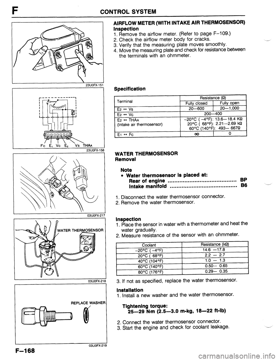
Inspection
1. Remove the airflow meter. (Refer to page F-109.)
2. Check the airflow meter body for cracks.
3. Verify that the measuring plate moves smoothly.
4. Move the measuring plate and check for resistance between
the terminals with an ohmmeter.
Specification
Terminal
E2 * Vs
E2 ++ Vc
E2
* THAA
(Intake air thermosensor)
El +, Fc Resistance (0)
Fully closed 1
Fully open
20-600 1 20-l ,000
200-400
-20% ( -4’=F): 13.6- 18.4 KQ
20% ( 6899 2.21-2.69 kD
60°C (14OOF): 493- 6670
00
0
WATER THERMOSENSOR
Removal
Note
l Water thermosensor Is placed at:
Rear of engine . . . . . . . . . . . . . . . . . . . . . . . . ..*.............. BP
Intake manifold ,.*......,..m...,..,.....*....*......... 86 -’
1. Disconnect the water thermosensor connector.
2. Remove the water thermosensor.
Inspection
1. Place the sensor in water with a thermometer and heat the
water gradually.
2. Measure resistance of the sensor with an ohmmeter.
3. If not as specified, replace the water thermosensor.
lnstallatlon
1. Install a new washer and the water thermosensor.
Tlghtening torque:
25-29 N.m (2.5-3.0 m-kg,
18-22 ft-lb)
2. Connect the water thermosensor connector.
3. Start the engine and check for coolant leakage.
F-l 68
Page 437 of 1164

CONTROL SYSTEM F
03UOFX-227
03UOFX-22:
03UOFX-22!
*
03UOFX-231
I
SELF-W CtECXER
WOFX-15
Replacement
1. Disconnect the throttle sensor connector.
2. Remove the throttle sensor mounting screws.
3. Remove the throttle sensor.
4. Install in the reverse order of removal.
Tightening torque:
1.6-2.4 N-m (16-24 cm-kg, 14-21 in-lb)
OXYGEN SENSOR
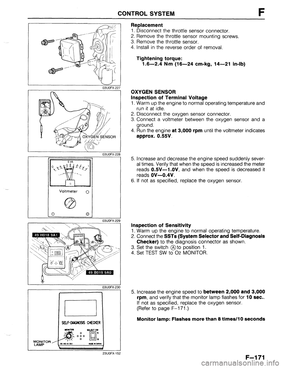
Inspection of Terminal Voltage
1. Warm up the engine to normal operating temperature and
run it at idle.
2. Disconnect the oxygen sensor connector.
3. Connect a voltmeter between the oxygen sensor and a
ground.
4. Run the engine
at 3,000 rpm until the voltmeter indicates
approx. 0.55V.
5. Increase and decrease the engine speed suddenly sever-
al times. Verify that when the speed is increased the meter
reads
OSV-1 .OV, and when the speed is decreased it
reads
OV-0.4V.
6. If not as specified, replace the oxygen sensor.
Inspection of Sensitivity
1. Warm up the engine to normal operating temperature.
2. Connect the
SSTs (System Selector and Self-Diagnosis
Checker)
to the diagnosis connector as shown.
3. Set the switch @to position 1.
4. Set TEST SW to 02 MONITOR.
5. Increase the engine speed to
between 2,000 and 3,000
rpm,
and verify that the monitor lamp flashes for 10 sec..
If not as specified, replace the oxygen sensor.
(Refer to page F-l 71.)
Monitor lamp: Flashes more than 8 times/l 0 seconds
F-l 71