check engine MAZDA PROTEGE 1992 Manual Online
[x] Cancel search | Manufacturer: MAZDA, Model Year: 1992, Model line: PROTEGE, Model: MAZDA PROTEGE 1992Pages: 1164, PDF Size: 81.9 MB
Page 350 of 1164

F SELF-DIAGNOSIS FUNCTION
Troubleshooting
If a service code number is shown on the SST, check for the cause by using the chart related to the code
number shown.
Service code number
CODE LOCATION OF
NO.
MALFUNCTION OUTPUT SIGNAL PATTERN
SELF-DIAGNOSIS FAIL-SAFE
02
Ne-signal
:E nl-u No Ne-signal
-
03 G-signal
(DOHC) No G-signal Cancels 2-group
injection
06* Vehicle speed
sensor ON
OFF No input signal from Shifting performed
vehicle speed normally
sensor
08 Airflow meter ON
OFF Open or short circuit Basic fuel injection
amount fixed as for two
driving modes
(1) Idle switch ON
(2) Idle switch OFF
09 Water
thermosensor ON
OFF Maintains constant 20%
(68OF) command
10 Intake air
thermosensor Maintains constant 20°C
(68OF) command
12
Throttle sensor
“,E l--uL-l Throttle opening judged
as full stroke lockup not
provided
Atmospheric ON Maintains constant
14 pressure sensor command of sea level
(in ECU)
OFF pressure
15 Oxygen sensor
(inactivation) ON
OFF Sensor output
continues less than
0.55V 95 sec. after
engine starts
(1500 rpm) Cancels engine feedback
operation
Oxygen sensor ON Sensor output Cancels engine feedback
17
(Inversion) continues uncharged operatron
OFF 50 sec. after engine
exceeds 1500 rpm
Solenoid valve ON
25 (pressure
regulator)
OFF u 1 nnluln Open or short crrcurt
“If the marked code numbers appeor, refer to Section K
F-84
Page 366 of 1164

SELF-DIAGNOSIS FUNCTION
:ODE No. 17 (Oxygen sensor-lnvarsion)
r t
INSPECTION
Check if same Code No. is present after per-
forming after-repair procedure CT- page F-704
Check monitor lamp of Self-Diagnosis Checker il-
luminate at idle after warming-up engine and
running it at 2,500-3,000 rpm
for 3 minutes
Check for correct fuel line pressure at idle CT page F-129
Fuel line pressure;
265-314 kPa (2.7-3.2 kg/cm2, 38-46 psi)
{Vacuum hose to pressure regulator
disconnected)
4 Check injectors for fuel teakage c3 page F-132
5
Disconnect each high-tension lead at idle and
check if engine speed decreases equally at each
cylinder
Circuit Oiagram
MTX
I ACTION
Yes 1 Go to next step NO
Check oxygen sensor circuit for poor
connection
r3 If OK, perform troubleshooting
Code No.15
a
If not OK, repair or replace con-
nector u page F-98
Yes Go to next step Note
l A/F mixture rich
No
I Go to Step 5 Note
l A/F mixture is lean or misfire
occurring
Yes
I Go to next step No High pressure
Check if fuel return hose is ciogged or
restricted
+ If OK, replace pressure regulator CT page F-130
c3 If not OK, repair or replace
Yes Replace injector
No Check if water thermosensor is OK
ti if OK, Go to Step 11
c3 If not OK, replace water thermo-
sensor c7 page F-168
CT page F-168
Yes
Go to next step No
Go to Step 8
23UOFX-07
OXYGEN SENSOR
I
R/L
ECU
----------h--M
23UOFX-074
F-l 00
Page 368 of 1164

SELF-DIAGNOSIS FUNCTION
:ODE No. 1 25 (SOLENOID VALVE - PRESSUREREGULATORCONTROL)-BPENGINE
r (
TEP
1
-
2
-
3 I
INSPECTION
Disconnect connector from ECU and check if
battery voltage exists at ECU terminal 2T (MTX)
3M (ATX) wire (G/O) with ignition switch ON
In same condition as Step 1, check if battery
voltage exists at solenoid valve connector
terminal-wire (G/O) ACTION
Yes Check ECU terminal connector for poor -
connection
* If OK, replace ECU CT page F-149
+
If not OK, repair or replace connector
No Go to next step
Yes Repair or replace wire (G/O)
No Go to next step
Check if solenoid valve is OK Yes Check for short or open circuit in wiring
w page F-135 from main relay (FUEL INJ relay) to
solenoid valve
No Replace solenoid valve
I I I
23UOFX-077
:ODE No. 26 (SOLENOID VALVE - PURGE CONTROL)
STEP INSPECTION
Disconnect connector from ECU and check if
battery voltage exists at ECU terminal 2X (MTX)
20 (ATX) wire harness (W/L) with ignition switch
ON Yes
No
In same condition as Step 1, check if battery
Yes
voltage exists at solenoid valve connector
terminal-wire (W/L)
No
Check if solenoid valve is OK
Yes
w page F-140
t- No
--
4 ACTION
Check ECU terminal connector for poor
connection
ti If OK, replace ECU c;p page F-149
e
If not OK, repair or replace connector
Go to next step
Repair or replace wire harness (W/L)
Go to next step
Check for short or open circuit in wiring
from main relay (FUEL INJ relay) to
Circuit Diagram
MTX
I-
FROM
BATTERY
FROM
23UOFX-07 9
F-l 02
Page 370 of 1164

F SELF-DIAGNOSIS FUNCTION
23UOFX-08: 3
03UOFX.086
i:a pj
MONITOR
SELECT El
03UOFX-:6
7
I
7
After-repair Procedure
1. Cancel the memory of malfunctions by disconnecting the
negative battery cable for
at least 20 seconds. Reconnect
the negative battery cable.
2. Connect the
SST (System Selector) to the diagnosis con-
nector.
3. Set the switch @to position 1.
4. Set TEST SW to SELF-TEST.
5. Connect the
SST (Self-Diagnosis Checker) to the System
Selector and a ground.
6. Set the select switch of the Self-Diagnosis Checker to posi-
tion A.
7. Turn the ignition switch ON.
8. Start and warm up the engine, then run it at
2,000 rpm for
three minutes.
9. Verity that no code numbers are displayed.
F-l 04
Page 371 of 1164

SELF-DIAGNOSIS FUNCTION F
SWITCH MONITOR FUNCTION
Individual switches can be inspected by the SST (Self-Diagnosis checker).
Note
l The TEN terminal of the diagnosis connector must be grounded and the ignition switch ON
(engine stopped).
l If either of the switches remain activated, the monitor lamp will be illuminated.
ECU
NEUTRAL SWITCH (MTX)
CLUTCH SWITCH (MTX)
=d-’ 1
BATTERY
INHIBITOR SWITCH (ATX)
STOPLIGHT SWITCH (MTX)
HEADLIGHT SWITCH MONITER LAMP
REAR WINDOW (SELF-DIAGNOSIS CHECKER)
DEFROSTER SWITCH
AIC SWITCH
BLOWER SWITCH
THROTTLE SENSOR asp-
- _
COOLING FAN SWITCH
03UOFX
Switch
Clutch switch
Neutral switch (MW
(M-W Self-Diagnosis Checker (Monitor lamp)
Light ON Light OFF Pedal released Pedal depressed
In gear Neutral Remark In gear
Clutch pedal released
Inhibitor switch
(ATX) L, S, D or R range
N or P range -
Throttle sensor Pedal depressed (Not fully) Pedal released/fully depressed -
Stoplight switch
Pedal depressed Pedal released -
Headlight switch
ON
OFF Headlights/parking lights: ON
Blower switch
ON
OFF Blower switch at 2nd or
above position
AIC switch
ON OFF Fan speed control at 1st po-
sition
Rear window defroster
switch ON
OFF -
Water thermoswitch Fan operating Fan not operating -
23UOFX-084
F-l 05
Page 372 of 1164
SELF-DIAGNOSIS FUNCTION
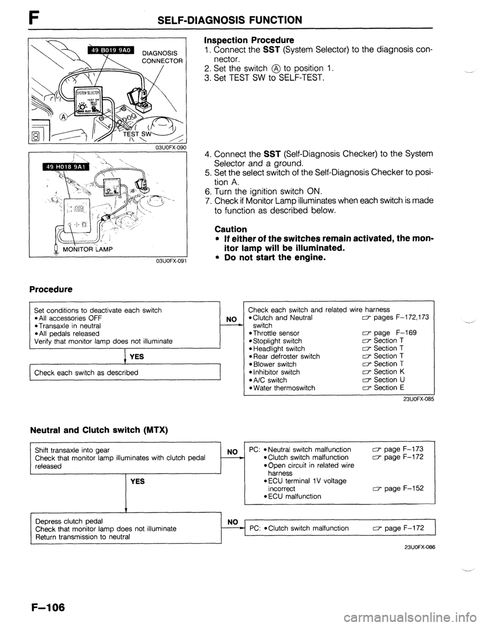
Inspection Procedure
1. Connect the SST (System Selector) to the diagnosis con-
nector.
2. Set the switch @ to position 1.
3. Set TEST SW to SELF-TEST.
03UOFX.090
MONITOR LAMP
T
03UOFX-091
Procedure
4. Connect the SST (Self-Diagnosis Checker) to the System
Selector and a ground.
5. Set the select switch of the Self-Diagnosis Checker to posi-
tion A.
6. Turn the ignition switch ON.
7. Check if Monitor Lamp illuminates when each switch is made
to function as described below.
Caution
* If either of the switches remain activated, the mon-
itor lamp will be illuminated.
l Do not start the engine.
I
I Set conditions to deactivate each switch l All accessories OFF l Transaxle in neutral l All pedals released NO
-
Verify that monitor lamp does not illuminate
YES
Check each switch as described Check each switch and related wire harness
*Clutch and Neutral CT- pages F-l 72,173
switch
*Throttle sensor w page F-169 l Stoplight switch c7 Section T l Headlight switch c7 Section T l Rear defroster switch T;P Section T l Blower switch [r+ Section T
l Inhibitor switch a Section K l A/C switch 0 Section U l Water thermoswitch c7 Section E
23UOFX-OS!
Neutral and Clutch switch (MTX)
Shift transaxle into gear
Check that monitor lamp illuminates with clutch pedal
released
YES NO PC: l Neutral switch malfunction a page F-173 l Clutch switch malfunction w page F-172
*Open circuit in related wire
harness
l ECU terminal 1 V voltage
incorrect w page F-152
l ECU malfunction
Depress clutch pedal
Check that monitor lamp does not illuminate
Return transmission to neutral PC:
*Clutch switch malfunction w page F-172
23UOFX-088
F-l 06
Page 379 of 1164
INTAKE AIR SYSTEM F
I 23UOFX-096
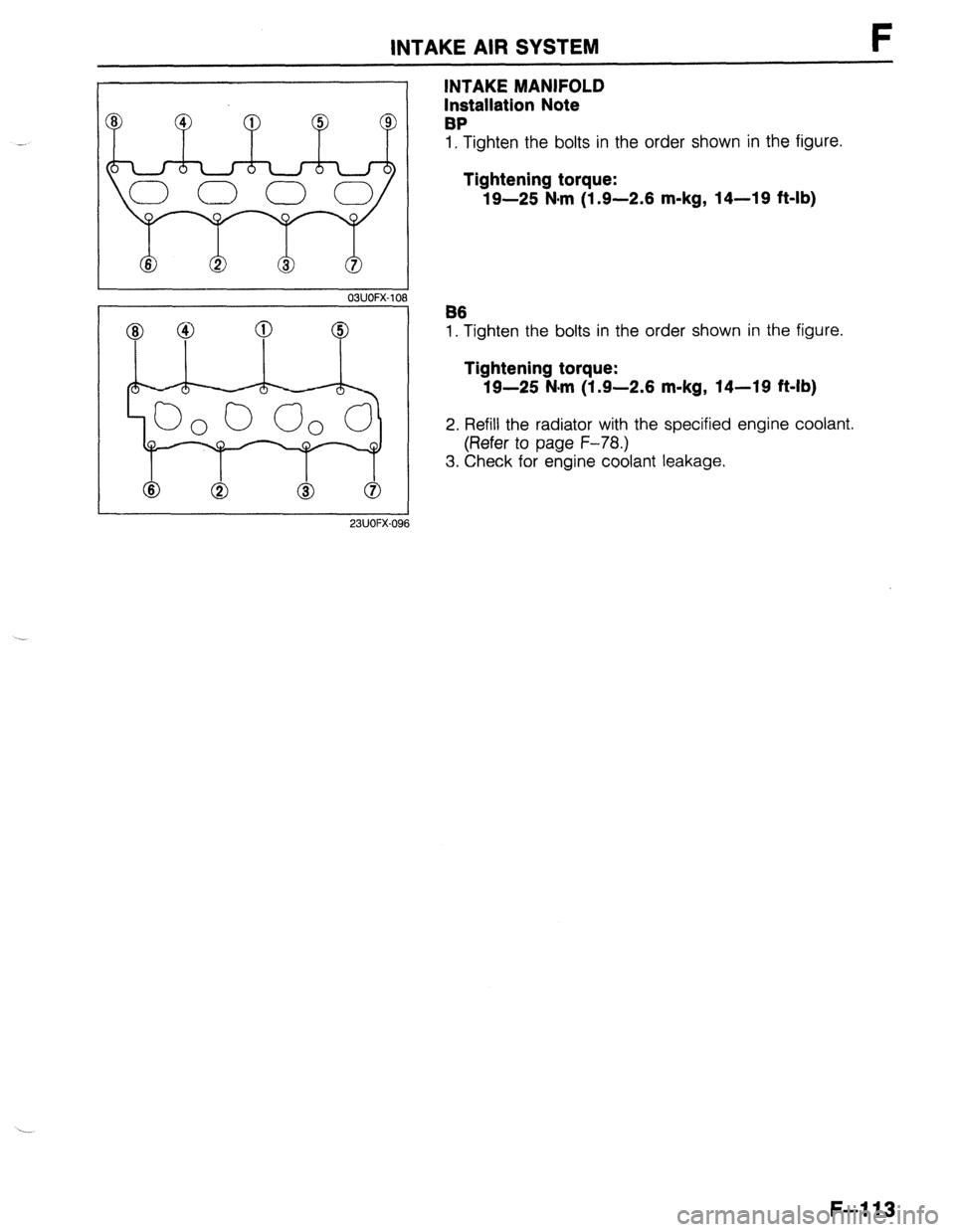
INTAKE MANIFOLD
Installation Note
BP
1, Tighten the bolts in the order shown in the figure.
Tightening torque:
19-25 N-m (1.9-2.6 m-kg, 14-19 ft-lb)
B6
1. Tighten the bolts in the order shown in the figure.
Tightening torque:
19-25 N-m (1.9-2.6 m-kg, 14-19 ft-lb)
2. Refill the radiator with the specified engine coolant.
(Refer to page F-78.)
3. Check for engine coolant leakage.
F-113
Page 382 of 1164
F IDLE SPEED CONTROL (ISC) SYSTEM
PREPARATION
SST
OBUOFX-113
OSUOFX-I 14
I
23UOFX-095
J 03UOFX-1 lf
23UOFX-101
F-116
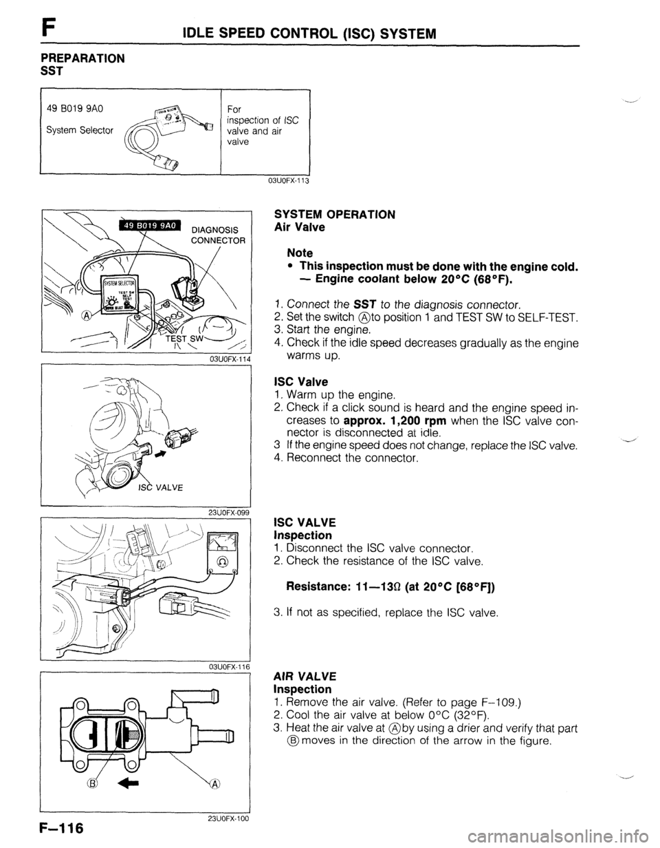
SYSTEM OPERATION
Air Valve
Note
l This inspection must be done with the engine cold.
- Engine coolant below 20°C (68°F).
1. Connect the SST to the diagnosis connector.
2. Set the switch @to position 1 and TEST SW to SELF-TEST.
3. Start the engine.
4. Check if the idle speed decreases gradually as the engine
warms up.
ISC Valve
1. Warm up the engine.
2. Check if a click sound is heard and the engine speed in-
creases to approx. 1,200 rpm when the ISC valve con-
nector is disconnected at idle.
3 If the engine speed does not change, replace the ISC valve.
4. Reconnect the connector.
ISC VALVE
Inspection
1. Disconnect the ISC valve connector.
2. Check the resistance of the ISC valve.
Resistance: 11-130 (at 20°C [68*F])
3. If not as specified, replace the ISC valve.
AIR VALVE
Inspection
1. Remove the air valve. (Refer to page F-109.)
2. Cool the air valve at below O°C (32OF).
3. Heat the air valve at @by using a drier and verify that part
@moves in the direction of the arrow in the figure.
Page 387 of 1164
FUEL PUMP CONNECTOR
/
REAR SEAT C
FUEL SYSTEM F
PRECAUTION
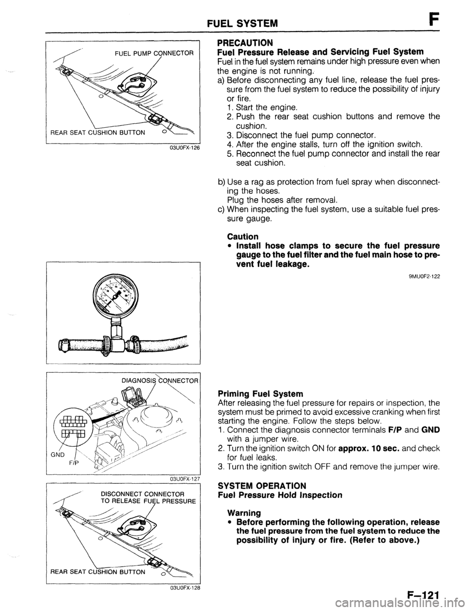
Fuel Pressure Release and Servicing Fuel System
Fuel in the fuel system remains under high pressure even when
the engine is not running.
a) Before disconnecting any fuel line, release the fuel pres-
sure from the fuel system to reduce the possibility of injury
or fire.
1. Start the engine.
2. Push the rear seat cushion buttons and remove the
cushion.
3. Disconnect the fuel pump connector.
4. After the engine stalls, turn off the ignition switch.
5. Reconnect the fuel pump connector and install the rear
seat cushion.
b) Use a rag as protection from fuel spray when disconnect-
ing the hoses.
Plug the hoses after removal.
c) When inspecting the fuel system, use a suitable fuel pres-
sure gauge.
Caution
l Install hose clamps to secure the fuel pressure
gauge to the fuel filter and the fuel main hose to pre-
vent fuel leakage.
9MUOF2-122 OBUOFX-126
DlAGNOS&O,NNECTOR
03UOFX-12.
-
DISCONNECT CONNECTOR
/ TO RELEASE FUEL PRESSURE
03UOFX-12;
Priming Fuel System
After releasing the fuel pressure for repairs or inspection, the
system must be primed to avoid excessive cranking when first
starting the engine. Follow the steps below.
1. Connect the diagnosis connector terminals
F/P and GND
with a jumper wire.
2. Turn the ignition switch
ON for approx. 10 sec. and check
for fuel leaks.
3. Turn the ignition switch OFF and remove the jumper wire.
SYSTEM OPERATION
Fuel Pressure Hold Inspection
Warning
l Before performing the following operation, release
the fuel pressure from the fuel system to reduce the
possibility of injury or fire. (Refer to above.)
F-121
Page 395 of 1164
FUEL SYSTEM F
STA
OBUOFX- 15
03UOFX-15
DISCONNECT CONNECTOR
TO RELEASE FUfL PRESSURE
REAR SEAT C
23UOFX-11
INSTALL CLAMPS
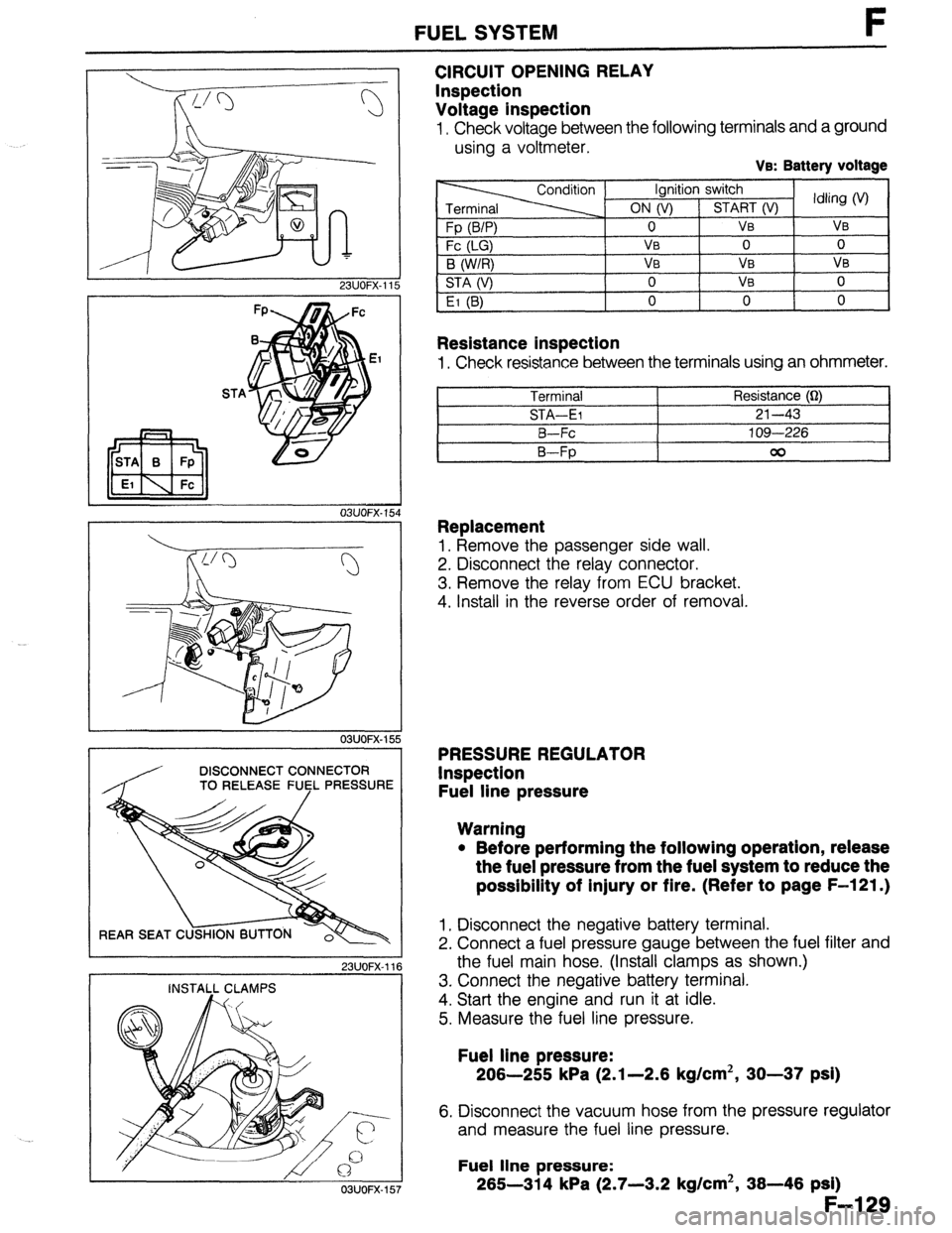
CIRCUIT OPENING RELAY
Inspection
Voltage inspection
I, Check voltage between the following terminals and a ground
using a voltmeter.
Ve: Battery voltage
Resistance inspection
1, Check resistance between the terminals using an ohmmeter.
Terminal Resistance (Q)
STA-El 21-43
B-Fc 109-226
B-Fp 00
Replacement
1, Remove the passenger side wall.
2. Disconnect the relay connector.
3. Remove the relay from ECU bracket.
4. Install in the reverse order of removal.
PRESSURE REGULATOR
Inspection
Fuel line pressure
Warning
l Before performing the following operation, release
the fuel pressure from the fuel system to reduce the
possibility of injury or fire. (Refer to page F-121.)
1, Disconnect the negative battery terminal.
2. Connect a fuel pressure gauge between the fuel filter and
the fuel main hose. (Install clamps as shown.)
3. Connect the negative battery terminal.
4. Start the engine and run it at idle.
5. Measure the fuel line pressure.
Fuel line pressure:
206-255 kPa (2.1-2.6 kg/cm2, 30-37 psi)
6. Disconnect the vacuum hose from the pressure regulator
and measure the fuel line pressure.
Fuel line pressure:
265-314 kPa (2.7-3.2 kg/cm2, 36-46 psi)
F-l 29
03UOFX-157