MAZDA PROTEGE 1992 User Guide
Manufacturer: MAZDA, Model Year: 1992, Model line: PROTEGE, Model: MAZDA PROTEGE 1992Pages: 1164, PDF Size: 81.9 MB
Page 11 of 1164
TOWING
.-
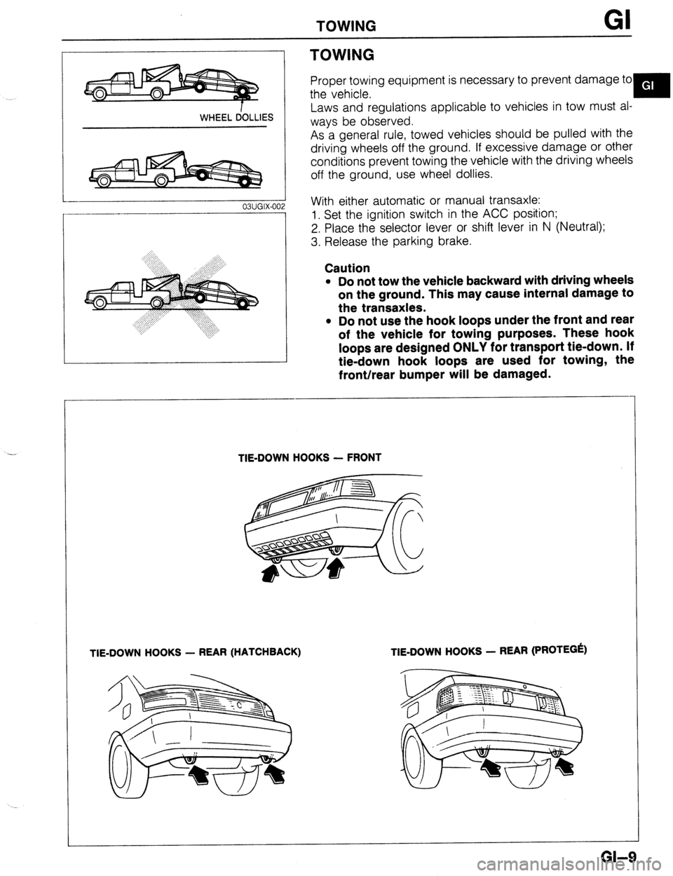
WHEEL dOLLlES
03UGIX-00
TOWING
Proper towing equipment is necessary to prevent damage to
the vehicle.
Y
Laws and regulations applicable to vehicles in tow must al-
ways be observed.
As a general rule, towed vehicles should be pulled with the
driving wheels off the ground. If excessive damage or other
conditions prevent towing the vehicle with the driving wheels
off the ground, use wheel dollies.
With either automatic or manual transaxle:
1. Set the ignition switch in the ACC position;
2. Place the selector lever or shift lever in N (Neutral);
3. Release the parking brake.
Caution
l Do not tow the vehicle backward with driving wheels
on the ground. This may cause internal damage to
the transaxles.
l Do not use the hook loops under the front and rear
of the vehicle for towing purposes. These hook
loops are designed ONLY for transport tie-down. If
tie-down hook loops are used for towing, the
front/rear bumper will be damaged.
TIE-DOWN HOOKS - FRONT
TIE-DOWN HOOKS - REAR (HATCHBACK) TIE-DOWN HOOKS - REAR (PROTEGk)
GI-9
Page 12 of 1164
GI IDENTIFICATION NUMBER LOCATIONS/UNITS/ABBREVlATlONS
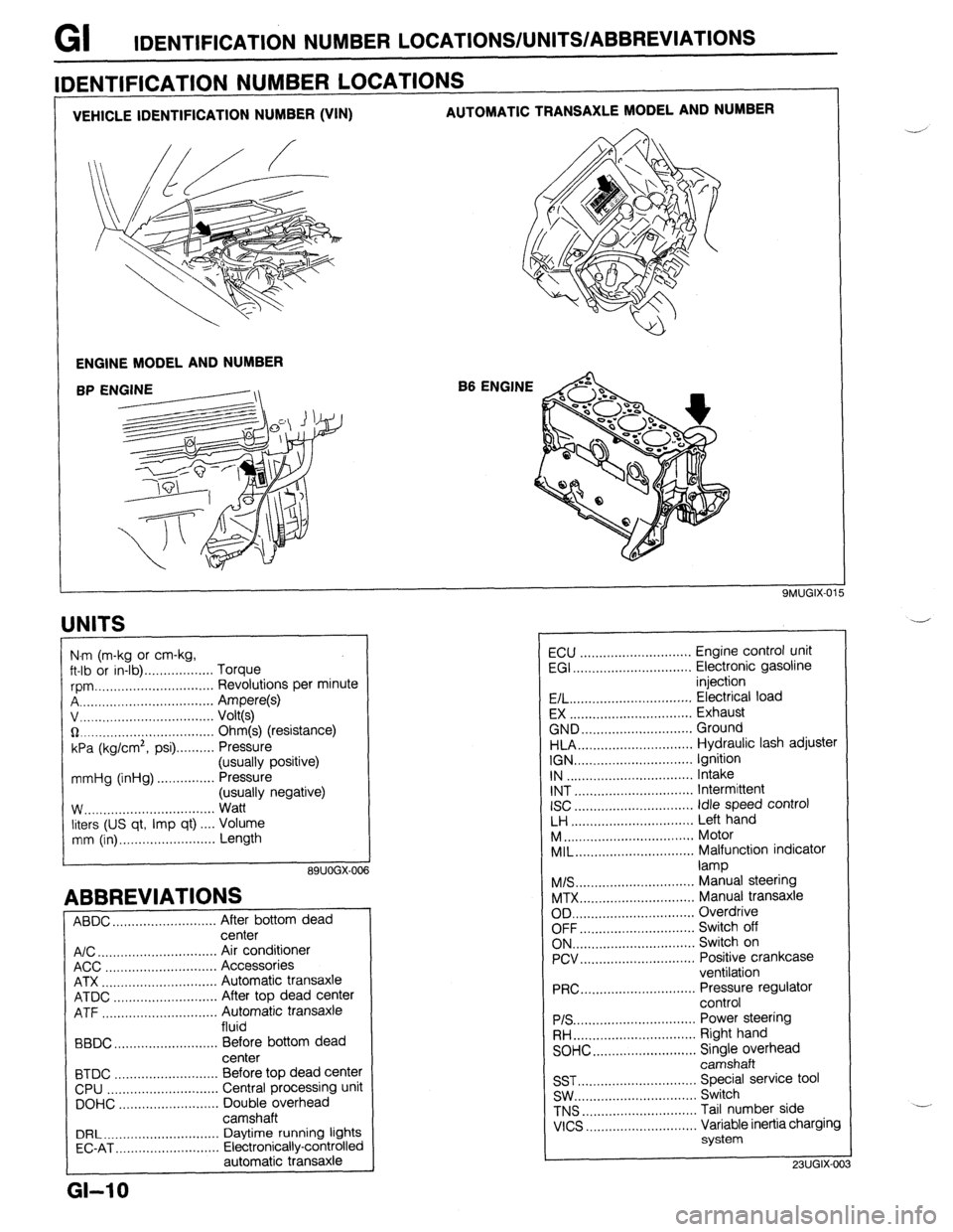
VEHICLE IDENTIFICATION NUMBER (VIN) AUTOMATIC TRANSAXLE MODEL AND NUMBER
ENGINE MODEL AND NUMBER
B6 ENGINE
IDENTIFICATION NUMBER LOCATIONS
UNITS
I
N.m (m-kg or cm-kg,
ft-lb or in-lb) . . . . . . . . . . . . . . . . . . Torque
rpm ._..,,,.............,.......... Revolutions per minute
A . . . . . . . . . . . . . . . . . Ampere(s)
v, . . . . . . . . . . . . . .
Volt(s)
$2 _....._..,......................... Ohm(s) (resistance)
kPa (kg/cm2,
psi) . . . . . . . . . . Pressure
(usually positive)
mmHg (inHg) . . . . . . . . . . . . . . . Pressure
(usually negative)
W.. . . . . . . . . . . .
Watt
liters (US qt, Imp qt) ,... Volume
mm (in) ..,......,...,........... Length
89UOGX-00
ABBREVIATIONS
ABDC . . . . . . . . . . . . . . . . . . . . .
After bottom dead
center
A/C . . . . . . . . . . . . . . . . . . . . . . . . . . . . . . .
Air conditioner
ACC ..,.,...... 3 . . . . . . . . . . . . . . . . . Accessories
ATX . . . . . . . . . . . . . . . . . . . . . . . . . . . . . . Automatic transaxle
ATDC ..,,...,...,............... After top dead center
ATF . . . . . . . . . . . . . . . . . Automatic transaxle
fluid
BBDC ,,..,.......,...,......,... Before bottom dead
center
BTDC .,......,...............,.. Before top dead center
CPU ..,,.......,...,..........,.. Central processing unit
DOHC ..,...,..,............,,.. Double overhead
camshaft
DRL ____.......................... Daytime running lights
EC-AT .,_.......,............,,.. Electronically-controlled
automatic transaxle
L
GI-10
ECU ............................. Engine control unit
EGI ............................... Electronic gasoline
injection
E/L.. .............................. Electrical load
EX ................................ Exhaust
GND.. ........................... Ground
HLA.. ............................ Hydraulic lash adjuster
IGN ............................... Ignition
IN ................................. Intake
INT ............................... Intermittent
ISC
............................... idle speed control
LH ................................ Left hand
M..
................................ Motor
MIL..
............................. Malfunction indicator
lamp
M/S..
............................. Manual steering
MTX.. ............................ Manual transaxle
OD ................................ Overdrive
OFF.. ............................ Switch off
ON.. .............................. Switch on
PCV.. ............................ Positive crankcase
ventilation
PRC..
............................ Pressure regulator
control
PIS ................................ Power steering
RH..
.............................. Right hand
SOHC.. .........................
z;;kiprhead
SST ............................... Special service tool
SW.. .............................. Switch
TNS
.............................. Tail number side
VICS
............................. Variable inertia charging
system
23UGIX-00
Page 13 of 1164
CAUTION GI
CAUTION
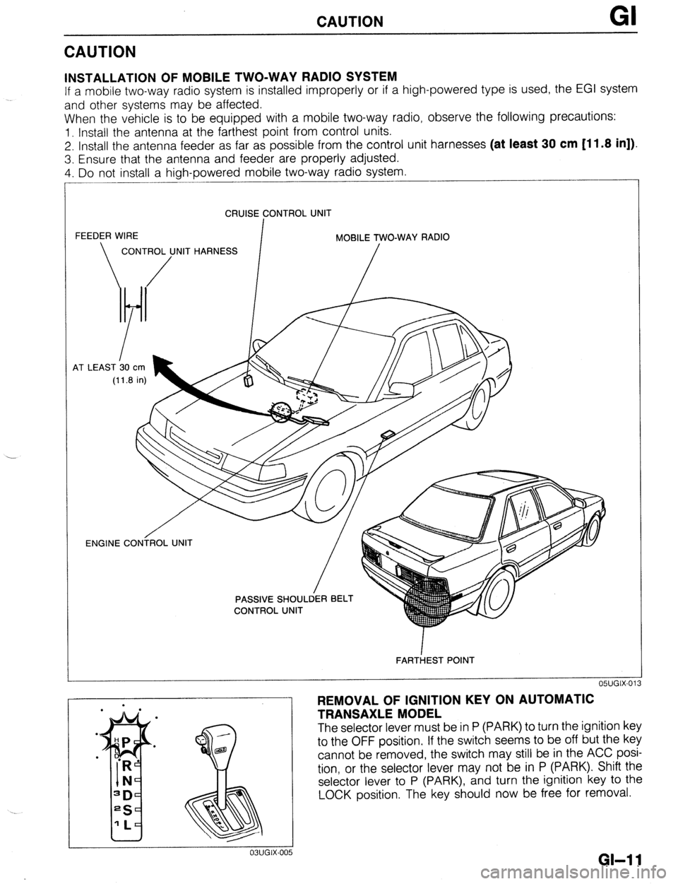
INSTALLATION OF MOBILE TWO-WAY RADIO SYSTEM
If a mobile two-way radio system is installed improperly or if a high-powered type is used, the EGI system
and other systems may be affected.
When the vehicle is to be equipped with a mobile two-way radio, observe the following precautions:
1. Install the antenna at the farthest point from control units.
2. Install the antenna feeder as far as possible from the control unit harnesses (at least 30 cm [11.8 in]).
3. Ensure that the antenna and feeder are properly adjusted.
4. Do not install a high-powered mobile two-way radio system.
CRUISE CONTROL UNIT
FEEDER WIRE
I MOBILE TWO-WAY RADIO
CONTROL UNIT HARNESS
/ /
4T LEAST b0
cm
(11.8 in)
OWGIX-013 ENGINE CONiROL UNIT
/
FARTiEST POINT
REMOVAL OF IGNITION KEY ON AUTOMATIC
TRANSAXLE MODEL
The selector lever must be in P (PARK) to turn the ignition key
to the OFF position. If the switch seems to be off but the key
cannot be removed, the switch may still be in the ACC posi-
tion, or the selector lever may not be in P (PARK). Shift the
selector lever to P (PARK), and turn the ignition key to the
LOCK position. The key should now be free for removal.
GI-1 1
Page 14 of 1164
GI CAUTION
1.4W or 3.4W
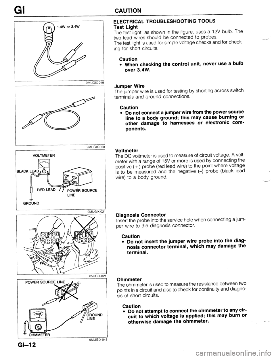
9MUGIX-019 ELECTRICAL TROUBLESHOOTING TOOLS
Test Light
The test light, as shown in the figure, uses a 12V bulb. The
two lead wires should be connected to probes.
The test light is used for simple voltage checks and for check-
ing for short circuits.
Caution
l When checking the control unit, never use a bulb
over 3.4W.
SMUGIX-621
VOLTMETER
BLACK
/ GR&ND
9MUGIX-021
05UGIX-021
YMUGIX-04
Jumper Wire
The jumper wire is used for testing by shorting across switch
terminals and ground connections.
Caution
l Do not connect a jumper wire from the power source
line to a body ground; this may cause burning or
other damage to harnesses or electronic com-
ponents.
Voltmeter
The DC voltmeter is used to measure of circuit voltage. A volt-
meter with a range of 15V or more is used by connecting the
positive (-t-) probe (red lead wire) to the point where voltage
is to be measured and the negative (-) probe (black lead
wire) to a body ground.
-,’
Diagnosis Connector
Insert the probe into the service hole when connecting a jum-
per wire to the diagnosis connector.
Caution
. Do not insert the jumper wire probe into the diag-
nosis connector terminal, which may damage the
terminal.
Ohmmeter
The ohmmeter is used to measure the resistance between two
points in a circuit and also to check for continuity and diagno-
sis of short circuits.
Caution
l Do not attempt to connect the ohmmeter to any cir-
cuit to which voltage is applied; this may burn or
otherwise damage the ohmmeter.
GI-12
Page 15 of 1164
. .-
CAUTION Gl
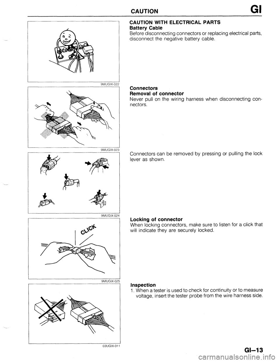
CAUTION WITH ELECTRICAL PARTS
Battery Cable
Before disconnecting connectors or replacing electrical parts,
disconnect the negative battery cable.
SMUGIX-022
YMUGIX-023
SMUGIX-02
SMUGIX-02
03UGIX-011 Connectors
Removal of connector
Never pull on the wiring harness when disconnecting con-
nectors.
Connectors can be removed by pressing or pulling the lock
lever as shown.
Locking of connector
When locking connectors, make sure to listen for a click that
will indicate they are securely locked.
Inspection
1. When a tester is used to check for continuity or to measure
voltage, insert the tester probe from the wire harness side.
GM 3
Page 16 of 1164
GI CAUTION
/
_____--__.. -I
OWGIX-028
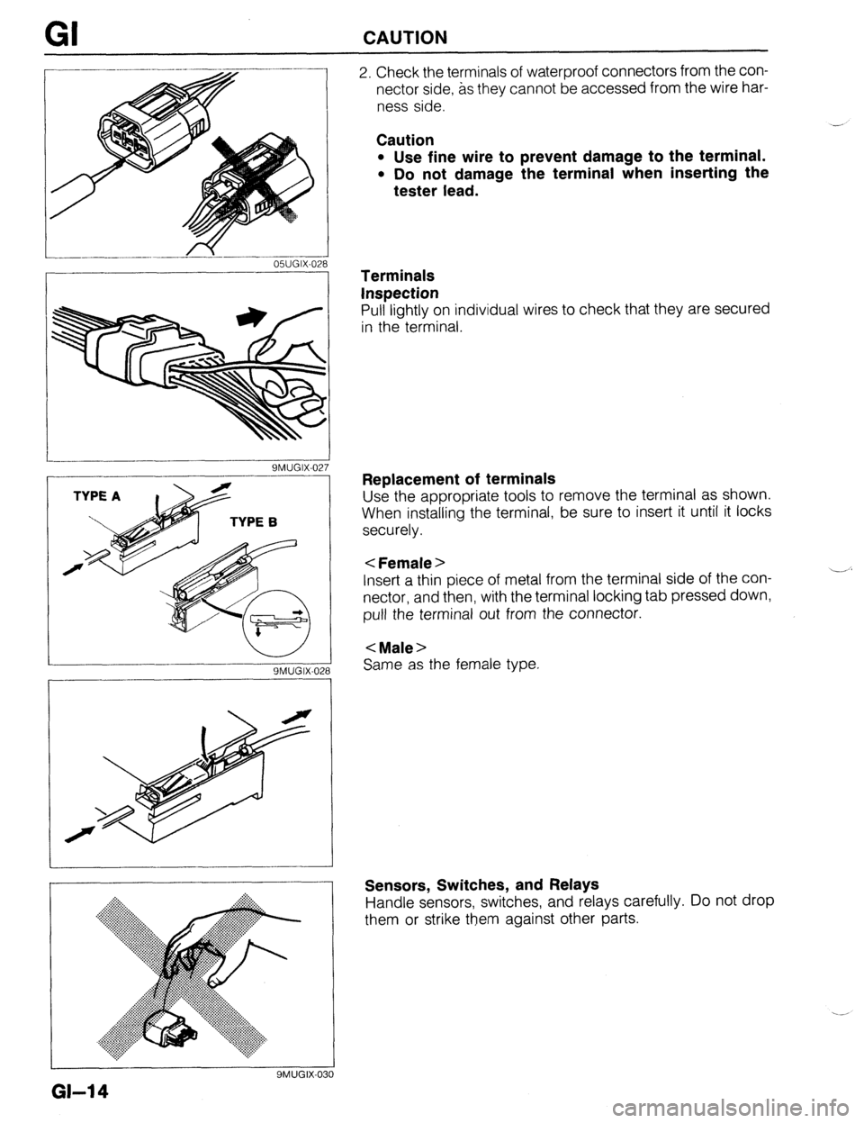
2. Check the terminals of waterproof connectors from the con-
nector side, as they cannot be accessed from the wire har-
ness side.
Caution
l Use fine wire to prevent damage to the terminal.
l Do not damage the terminal when inserting the
tester lead.
.- - 9MUGIX-027
9MUGIX-028
Same as the female type.
I
9MUGK031
Terminals
Inspection
Pull lightly on individual wires to check that they are secured
in the terminal.
Replacement of terminals
Use the appropriate tools to remove the terminal as shown.
When installing the terminal, be sure to insert it until it locks
securely.
< Female >
Insert a thin piece of metal from the terminal side of the con-
nectar, and then, with the terminal locking tab pressed down,
pull the terminal out from the connector.
< Male >
Sensors, Switches, and Relays
Handle sensors, switches, and relays carefully. Do not drop
them or strike them against other parts.
GI-14
Page 17 of 1164
CAUTION GI
9MUGIX-032
9MUGIX-029
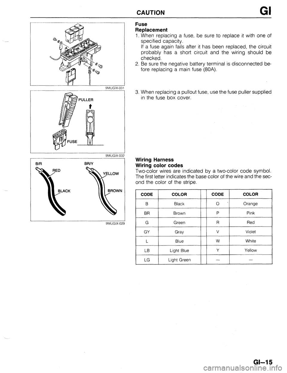
Fuse
Replacement
1. When replacing a fuse, be sure to replace it with one of
specified capacity.
If a fuse again fails after it has been replaced, the circuit
probably has a short circuit and the wiring should be
checked.
2. Be sure the negative battery terminal is disconnected be-
fore replacing a main fuse (80A).
3. When replacing a pullout fuse, use the fuse puller supplied
in the fuse box cover.
Wiring Harness
Wiring color codes
Two-color wires are indicated by a two-color code symbol.
The first letter indicates the base color of the wire and the sec-
ond the color of the stripe.
CODE COLOR
B Black
BR Brown
G Green
GY Gray
L Blue
LB Light Blue
LG Light Green CODE COLOR
0 Orange
P Pink
R Red
v Violet
w White
Y Yellow
- -
GI-15
Page 18 of 1164

Page 19 of 1164
A
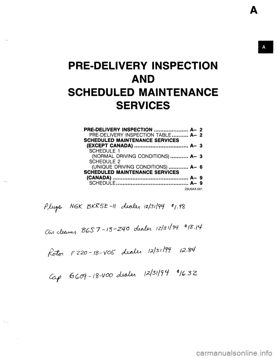
PRE-DELIVERY INSPECTION
AND
SCHEDULED MAINTENANCE
SERVICES
PRE-DELIVERY
INSPECTION
. . . . . . . . . . . . . . . . . . . . . A- 2
PRE-DELIVERY INSPECTION TABLE . . . . . . . . . . A-
2
SCHEDULED MAINTENANCE SERVICES
(EXCEPT CANADA)
. . . . . . . . . . . . ..I..................
A- 3
SCHEDULE 1
(NORMAL DRIVING CONDITIONS) . . . . . . . . . ,. A-
3
SCHEDULE 2
(UNIQUE DRIVING CONDITIONS) . . . . . . . . . . . . A-
6
SCHEDULED MAINTENANCE SERVICES
(CANADA)
. . . . . . . . . . . . . . . . . . . . . . . . . . . . . . . . . . . . . . ...‘....
A- 9
SCHEDULE
. . . . . . . . . . . . . . . . . . . . . . . . . . . . . . . . . . . . . . ...*..
A- 9
23UOAX-001
Page 20 of 1164
PRE-DELIVERY INSPECTION
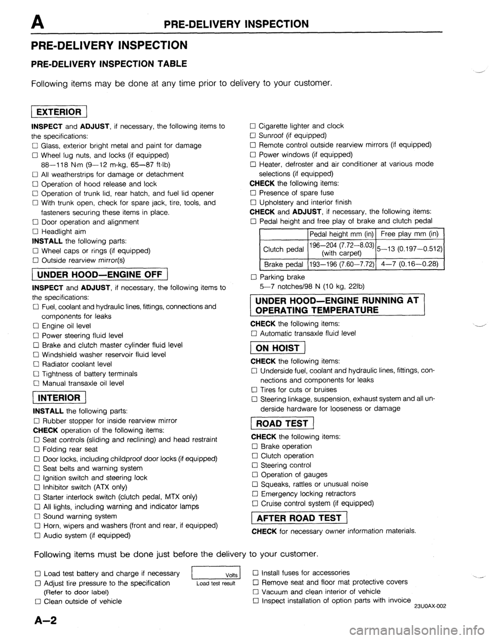
PRE-DELIVERY INSPECTION
PRE-DELIVERY INSPECTION TABLE
Following items may be done at any time prior to delivery to your customer.
INSPECT and ADJUST, if necessary, the following items to
the specifications:
0 Glass, exterior bright metal and paint for damage
Cl Wheel lug nuts, and locks (if equipped)
88-118 N.m (9-12 m-kg, 65-87 ft-lb)
q All weatherstrips for damage or detachment
0 Operation of hood release and lock
0 Operation of trunk lid, rear hatch, and fuel lid opener
Cl With trunk open, check for spare jack, tire, tools, and
fasteners securing these items in place.
Cl Door operation and alignment
Cl Headlight aim
INSTALL the following parts:
Cl Wheel caps or rings (if equipped)
q Outside rearview mirror(s)
1 UNDER HOOD-ENGINE OFF )
INSPECT and ADJUST, if necessary, the following items to
the specifications:
0 Fuel, coolant and hydraulic lines, fittings, connections and
components for leaks
Cl Engine oil level
0 Power steering fluid level
0 Brake and clutch master cylinder fluid level
El Windshield washer reservoir fluid level
Cl Radiator coolant level
Cl Tightness of battery terminals
Cl Manual transaxle oil level
riizmiq
INSTALL the following parts:
Cl Rubber stopper for inside rearview mirror
CHECK operation of the following items:
0 Seat controls (sliding and reclining) and head restraint
Cl Folding rear seat
0 Door locks, including childproof door locks (if equipped)
Seat belts and warning system
Cl Ignition switch and steering lock
0 Inhibitor switch (ATX only)
U Starter interlock switch (clutch pedal, MTX only)
Cl All lights, including warning and indicator lamps
Cl Sound warning system
Cl Horn, wipers and washers (front and rear, if equipped)
0 Audio system (if equipped) 0 Cigarette lighter and clock
0 Sunroof (if equipped)
II Remote control outside rearview mirrors (if equipped)
Cl Power windows (if equipped)
q Heater, defroster and air conditioner at various mode
selections (if equipped)
CHECK the following items:
Cl Presence of spare fuse
0 Upholstery and interior finish
CHECK and ADJUST, if necessary, the following items:
0 Pedal height and free play of brake and clutch pedal
Pedal height mm (in) Free play mm (in)
0 Parking brake
5-7 notches/98 N (10 kg, 22lb)
UNDER HOOD-ENGINE RUNNING AT
OPERATING TEMPERATURE
CHECK the following items:
q Automatic transaxle fluid level
[I
CHECK the following items:
Cl Underside fuel, coolant and hydraulic lines, fittings, con-
nections and components for leaks
0 Tires for cuts or bruises
0 Steering linkage, suspension, exhaust system and all un-
derside hardware for looseness or damage
[I
CHECK the following items:
0 Brake operation
0 Clutch operation
Cl Steering control
Cl Operation of gauges
q Squeaks, rattles or unusual noise
Cl Emergency locking retractors
0 Cruise control system (if equipped)
1 AFTER ROAD TEST (
CHECK for necessary owner information materials.
Following items must be done just before the delivery to your customer.
q Load test battery and charge if necessary
1 Volts 1 0 Install fuses for accessories
i.. _
0 Adjust tire pressure to the specification
Load test result cl Remove seat and floor mat protective covers
(Refer to door label) 0 Vacuum and clean interior of vehicle
0 Clean outside of vehicle q Inspect installation of option parts with invoice
23UOAX-002
A-2