MAZDA PROTEGE 1992 Repair Manual
Manufacturer: MAZDA, Model Year: 1992, Model line: PROTEGE, Model: MAZDA PROTEGE 1992Pages: 1164, PDF Size: 81.9 MB
Page 51 of 1164

ON-VEHICLE MAINTENANCE Bl
Removal note
Rocker arm and rocker shaft assembly
1. Loosen the rocker arm bolts in two or three steps in the or-
der shown in the figure.
2. Remove the rocker arms and rocker shaft assembly.
3. Code all rocker arms and springs so that they can be rein-
stalled in the same places from which they were removed.
I
23UOBi-02 1
Installation note
HLA
1. Pour engine oil into the oil reservoir in the rocker arm.
2. Apply engine oil to the new HLA.
3. Install the HLA in the rocker arm.
Caution
l Be careful not to damage the O-ring when installing.
Oli RESERVOIR
o3uoB1-o?
Rocker arm and rocker shaft assembly
B6 SOHC
1. Assemble the rocker arm and rocker shaft assembly as
shown in the figure. No.1 CYLINDER No.4 CYLINDEF
[ ’ ” 0 D 0
0311081-034
Caution
l Be sure both rocker arm shaft oil holes face
downward.
l The installation bolt holes are different for the ex-
haust and intake sides as shown in the figure. No.1 CYLINDER
No.4 CYLINDER
INTAKE
l---A--l
0 = ‘, I I
Y Y
0 \L
.a Y
r Y)
/
6
EXHAUST
A>B
Note
l There are two types of rocker arms with different
offsets. One type for No.1 and No.2 cylinders ex-
haust and intake. And the other for cylinders No.3
and No.4.
No. 1.2 CYLINDERS No.3,4 CYLINDERS
(IN & EX) (IN & EX)
81-21
Page 52 of 1164

Bl ON-VEHICLE MAINTENANCE
8 e
93UOlA.08
EX
03UOBl-035
HEAD COVER
)
23UOBl-023
Steps After Installation
1, Connect the negative battery cable.
2. Start the engine and fully warm up.
3. Verify that there is no tappet noise. 2. Install the rocker arm and rocker shaft assembly.
Caution
l The bolts must be tightened gradually and in the or-
der shown in the figure.
Tightening torque:
22-28 N-m (2.2-2.9 m-kg, 18-21 ft-lb)
BP SOHC
1. Assemble the rocker arm and rocker shaft assembly as
shown in the figure.
Caution
l Face the rocker shaft identification mark upward.
l The installation bolt holes are different for the ex-
haust and intake sides.
Identification mark
IN . . . . . . . . . . White
EX . . . . . . . . . . . Blue
2. Install the rocker arm and rocker shaft assembly.
3. Tighten the rocker arm bolts in two or three steps in the or-
der shown in the figure.
Tightening torque:
22-28 Nsrn (2.2-2.9 m-kg, 16-21 ft-lb)
Cylinder head cover
1. Install the cylinder head cover.
Tightening torque
Bolt @:
4.9-8.8 N-m (50-90 cmikg, 43-78 in-lb)
Bolt @:
7.8-l 1 Nnrn (80-l 10 cm-kg, 69-95 in-lb)
Caution
l If the head cover gasket is reused, apply sealant in
the groove as shown.
03UOBl-038
.-
Bl-22
Page 53 of 1164

ON-VEHICLE MAINTENANCE
FRONT OIL SEAL
Replacement
1. Disconnect the negative battery cable.
2. Remove in the order shown in the figure, referring to
Removal Note.
3. Install in the reverse order of removal, referring to Installation Note.
I- I
I
I
I
157-167 (16-17, 116-123)
I
t
I
I
/
L---- -____ - _......_____________ -----------!
N.m (m-kg, It-lb)
^ ^ ^ -
_ _
1. Timing belt
- 3. Timing belt pulley
Removal I Installation..
.............. page
61-12 Installation
Note.. ......................
page Bl-24
2. Pulley lock bolt
4. Oil seal
Installation Note ........................
page Bl-24
Removal Note
..................................... below
Installation
Note.. ......................
page Bl-24
01 EOBX-055
Removal Note
Oil seal
1. Cut the oil seal lip with a razor knife.
2. Remove the oil seal with a screwdriver protected with a rag.
61-23
Page 54 of 1164

Bl ON-VEHICLE MAINTENANCE
01 EOBX-056
23UOBi -0:
Steps After Installation
1. Lower the vehicle.
2. Connect the negative battery cable.
3. Start the engine and check the ignition timing.
(Refer to page 61-8)
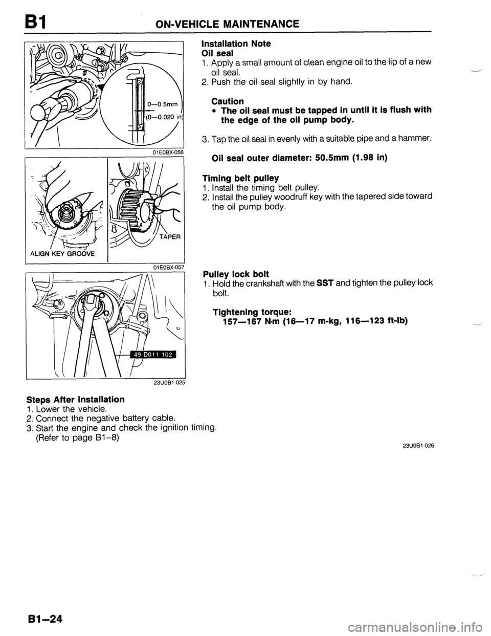
Installation Note
Oil seal
1. Apply a small amount of clean engine oil to the lip of a new
oil seal.
2. Push the oil seal slightly in by hand.
Caution
l The oil seal must be tapped in until it is flush with
the edge of the oil pump body.
3. Tap the oil seal in evenly with a suitable pipe and a hammer.
Oil seal outer diameter: 50.5mm (1.98 in)
Timing belt pulley
1. Install the timing belt pulley.
2. Install the pulley woodruff key with the tapered side toward
the oil pump body.
Pulley lock bolt
1. Hold the crankshaft with the SST and tighten the pulley lock
bolt.
Tightening torque:
157-167 N*rn (16-17 m-kg, 116-123 ft-lb)
23UOBi-026
Bl-24
Page 55 of 1164

-.
ON-VEHICLE MAINTENANCE Bl
REAR OIL SEAL
Replacement
1. Disconnect the negative battery cable.
2. Remove in the order shown in the figure, referring to
Removal Note.
3. install in the reverse order of removal, referring to Installation Note !.
I
16-26 (1.6-2.7, 13-20) I HTX
ATX
N.m (m-kg, R-lb)
23UOBl-027
1. Transaxle
MTX
Service.. ............................... Sections Jl , J2
ATX
Service .......................................... Section K
2. Clutch cover, clutch disc
Service .......................................... Section H 3. Flywheel (MTX)
Removal Note ..................................... below
Installation Note ........................ page 81-26
4. Drive plate (ATX)
Removal Note.. ......................... page Bl-26
Installation Note.. ...................... page Bl-27
5. Oil seal
Removal Note.. ......................... page 81-26
Installation Note ........................ page 81-26
Removal note
Flywheel (MTX)
1. Hold the flywheel with the SST or equivalent.
2. Remove the flywheel lock bolts.
3. Remove the flywheel.
Bl-25
Page 56 of 1164

Bl ON-VEHICLE MAINTENANCE
OIL SEAL LIP
L I I
OWOBX-063
05UOBX-069
Drive plate (ATX)
1. Hold the drive plate with the SST or equivalent.
2. Remove the drive plate lock bolts.
3. Remove the backing plate, drive plate, and adapter.
Oil seal
1. Cut the oil seal lip with a razor knife.
2. Remove the oil seal with a screwdriver protected with a rag.
Installation note
Oil seal
1. Apply a small amount of clean engine oil to the lip of a new
oil seal.
2. Push the oil seal slightly in by hand.
Caution
l The oil seal must be tapped in until it is flush with
the edge of the rear cover.
3. Tap the oil seal in evenly with a suitable pipe and a hammer.
Oil seal outer diameter: 1OOmm (3.94 in)
Flywheel (MTX)
1. Remove the sealant from the flywheel bolt holes in the crank-
shaft and from the flywheel bolts.
Caution
l If all the previous sealant cannot be removed from
a bolt, replace the bolt.
l Do not apply sealant if a new bolt is used.
2. Set the flywheel onto the crankshaft.
3. Apply sealant to the flywheel bolts and install them.
4. Hold the flywheel with the SST or equivalent.
5. Tighten the bolts in two or three steps in the order shown
in the figure.
Tightening torque:
96-103 N-m (9.6-10.5 m-kg, 71-76 ft-lb)
Page 57 of 1164

Bl
03UOBl-01 15
23UOBl-066
Drive plate (ATX)
1. Remove the sealant from the drive plate bolt holes in the
crankshaft and from the drive plate bolts.
Caution
l If all the previous sealant cannot be removed from
a bolt, replace the bolt.
l Do not apply new sealant if a new bolt is used.
2. Install the adapter, drive plate, and backing plate onto the
crankshaft.
3. Apply sealant to the drive plate bolts and install them.
4. Hold the drive plate with the
SST or equivalent.
5. Tighten the bolts in two or three steps in the order shown
in the figure.
Tightening torque:
96-103 N-m (9.8-10.5 m-kg, 71-76 ft-lb)
Steps After Installation
1. Connect the negative battery cable.
2. Start the engine and perform engine adjustments as necessary.
-.
05UOBX-072
81-27
Page 58 of 1164

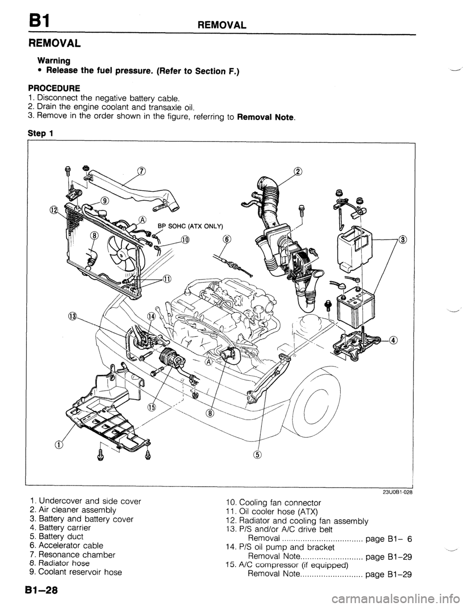
REMOVAL
REMOVAL
Warning
l Release the fuel pressure. (Refer to Section F.)
PROCEDURE
1. Disconnect the negative battery cable.
2. Drain the engine coolant and transaxle oil.
3. Remove in the order shown in the figure, referring to Removal Note,
Step 1
1. Undercover and side cover
2. Air cleaner assembly 10. Cooling fan connector
3. Battery and battery cover 11. Oil cooler hose (ATX)
4. Battery carrier 12. Radiator and cooling fan assembly
13. P/S and/or A/C drive belt
5. Battery duct
Removal . . . . . . . . . . . . . . . . . . . . . . . . . . . . . . . . . . .
6. Accelerator cable page Bl- 6
7. Resonance chamber 14. P/S oil pump and bracket
8. Radiator hose Removal Note . . . . . . . . . . . . . . . . . . . . . . . . . . . page 81-29
9. Coolant reservoir hose 15. A/C compressor (if equipped)
Removal Note . . . . . . . . . . . . . . . . . . . . . . . . . . . page 81-29
81-28
Page 59 of 1164

REMOVAL I31
Step 2
2311081-O: ii
1.
Disconnect the harness connectors shown in the figure.
Removal note
P/S oil pump
Caution
l Do not damage the hoses.
1. Remove the P/S oil pump with the hoses still connected.
2. Position the pump away from the engine and affix it with wire.
A/C compressor (if equipped)
Caution
l Do not damage the hoses.
1, Remove the A/C compressor with the hoses still connected.
2. Position the compressor away from the engine and affix it
with wire.
ALTERNATOR
OIL PRESSURE SWITCH
GROUND THROTTLE SENSOR
------- I
INJECTOR
NEUTRAL SWITCH (MTX)
Page 60 of 1164

Bl REMOVAL
Step 3
1. Disconnect the hoses shown in the figure.
BP SOHC
1. Brake vacuum hose
2. Fuel hose
Removal
Note . . . . . . . . . . . . . . . . . . . . . . . . . . . . . . . . . . .
Bl-30
05UOBX-078
03UOBi -050
below 3. Vacuum hose (Purge control)
4. Vacuum hose (Cruise control)
5. Heater hose
Removal Note ..,,,................................ below
Removal note
Fuel hose
Warning
l Keep sparks and open flame away from the fuel
area.
Caution
l Cover the hose with a rag because fuel will spray
out when disconnecting.
l Plug the disconnected hoses to avoid fuel leakage.
1. Disconnect the fuel hoses.
Heater hose
Caution
l Heater hose joint has O-rings and spacer.
l Do not lose them when removing.
1. Push the heater hose retainer and remove the heater hose.