MAZDA PROTEGE 1992 Service Manual
Manufacturer: MAZDA, Model Year: 1992, Model line: PROTEGE, Model: MAZDA PROTEGE 1992Pages: 1164, PDF Size: 81.9 MB
Page 41 of 1164
ON-VEHICLE MAINTENANCE Bl
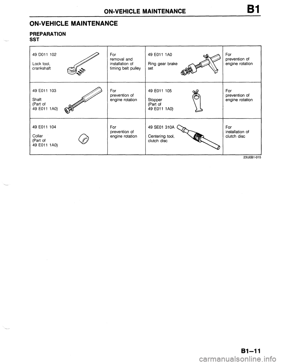
ON-VEHICLE MAINTENANCE
PREPARATION
SST
49 DO1 1 102
Lock tool,
crankshaft For
removal and
installation of
timing belt pulley 49 EOll 1AO
Ring gear brake
set For
prevention of
engine rotation
49 EOll 103
For
49 EOl 1 105
For
prevention of
prevention of
Shaft
engine rotation
Stopper
engine rotation
(Part of
(Part of
49 EOl 1 1AO)
49 EOI 1 1AO)
49 EOll 104
For
49 SE01 310A
For
prevention of
installation of
Collar
engine rotation
Centering tool,
clutch disc
(Part of
clutch disc
49 EOl 1 1 AO)
23UOBl-01
81-11
Page 42 of 1164
Bl ON-VEHICLE MAINTENANCE
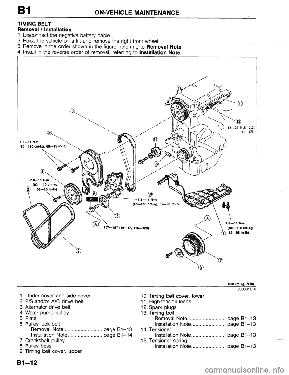
TIMING BELT
Removal / Installation
1. Disconnect the negative battery cable.
2. Raise the vehicle on a lift and remove the right front wheel.
3. Remove in the order shown in the figure, referring to
Removal Note.
4. Install in the reverse order of removal, referrina to Installation Note.
7.6-11 N.m
[SO-110 cm-kg, 69-95 in-lb)
7.6-11 N.m
(60-l 10 cm-kg,
0 69-95 in-lb)
, .v- I . (60-110 cm-kg, 69-95 in-lb)
157-167 (16-17, 116-123) /@ 7.i11 N.m
(60-110 cm-kg,
69-95 in-lb)
N.m (m-kg, ft-lb]
23UOBl-01
1. Under cover and side cover 10. Timing belt cover, lower
2. P/S and/or A/C drive belt 11. High-tension leads
3. Alternator drive belt 12. Spark plugs
4. Water pump pulley 13. Timing belt
5. Plate Removal Note . . . . . . . . . . . . . . . . . . . . . . . . . . . page Bl-13
6. Pulley lock bolt Installation Note . . . . . . . . . . . . . . . . . . . . . . . . page Bl-13
Removal Note ..,.,,.,....,....,...,...,, page Bl-13 14. Tensioner
installation Note . . . . . . . . . . . . . . . . . . . . . . . . page Bl-14 Installation Note . . . . . . . . . . . . . . . . . . . . . . . . page 81-13
7. Crankshaft pulley 15. Tensioner spring .__
8. Pulley boss Installation Note . . . . . . . . . . . . . . . . . . . . . . . . page 61-13
9. Timing belt cover, upper
131-12
Page 43 of 1164
-
. . .
ON-VEHICLE MAINTENANCE Bl
13EOBl-010
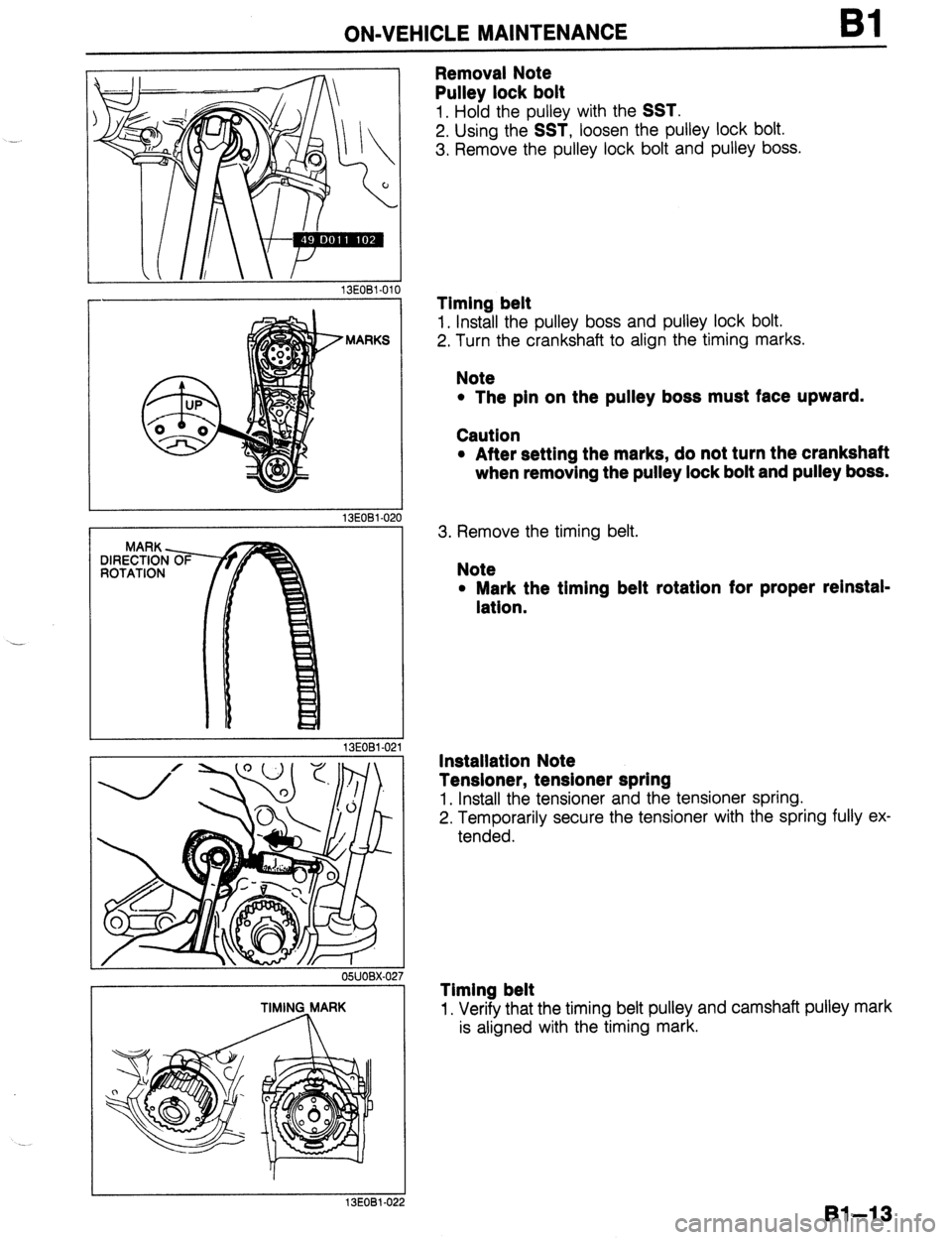
Removal Note
Pulley lock bolt
1. Hold the pulley with the SST.
2. Using the SST, loosen the pulley lock bolt.
3. Remove the pulley lock bolt and pulley boss.
MARKS
13EOBl-02
MARK -
DIRECTION
ROTATION
13EOBl-02
OBUOBX-0;
TIMING MARK
13EOBl.022
Timing belt
1. Install the pulley boss and pulley lock bolt.
2. Turn the crankshaft to align the timing marks.
Note
l The pin on the pulley boss must face upward.
Caution
l After setting the marks, do not turn the crankshaft
when removing the pulley lock bolt and pulley boss.
3. Remove the timing belt.
Note
l Mark the timing belt rotatlon for proper relnstal-
latlon.
Installation Note
Tensioner, tensioner spring
1. Install the tensioner and the tensioner spring.
2. Temporarily secure the tensioner with the spring fully ex-
tended.
Timing belt
1. Verify that the timing belt pulley and camshaft pulley mark
is aligned with the timing mark.
Bl-13
Page 44 of 1164
Bl ON-VEHICLE MAINTENANCE
13EOBl-023
MARKS
13EOBl-02, 4
I
03UOBl-02
98 N
(10 kg, 22 lb)
13EOBl-02 15
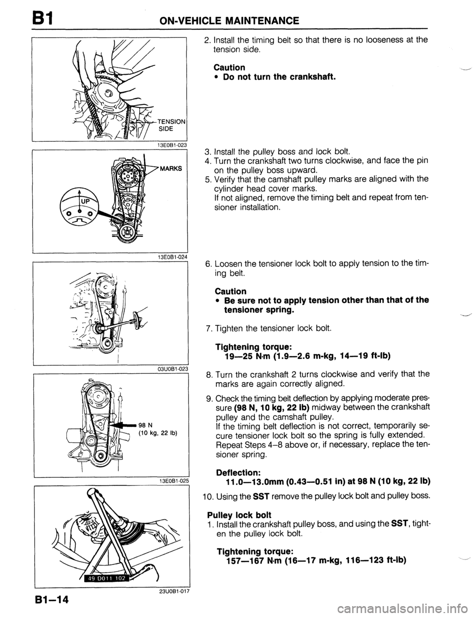
2. Install the timing belt so that there is no looseness at the
tension side.
Caution
l Do not turn the crankshaft. .-
3. Install the pulley boss and lock bolt.
4. Turn the crankshaft two turns clockwise, and face the pin
on the pulley boss upward.
5. Verify that the camshaft pulley marks are aligned with the
cylinder head cover marks.
If not aligned, remove the timing belt and repeat from ten-
sioner installation.
6. Loosen the tensioner lock bolt to apply tension to the tim-
ing belt.
Caution
l Be sure not to apply tension other than that of the
tensioner spring.
7. Tighten the tensioner lock bolt.
--
Tightening torque:
19-25 N,m (1.9-2.6 m-kg, 14-19 ft-lb)
8. Turn the crankshaft 2 turns clockwise and verify that the
marks are again correctly aligned.
9. Check the timing belt deflection by applying moderate pres-
sure (96 N,
10 kg, 22 lb) midway between the crankshaft
pulley and the camshaft pulley.
If the timing belt deflection is not correct, temporarily se-
cure tensioner lock bolt so the spring is fully extended.
Repeat Steps 4-8 above or, if necessary, replace the ten-
sioner spring.
Deflection:
11 .O-13.0mm (0.43-0.51 in) at 96 N (10 kg, 22 lb)
10. Using the SST remove the pulley lock bolt and pulley boss.
Pulley lock bolt
1. Install the crankshaft pulley boss, and using the SST, tight-
en the pulley lock bolt.
Tightening torque:
157-167 N,m (16-17 m-kg, 116-123 ft-lb)
91-14
Page 45 of 1164
ON-VEHICLE MAINTENANCE Bl
Steps After Installation
1. Connect the negative battery cable.
2. Start the engine and check as follows:
l Ignition timing. (Refer to page 91-8.)
03UOBl-026
. .
81-15
Page 46 of 1164
Bl ON-VEHICLE MAINTENANCE
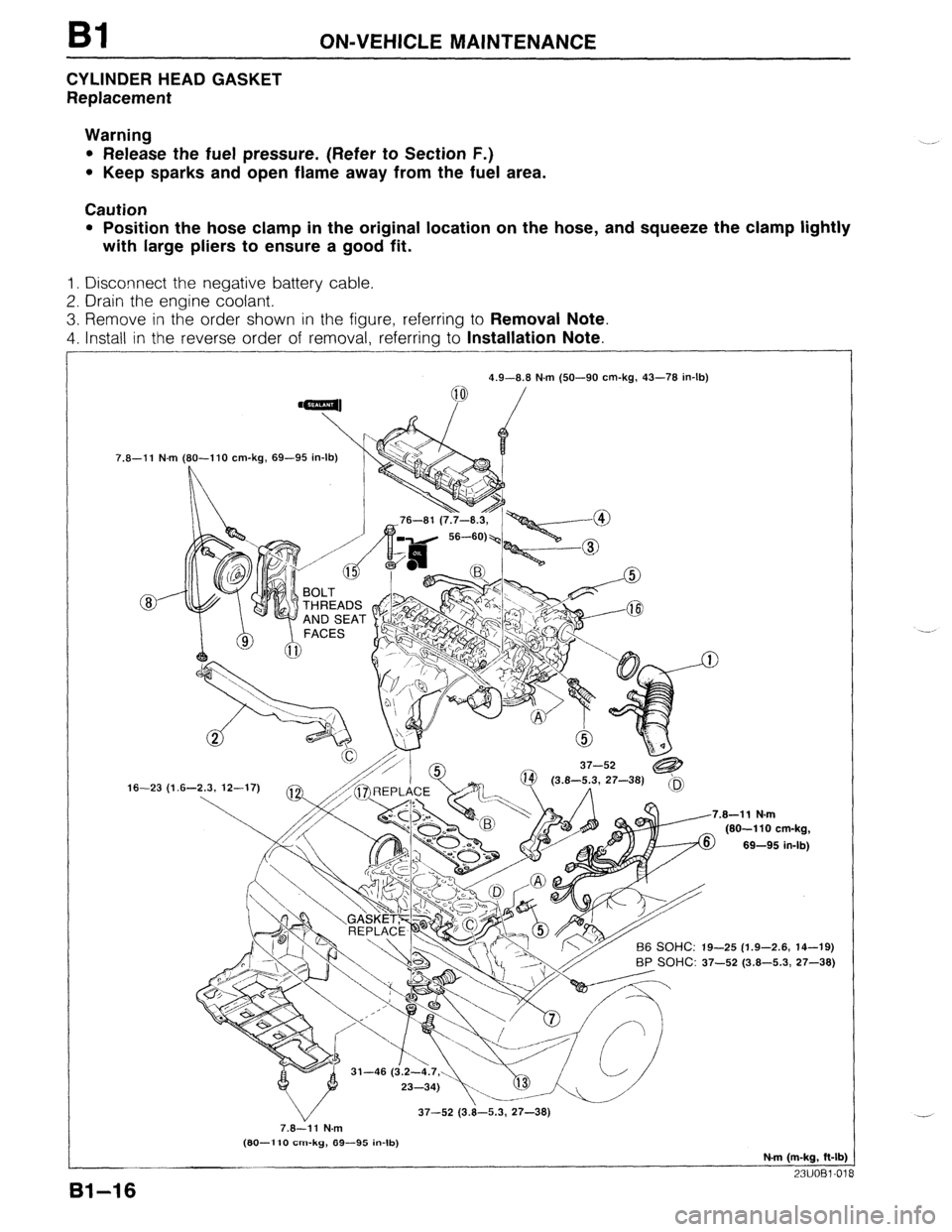
CYLINDER HEAD GASKET
Replacement
Warning
l Release the fuel pressure. (Refer to Section F.)
l Keep sparks and open flame away from the fuel area.
Caution
l Position the hose clamp in the original location on the hose, and squeeze the clamp lightly
with large pliers to ensure a good fit.
1. Disconnect the negative battery cable.
2. Drain the engine coolant.
3. Remove in the order shown in the figure, referring to Removal Note.
4. Install in the reverse order of removal, referring to Installation Note.
7.8-11 N.m
16-23 (1 4.9-8.8 N.m (50-90 cm-kg, 43-78 in-lb)
(80-l 10 cm-kg, 69-95 in-lb)
L
.8-11 N.m
(80-110 cm-kg,
69-95 in-lb)
-25 (1.9-2.6, 14-19)
BP SOHC: 37-52 (3.8-5.3, 27-38)
37-52 (3.8-5.3, 27-38)
7.8-11 N.m
(80-l 10 cm-kg, 89-95 in-lb)
N-m (m-kg, ft-lb)
23UOBl-01
81-16
Page 47 of 1164
ON-VEHICLE MAINTENANCE Bl
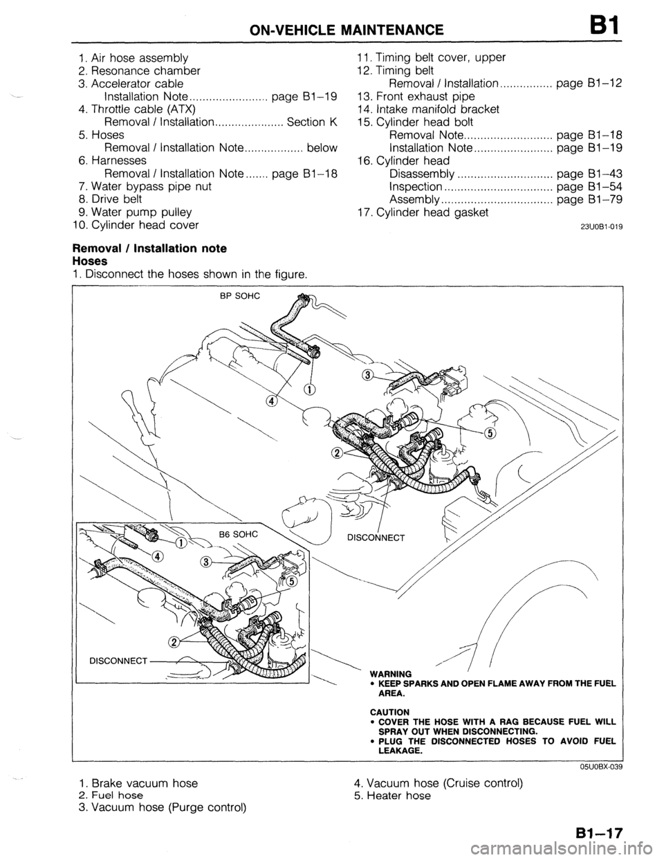
I. Air hose assembly 1 I. Timing belt cover, upper
2. Resonance chamber 12. Timing belt
3. Accelerator cable Removal / Installation.. . . . . . . . . . . . . . . page Bl-12
Installation Note . . . . . . . . . . . . . . . . . . . . . . . . page BI-I9 13. Front exhaust pipe
4. Throttle cable (ATX)
14. Intake manifold bracket
Removal / Installation . . . . . . . . . . . . . . . . . . . . . Section K 15. Cylinder head bolt
5. Hoses Removal Note . . . . . . . . . . . . . . . . . . . . . . . . . . . page BI-18
Removal I Installation Note ..,............... below Installation Note . . . . . . . . . . . . . . . . . . . . . . . . page Bl-I9
6. Harnesses 16. Cylinder head
Removal I Installation Note....... page BI-I8 Disassembly . . . . . . . . . . . . . . . . . . . . . . . . . . . . page 61-43
7. Water bypass pipe nut
Inspection . . , . . . . . . . . . . . . . . . . . . . . . . . . . ., . . page BI -54
8. Drive belt Assembly . . . . . . . . . . . . . . . . . . . . . . . . . . . . . . . . . . page BI-79
9. Water pump pulley 17. Cylinder head gasket
10. Cylinder head cover
23UOBl-019
Removal / Installation note
Hoses
I. Disconnect the hoses shown in the figure.
\ / DlSCOtjNECT
, w I.,,, -----. WARNING ’ ’ ’ l KEEP SPARKS AND OPEN FLAME AWAY FROM THE FUEL
AREA.
CAUTION
l COVER THE HOSE WITH A RAG BECAUSE FUEL WILL
SPRAY OUT WHEN DISCONNECTING.
. PLUG THE DISCONNECTED HOSES TO AVOID FUEL
LEAKAGE.
I. Brake vacuum hose
2. Fuel hose
3. Vacuum hose (Purge control) 4. Vacuum hose (Cruise control)
5. Heater hose
Page 48 of 1164
Bl ON-VEHICLE MAINTENANCE
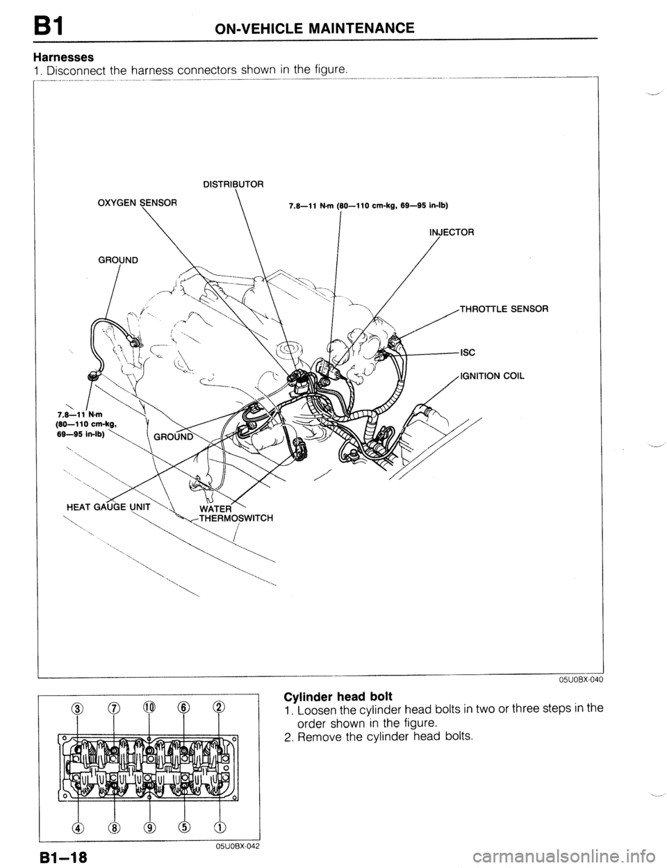
Harnesses
1. Disconnect the harness connectors shown in the figure.
DISTRIBUTOR
OXYGEN SENSOR
7.8-l 1 N.m (80-I 10 cm-kg, 69-95 in-lb)
I
INJECTOR
GROUND
/
7.8-11 N-m
(80-110 cm-kg,
HEAT GAijijE
Cylinder head bolt
1, Loosen the cylinder head bolts in two or three steps in the
order shown in the figure.
2. Remove the cylinder head bolts.
Page 49 of 1164
.
ON-VEHICLE MAINTENANCE
Installation note
Cylinder head bolt Bl
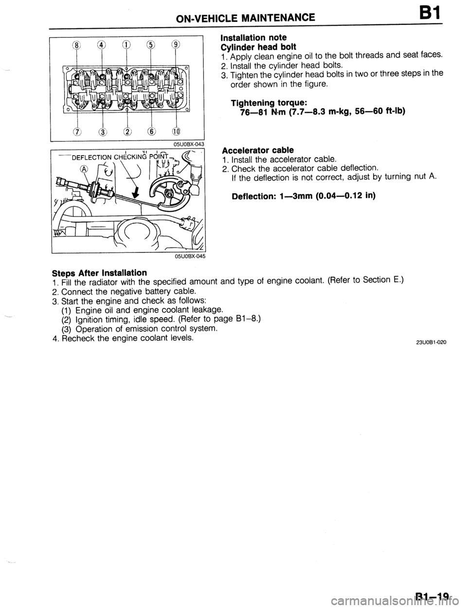
1. Apply clean engine oil to the bolt threads and seat faces.
2. Install the cylinder head bolts.
3. Tighten the cylinder head bolts in two or three steps in the
order shown in the figure.
Tightening torque:
76-61 N#m (7.7-6.3 m-kg, 56-60 f&lb)
Accelerator cable
1. Install the accelerator cable.
2. Check the accelerator cable deflection.
If the deflection is not correct, adjust by turning nut A.
Deflection: I-3mm (0.04-0.12 in)
Steps After Installation
1. Fill the radiator with the specified amount and type of engine coolant. (Refer to Section E.)
2. Connect the negative battery cable.
3. Start the engine and check as follows:
(1) Engine oil and engine coolant leakage.
(2) Ignition timing, idle speed. (Refer to page 81-8.)
(3) Operation of emission control system.
4. Recheck the engine coolant levels.
2311081-020
Bl-19
Page 50 of 1164
Bl ON-VEHICLE MAINTENANCE
HLA
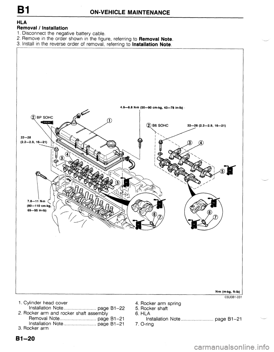
Removal / Installation
1. Disconnect the negative battery cable.
2. Remove in the order shown in the figure, referring to
Removal Note.
3. Install in the reverse order of removal, referring to Installation Note.
-
4.9-0.8 N.I
@ BP SOHC
22-28
12.2-2.9. 16-2 m (SO-SO cm-kg, 43-78 in-lb)
N.m (m-kg, ft-lb)
03UOBl-03
1. Cylinder head cover
Installation
Note . . . . . . . . . . . . . . . . . . . . . . . . page 4. Rocker arm spring
81-22
5. Rocker shaft
2. Rocker arm and rocker shaft assembly
6. HLA
Removal Note . . . . . . . . . . . . . . . . . . . . . . . . . . .
page 81-21
Installation Note . . . . . . . . . . . . . . . . . . . . . . . . page Installation Note ,.........,............. page 81-21
---
81-21
3. Rocker arm 7. O-ring
8140