audio MAZDA PROTEGE 1992 User Guide
[x] Cancel search | Manufacturer: MAZDA, Model Year: 1992, Model line: PROTEGE, Model: MAZDA PROTEGE 1992Pages: 1164, PDF Size: 81.9 MB
Page 949 of 1164
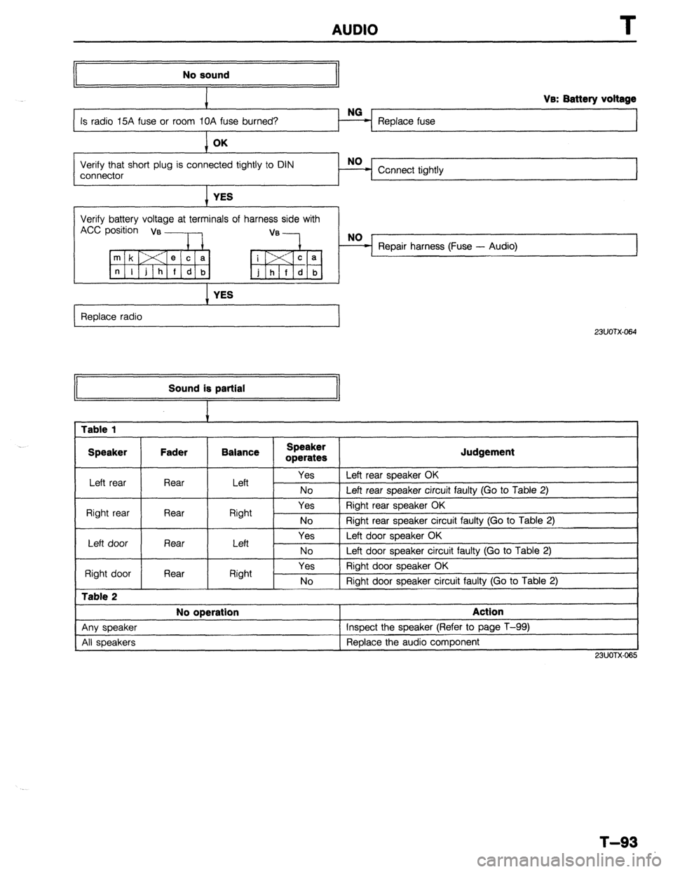
AUDIO
No sound
Replace fuse Va: Battery voltage
Verify that short plug is connected tightly to DIN
connector Connect tightly
I YES
Verify battery voltage at terminals of harness side with
Accp;;;ia, ,:---lb, “‘-k,
I YES
Replace radio
I
23UOTX-064 Sound is partial
1 Table 1
I Speaker Fader Balance
I Speaker
operates
I Judgement
Left rear Rear I Left Yes 1 Left rear speaker OK
No 1 Left rear soeaker circuit faulty (Go to Table 2)
Right rear Rear
I Right Yes Right rear speaker OK
No 1 Riaht rear sneaker circuit fauftv (Go to Table 2)
I
Left door
Right door
Table 2
Rear
Rear Left
Right Yes
No
Yes
No Left door speaker OK
Left door speaker circuit faulty (Go to Table 2)
Right door speaker OK
Right door speaker circuit faulty (Go to Table 2)
I No operation
I Action
I
1 Anv sneaker 1 Insoect the speaker (Refer to page T-99)
I
All speakers Replace the audio component
I
23UOTX.065
T-93
Page 950 of 1164
I
AUDIO
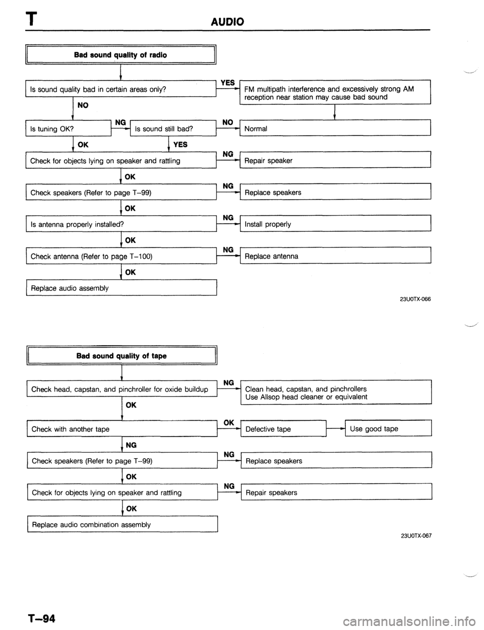
Bad sound quallty of radio
I
Is sound quality bad in certai
NO FM multipath interference and excessively strong AM
reception near station may cause bad sound
I
Is tuning OK?
I Normal t
Check for objects lying on speaker and rattling
I Repair speaker
1 OK
Check speakers (Refer to pa Replace speakers
1 OK
Is antenna properly installed?
I Install properly NO
Check antenna (Refer to page T-100) - Replace antenna L I L I OK
Replace audio assembly
23UOTX-066
II Bad sound quality of tape
II
Check with another tape Defective tape Use good tape
1 NG
Check speakers (Refer to page T-99)
I
Check for objects lying on speaker and rattling OK
I
I
Replace audio combination assembly
23UOTX.067
T-94
Page 951 of 1164
AUDIO
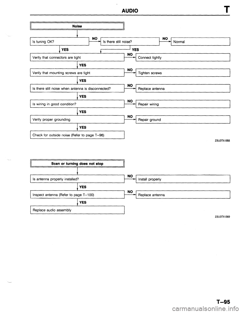
Noise
1 YES
I
Verify that mounting screws ar Tighten screws
1 YES
Is there still noise when anten
I Replace antenna YES
Is wiring in good condition? Repair wiring
I YES
Verify proper grounding Repair ground
I I YES
Check for outside noise (Refer to page T-96)
23UOTX-066 Scan or turning does not stop
Install properly
inspect antenna (Refer to p
, YES
Replace audio assembly
23UOTX-069
T-95
Page 952 of 1164
AUDIO
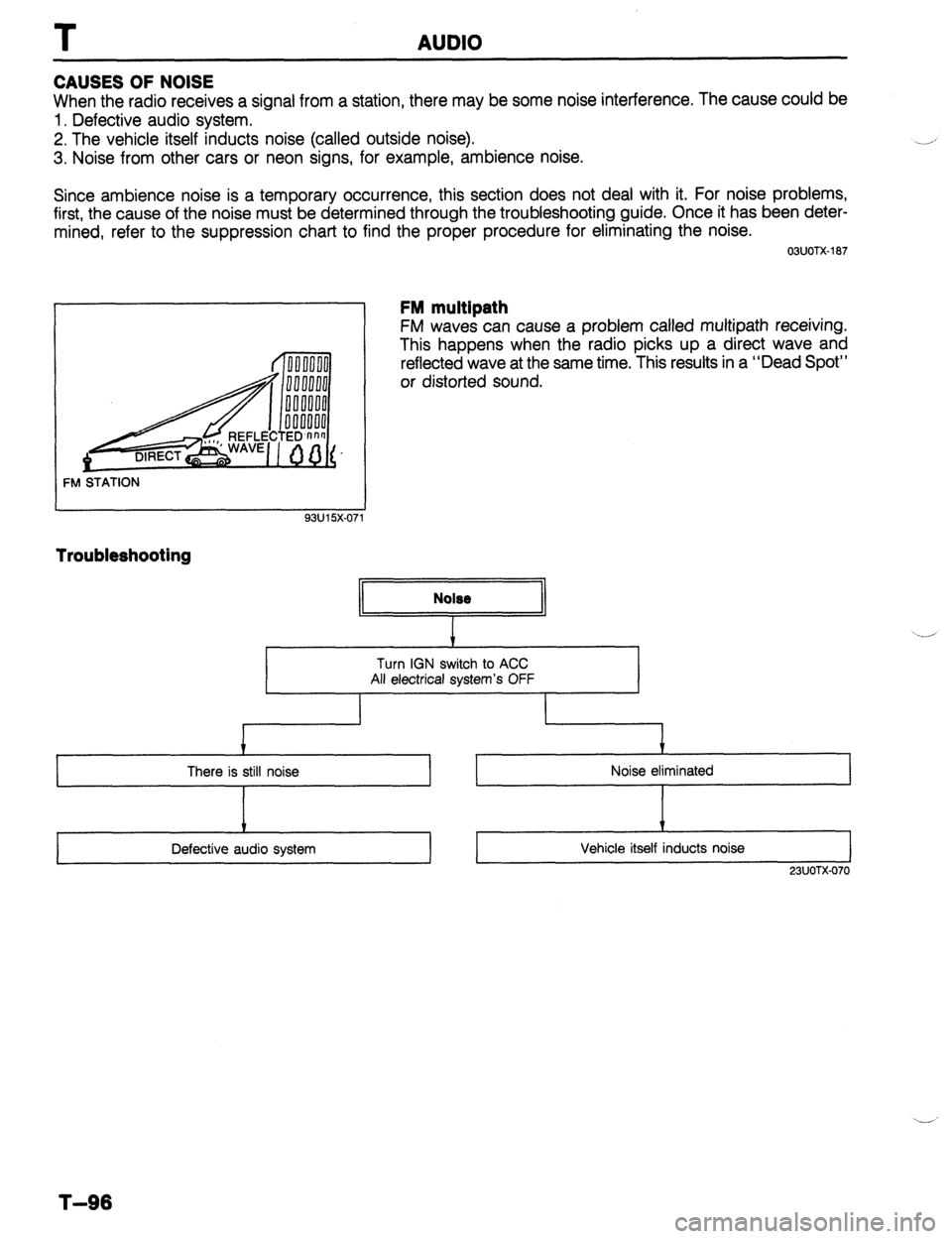
CAUSES OF NOISE
When the radio receives a signal from a station, there may be some noise interference. The cause could be
1. Defective audio system.
2. The vehicle itself inducts noise (called outside noise).
3. Noise from other cars or neon signs, for example, ambience noise.
Since ambience noise is a temporary occurrence, this section does not deal with it. For noise problems,
first, the cause of the noise must be determined through the troubleshooting guide. Once it has been deter-
mined, refer to the suppression chart to find the proper procedure for eliminating the noise.
FM STATION
93u15x-07 1 03UOTX-187
FM multipath
FM waves can cause a problem called multipath receiving.
This happens when the radio picks up a direct wave and
reflected wave at the same time. This results in a “Dead Spot”
or distorted sound.
Troubleshooting
I I
+
There is still noise
I
Defective audio system
+
Noise eliminated
V
Vehicle itself inducts noise
I
23UOTX-070
T-96
Page 953 of 1164

AUDIO T
Noise Suppression Chart
Cause
‘uel pump noise Remedy Move speaker wiring away from fuel pump wire.
REAR HARNESS FUEL
PUMP
Wotor noise
Wiper, washer, power
window, for example) 1. Check grounding.
2. Install condensers to motor circuit.
Turn signal noise Connect condenser (0.5 pF) to power line of filter unit. Note
CONDENSER
4lternator noise
l Condenser should be placed near flasher unit.
Connect condenser (0.5 pF) near alternator.
TO RADIO
CONDENSER
97UOTX-1
T-97
Page 954 of 1164
T AUDIO
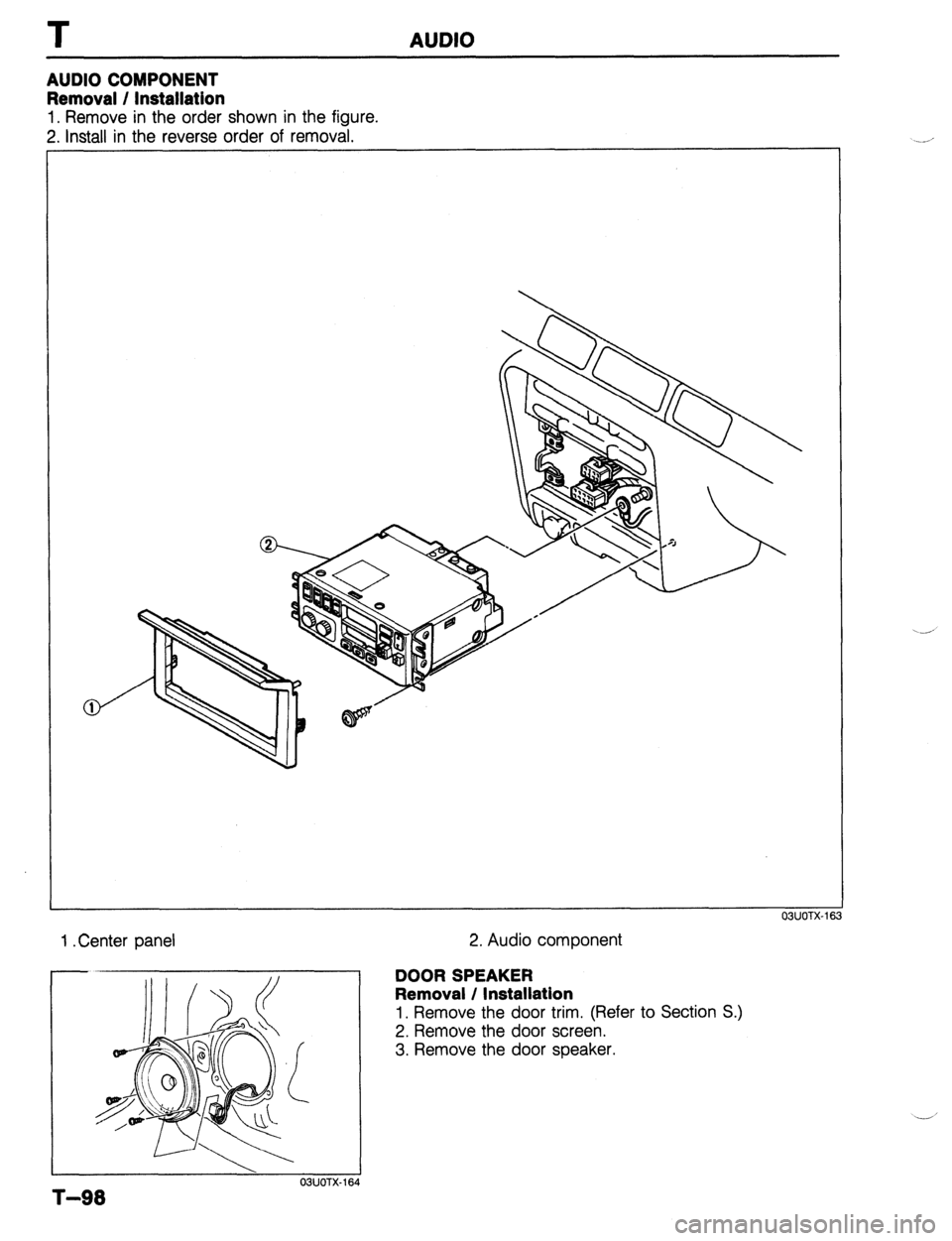
AUDIO COMPONENT
Removal / Installation
1. Remove in the order shown in the figure.
2. install in the reverse order of removal.
OBUOTX-163
1 .Center panel
T-98
03UOTX-1E
2. Audio component
DOOR SPEAKER
Removal / Installation
1, Remove the door trim. (Refer to Section S.)
2. Remove the door screen.
3. Remove the door speaker.
-’
Page 955 of 1164
AUDIO T
97UOTX-If
13UOTX-06
/-cl/ /
03UOTX-18:
03UOTX-16 OWOTX-189
6
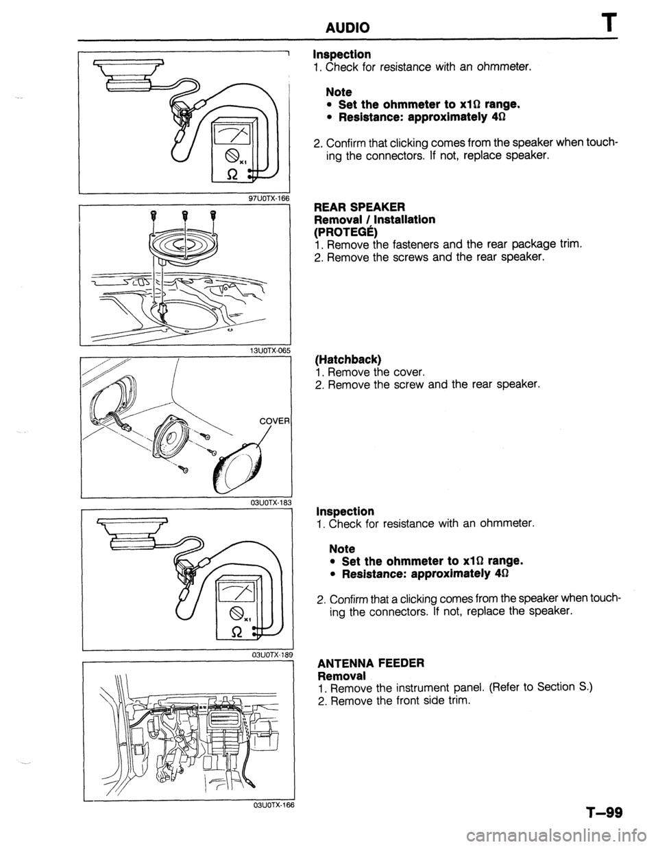
Inspection
1. Check for resistance with an ohmmeter.
Note
l Set the ohmmeter to xl0 range.
l Redstance: approximately 4h2
2. Confirm that clicking comes from the speaker when touch-
ing the connectors. If not, replace speaker.
REAR SPEAKER
Removal / Installation
(PROTEGe)
1. Remove the fasteners and the rear package trim.
2. Remove the screws and the rear speaker.
(Hatchback)
1. Remove the cover.
2. Remove the screw and the rear speaker.
Inspection
1. Check for resistance with an ohmmeter.
Note
l Set the ohmmeter to xl0 range.
l Resistance: approximately 43
2. Confirm that a clicking comes from the speaker when touch-
ing the connectors. If not, replace the speaker.
ANTENNA FEEDER
Removal
1. Remove the instrument panel. (Refer to Section S.)
2. Remove the front side trim.
T-99
Page 956 of 1164
T AUDIO
OWOTX-167
// 03UOTX-161
OBUOTX-
ANTENNA FEEDER
PLUG
OHMMETER
03UOTX-
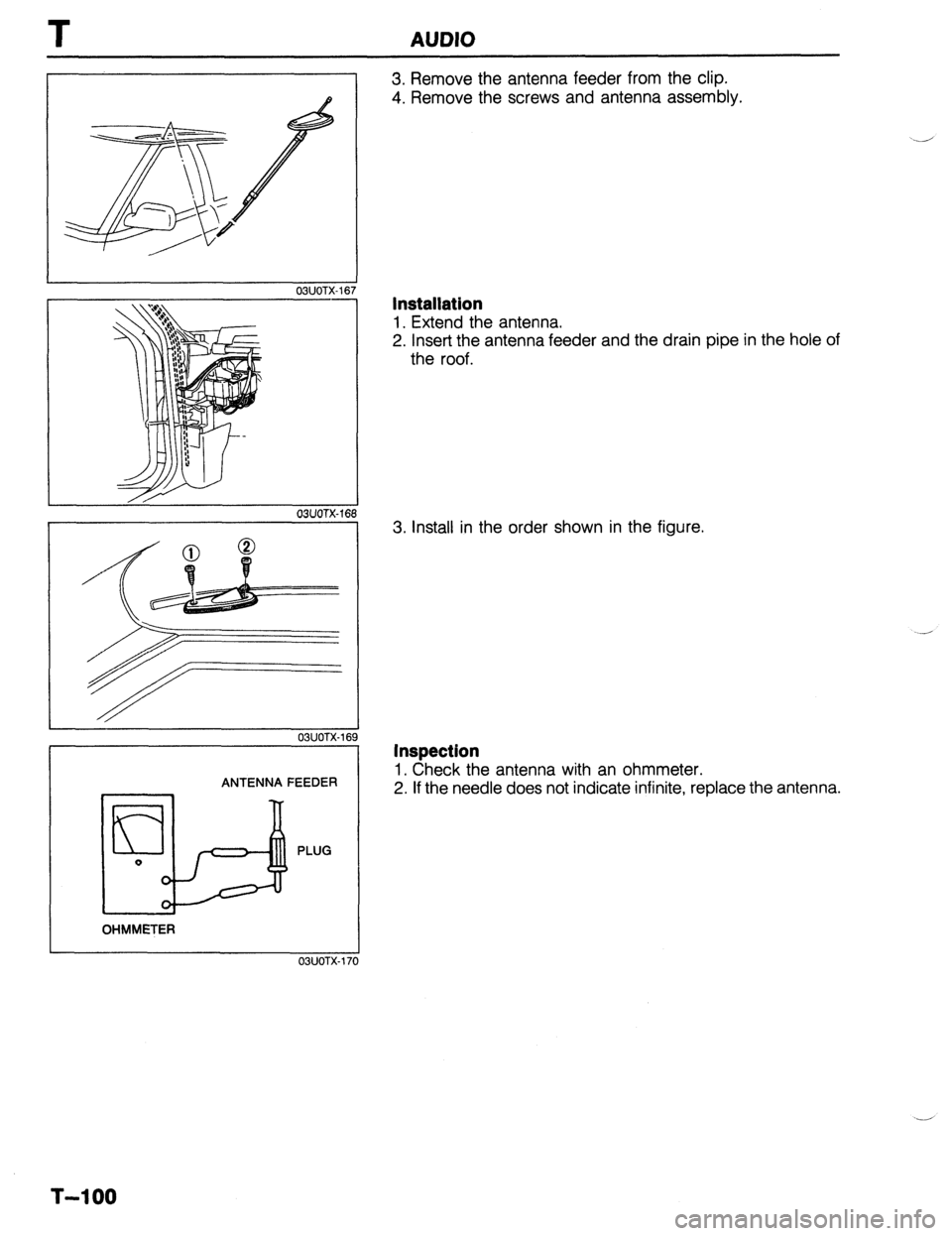
3. Remove the antenna feeder from the clip.
4. Remove the screws and antenna assembly.
Installation
1. Extend the antenna.
2. Insert the antenna feeder and the drain pipe in the hole of
the roof.
3. Install in the order shown in the figure.
Inspection
1. Check the antenna with an ohmmeter.
2. If the needle does not indicate infinite, replace the antenna.
T-l 00
Page 1024 of 1164

TD TECHNICAL DATA
G. ENGINE ELECTRICAL SYSTEM
3attery Dark
current*’
Alternator 86 SOHC BP SOHC
I BP DOHC
MTX 1 ATX 1 MTX 1 ATX
Voltage V 12
Type and capacity (20-hour rate) 55D23L (60AH) 1 55D23L (60AH)
mA Max. 20.0
Type A.C
output V-A 12-65
Regulator type Transistorized (built-in IC regulator)
Regulated voltage V 14.1-14.7
Brush length Standard 21.5 (0.846)
mm (in) Minimum 8.0 (0.315)
Drive belt deflection
New 8-Q (0.31-0.35)
;riL’F,i Used Q-10 (0.35-0.39)
Coaxial
Type Direct Direct Coaxial
reduction Direct
reductior
Starter output V-kW 12-0.85 12-0.95 12-1.4 12-0.95 12-1.4
Brush length Standard 17 (0.67) 17 (0.67) 17.5 (0.69) 17 (0.67) 17.5 (0.69
mm (in) Minimum 11.5 (0.453) 11.5 (0.453) 10.0 (0.39) 11.5 (0.453) 10.0 (0.39
Distributor Electronic spark advance (photo diode)
Ignition timing BTDC
(TEN terminal of diagnosis connector grounded) 6O-8O 4O-6O 9”-11 O
Ignition coil Resistance Primary coil winding 0.81 -O.QQg
(at 20% [68OF]) Secondary coil winding lo-16 kg
SK&E-1 1 BKR5E-11
NGK
BKRGE-11 BKRGE-11
BKR7E-11
Spark plug Type
NIPPONDENSO KlGPR-Ull
K20PRUll KlGPR-Ull
K20PRUll
K22PRUll *:
. Plug gap
Firing order mm (in) 1.0-l .l (0.039-0.043)
l-3-4-2
---
’ Dark current is the constant flow of current while the ignition switch IS UFF.
(i.e engine control unit, audio, etc.) ..-
._*
T&l 0
Page 1049 of 1164

PARTS INDEX
‘I
A
ACCELERATOR CABLE ............................. F-l 14
ACCELERATOR PEDAL ............................. F-l 14
AIR CONDITIONER ...................................... u-30
A/C RELAY.. ........................................... U-56
A/C SWITCH ...........................................
U-57
COMPRESSOR.. ..................................... U-41
CONDENSER.. ....................................... U-53
CONDENSER FAN ................................. u-57
CONDENSER FAN RELAY .................... U-56
COOLING UNIT ..................................... U-38
MAGNETIC CLUTCH ............................. u-51
RECEIVER/DRIER .................................. U-52
REFRIGERANT PRESSURE SWITCH.. .. U-55
AIR FLOW METER ..................................... F-l 68
AIR VALVE.. ................................................ F-l 16
ALTERNATOR .............................................. G-10
ANTENNA FEEDER
AUDIO
....... .......................................................................................... T-i;
AUTOMATIC TRANSAXLE ............................. K-l
2-4 BRAKE BAND ................................ K-l 97
3-4 CLUTCH.. ....................................... K-l 87
ACCUMULATORS ................................ K-l 67
ATF ....................................................... K-135
ATF THERMOSENSOR ........................ K-142
BEARING COVER ASSEMBLY ............ K-208
CLUTCH ASSEMBLY ........................... K-l 72
CONTROL VALVE BODY.. .....
K-21 0,224,234
DIFFERENTIAL ..................................... K-236
DRIVE PLATE.. ..................................... K-267
EC-AT CONTROL UNIT ....................... K-144
HOLD SWITCH ..................................... K-140
HYDRAULIC CIRCUIT .......................... K-278
IDLER GEAR ........................................ K-203
INHIBITOR SWITCH ............................. K-l 41
LOW AND REVERSE BRAKE .............. K-192
MAIN CONTROL VALVE BODY .......... K-220
OIL COOLER.. ...................................... K-265
OIL PUMP ............................................
K-169
OIL SEAL ..............................................
K-209
ONE-WAY CLUTCH 2
CARRIER HUB ASSEMBLY ............... K-185
OUTPUT GEAR .................................... K-206
P RANGE SWITCH.. ............................. K-271
PREMAIN CONTROL VALVE BODY .a. K-218
PULSE GENERATOR ........................... K-142
SELECTOR LEVER ............................... K-272
SHIFT MECHANISM ............................. K-269
SHIFT-LOCK ACTUATOR
..................... K-271
SMALL SUN GEAR AND
ONE-WAY CLUTCH 1 ........................ K-l 82
SOLENOID VALVE.. ............................. K-l 43
SPEEDSENSOR .................................. K-l 43
THROTTLE CABLE .............................. K-l 37
TORQlJE CONVERTER.. ...................... K-l 66
TRANSAXLE UNIT. ......... K-149,153,246,261 UPPER CONTROL VALVE BODY.. ..... K-215
BACK-UP LIGHT SWITCH..
..........................
BATTERY T;4;
- .......................................................
BLOWER UNIT ............................................
U-23
BRAKE FLUID.. .............................................. P-8
BRAKE MASTER CYLINDER. ...................... P-10
BRAKE PEDAL ...............................................
P-8
C
CALIPER .................................................. P-21,26
CARGO COMPARTMENT LAMP ................. T-54
CENTRAL PROCESSING UNIT..
.................. T-55
CHARCOAL CANISTER ............................. F-l 41
CHECK VALVE (TWO-WAY) .......................
CHECK-AND-CUT VALVE - .......................... ;-;b$
CIRCUIT OPENING RELAY.. ...................... F-129
CLUTCH COVER ......................................... H-l 7
CLUTCH DISC ............................................. H-l 7
CLUTCH FLUID ............................................. H-4
CLUTCH MASTER CYLINDER.. .................... H-7
CLUTCH PEDAL ............................................ H-5
CLUTCH RELEASE CYLINDER..
................. H-12
CLUTCH SWITCH (MTX) ............................ F-l 72
COMBINATION SWITCH .............................. T-23
COWL GRILLE ............................................. S-53
CRUISE CONTROL UNIT.. ...................... T-78,85
D
DASHBOARD ............................................... S-94
DASHPOT ................................................... F-l 42
DISTRIBUTOR .............................................. G-20
DOOR LOCK TIMER UNIT ........................... T-17
DOOR MIRROR ............................................ S-54
REMOTE CONTROL MIRROR ............... S-56
REMOTE CONTROL MIRROR SWITCH. S-55
DOOR SPEAKER .......................................... T-98
DRIVE SHAFT.. ....................................... M-l 7,21
DRL RELAY.. ................................................ T-18
DRL RESISTOR ............................................ T-46
DUAL PROPORTIONING VALVE..
............... P-l 6
DYNAMIC CHAMBER ................................ F-l 12
E
ELECTRIC COOLING FAN SYSTEM ........... E-13
ENGINE (B6 & BP SOHC) ........................... Bl-2
CAMSHAFT ..........................................
Bl-58
CAMSHAFT PULLEY ...........................
Bl-65
CONNECTING ROD ............................. 81-63
PI-I