MAZDA PROTEGE 1992 Workshop Manual
Manufacturer: MAZDA, Model Year: 1992, Model line: PROTEGE, Model: MAZDA PROTEGE 1992Pages: 1164, PDF Size: 81.9 MB
Page 281 of 1164

OUTLINE F
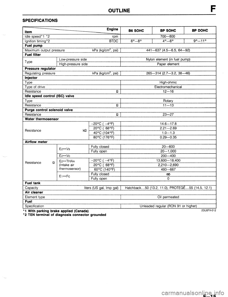
SPECIFICATIONS
Item
Idle speed*1 *2
Ignition timing*2
Fuel pump
Maximum outout Dressure Engine
rpm B6 SOHC
6O--80 BTDC 1
kPa (ka/cm’. osi1 1 BP SOHC
700-800
4O---6O BP DOHC
90-l 1 O
441-637 (4.5-6.5. 64-92) I
I Fuel filter I
Type Low-pressure side Nylon element (in fuel pump)
High-pressure side Paper element
Pressure reaulator
Regulating pressure kPa (kg/cm’, psi) 1 265-314 (2.7-3.2, 38-46)
I lniector I
Type Type of drive
Resistance
Idle speed control (ISC) valve
TvDe , ,
t Resistance
Purge control solenoid valve
Resistance
Water thermosensor n High-ohmic
Electromechanical
12-16
Rotarv
n I II-13 I
n 1 23-27
1 -20% I -4OFj 1 14.6-17.8
Resistance k62 2ooc i 68OF) 2.21-2.69
40°C (104OF) 1.0-l .3
80°C (176OF) 0.29-0.35
Airflow meter
E2++Vs
E2-Vc Fully closed
Fully open 20-600
20-l ,000
200-400
Capacity liters (US gal, Imp gal) 1 Hatchback 50 (13.2, ll.O), PROTEGE ,... 55 (14.5, 12.1)
I Air cleaner I
Element type
Fuel
Specification l
l Wlth parking brake applied (Canada)
‘2 TEN terminal of diagnosis connector grounded Oil permeated
Unleaded regular (RON 91 or higher) 23UOFX-012
F-l 5
Page 282 of 1164

F OUTLINE
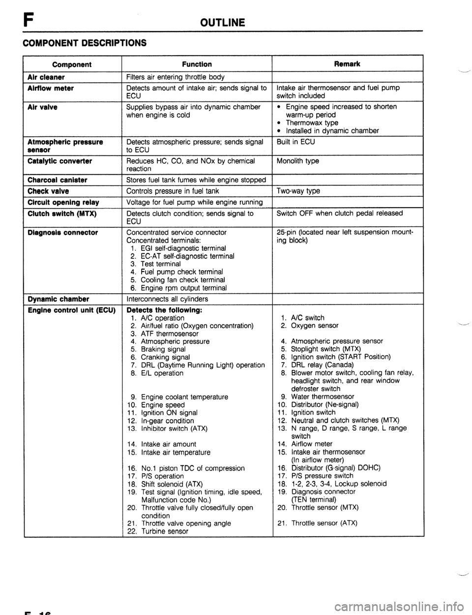
COMPONENT DESCRIPTIONS
Component
Air cleaner
Airflow meter
Mr valve
Atmospheric pressure
Sensor
Catalytic converter Function Remark
Filters air entering throttle body
Detects amount of intake air; sends signal to intake air thermosensor and fuel pump
ECU switch included
Supplies bypass air into dynamic chamber
l Engine speed increased to shorten
when engine is cold warm-up period
l Thermowax type l Installed in dynamic chamber
Detects atmospheric pressure; sends signal Built in ECU
to ECU
Reduces HC, CO, and NOx by chemical Monolith type
reaction Charcoal canister
Stores fuel tank fumes while engine stopped Check valve
Controls pressure in fuel tank Two-way type Circuit opening relay
Voltage for fuel pump while engine running Clutch switch (MTX)
Detects clutch condition; sends signal to Switch OFF when clutch pedal released
ECU Diagnosis connector
Concentrated service connector 25pin (located near left suspension mount-
Concentrated terminals: ing block)
1. EGI self-diagnostic terminal
2. EC-AT self-diagnostic terminal
3. Test terminal
4. Fuel pump check terminal
5. Cooling fan check terminal
6. Engine rpm output terminal Dynamic chamber
Interconnects all cylinders Engine control unit (ECU) Detects the following:
1. A/C operation 1. A/C switch
2. Air/fuel ratio (Oxygen concentration) 2. Oxygen sensor
3. ATF thermosensor
4. Atmospheric pressure 4. Atmospheric pressure sensor
5. Braking signal 5. Stoplight switch (MTX)
6. Cranking signal 6. Ignition switch (START Position)
7. DRL (Daytime Running Light) operation 7. DRL relay (Canada)
8. E/L operation 8. Blower motor switch, cooling fan relay,
headlight switch, and rear window
defroster switch
9. Engine coolant temperature 9. Water thermosensor
10. Engine speed 10. Distributor (Ne-signal)
11. Ignition ON signal 11. Ignition switch
12. In-gear condition 12. Neutral and clutch switches (MTX)
13. Inhibitor switch (ATX) 13. N range, D range, S range, L range
switch
14. Intake air amount 14. Airflow meter
15. Intake air temperature 15. Intake air thermosensor
(In airflow meter)
16. No.1 piston TDC of compression
17. P/S operation
18. Shift solenoid (ATX)
19. Test signal (Ignition timing, idle speed,
Malfunction code No.)
20. Throttle valve fully closed/fully open
condition 16. Distributor (G-signal) DOHC)
17. P/S pressure switch
18. 1-2, 2-3, 3-4, Lockup solenoid
19. Diagnosis connector
(TEN terminal)
20. Throttle sensor (MTX)
21. Throttle valve opening angle
22. Turbine sensor 21. Throttle sensor (ATX) .__r
F-10
Page 283 of 1164

OUTLINE
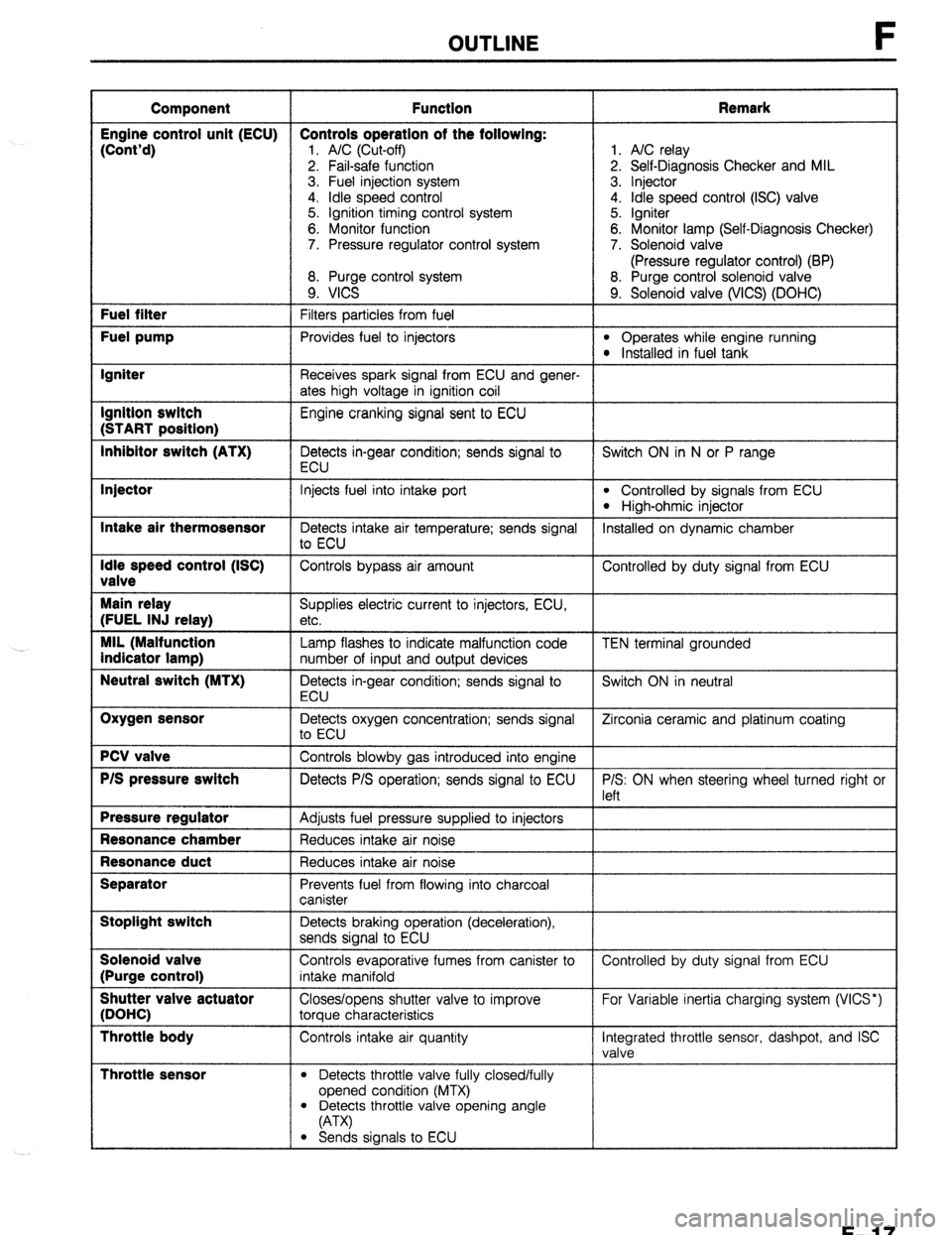
Component Function Remark
Engine control unit (ECU) Controls operation of the following:
(Cont’d)
1. A/C (Cut-off) 1. A/C relay
2. Fail-safe function 2. Self-Diagnosis Checker and MIL
3. Fuel injection system 3. Injector
4. idle speed control 4. Idle speed control (ISC) valve
5. Ignition timing control system 5. Igniter
6. Monitor function 6. Monitor lamp (Self-Diagnosis Checker)
7. Pressure regulator control system 7. Solenoid valve
(Pressure regulator control) (BP)
8. Purge control system 8. Purge control solenoid valve
9. VICS 9. Solenoid valve (WCS) (DOHC) Fuel filter
Filters particles from fuel Fuel pump
Provides fuel to injectors l Operates while engine running l Installed in fuel tank Igniter
Receives spark signal from ECU and gener-
ates high voltage in ignition coil Ignition switch
Engine cranking signal sent to ECU (START position)
Inhibitor switch (ATX)
Detects in-gear condition; sends signal to Switch ON in N or P range
ECU Injector
Intake air thermosensor
Idle speed control (ISC)
valve
Main relay
(FUEL INJ relay)
MIL (Malfunction
indicator lamp)
Neutral switch (MTX)
Oxygen sensor
PCV valve
P/S pressure switch
Pressure regulator
Resonance chamber
Resonance duct
Separator
Stoplight switch
Solenoid valve
(Purge control)
Shutter valve actuator
(DOHC)
Throttle body
Throttle sensor
Injects fuel into intake port l Controlled by signals from ECU
l High-ohmic injector
Detects intake air temperature; sends signal Installed on dynamic chamber
to ECU
Controls bypass air amount Controlled by duty signal from ECU
Supplies electric current to injectors, ECU,
etc.
Lamp flashes to indicate malfunction code
number of input and output devices
Detects in-gear condition; sends signal to
ECU
Detects oxygen concentration; sends signal
to ECU
Controls blowby gas introduced into engine
Detects P/S operation; sends signal to ECU
Adjusts fuel pressure supplied to injectors
Reduces intake air noise
Reduces intake air noise
Prevents fuel from flowing into charcoal
canister
Detects braking operation (deceleration),
sends signal to ECU
Controls evaporative fumes from canister to
intake manifold
Closes/opens shutter valve to improve
torque characteristics
Controls intake air quantity
l Detects throttle valve fully closed/fully
opened condition (MTX) TEN terminal grounded
Switch ON in neutral
Zirconia ceramic and platinum coating
P/S: ON when steering wheel turned right or
left
Controlled by duty signal from ECU
For Variable inertia charging system (VICS*)
Integrated throttle sensor, dashpot, and ISC
valve
l Detects throttle valve opening angle
(A-W
l Sends signals to ECU
F-l 7
Page 284 of 1164

F OUTLINE
I Component
I Function
I Remark
I
Three-way
solenoid
valve vIcs*
Pressure
regulator
control
Controls vacuum to shutter valve actuator
Controls vacuum to pressure regulator Cuts vacuum when engine speed above
5.000 ram
Cuts vacuum just after starting when engine
hot starting Vacuum chamber
(DOHC)
Water thermosensor
Stores vacuum for use during wide open For WCS*
throttle
Detects coolant temperature; sends signal to
ECU
l WCS: Variable Inertia Charging System 23UOFX-013
F-l 8
Page 285 of 1164

OUTLINE F
MEMO
F-19
Page 286 of 1164

F TROUBLESHOOTING GUIDE
TROUBLESHOOTING GUIDE
ENGINE CONTROL OPERATION CHART
Note
Input Device and Engine Conditions
l The data in this chart is for reference only.
INPUT DEVICES APPROX,- SENSORS
MATE TIME G& THROTTLE SENSOR
(BASED ON TRIBUTOR
WATER INTAKE
10-16°C, (G. OXYGEN AIRFLOW AIR
VT
POW
.50-6OOF
SIGNAL)” ;;;;;f- SENSOR METER
AMBIENT) (Ne-SIGNAL) THERMO- TERMINAL TERMINAL yE\MINAL
CONDITIONS SENSOR (ATX)
WX)
A
c
CRANKING
-COLD ENGINE Signal has Signal has Signal has Signal has Slgnal has Slgnal has
l COLD AIR zero no affect no effect no effect no effect no effect
no effect
. COLD COOLANT on ECU on ECU on ECU on ECU on ECU
on ECU
Cool to A A
COLD START
warm: Low volume Closed Closed
Closed
-FAST IDLE
One
Medium airflow: throttle: throttle:
l COLD AIR
minute
voltage High volt-
Low volt- Low volt- throttle.
Low volt-
* COLD COOLANT
(3.5” and :zo:o, ,,Pbove 1’,“,“$; a(ogi-O,8”) ;149&“) we W)
dropping) to high
(68OF)]:
COLD DRIVEAWAY voltage A
Above
-PART THROTTLE Two (O-0.9”) 2.3”
l COLD AIR minutes
l COLD COOLANT
v v ,,
Warm: Medi- Sensor Moderate II
WARM DRIVEAWAY
volume air-
-PART THROTTLE Three N&IGNAL um voitage hot:
flow: Low
l WARM AIR minutes Sends all Vvwrox switching l WARM COOLANT cylinders 0.7V and
from high to medium
Part Part
TDC signal dropping) voltage voltage
throttle: throttle.
)
A (0.9V) (1 .o-3.5”)
to ECU
.“~ Medium Medium
HOT CRUISE
s voltage voltage
Open
l WARM AIR G-
SIGNAL”’ to low (0.8-3.0”) (4.5-5.5”) throttle:
l WARM COOLANT High
Sends No. voltage
1 cylinder (0.1”) voltage
1 (battery
TDC (com-
1 I voltage)
HOT ACCELERATION pression)
-60% THROTTLE signal to
Moderate
ECU
to strong
High Cool lo warm
voltage ;$,“,” Of j-20-4OT
f t
HOT ACCELERATION
More’ than Hot: Low (0.9”) Low (-4-‘04”F)l: W,ds open
voltage 1.5-4.3v
throttle: Wide open
-WIDE OPEN
four voltage
High volt- throttle
THROTTLE (0.5-1.5V)
minutes (Below High
0.5”) age (Above
voltage (OV)
t 1 3.OV)
I,
A 1. /I
DECELERATION
-CLOSED THROTTLE
HOT CURB IDLE
-EXTENDED
HOT ENGINE
SHUTDOWN Low
voltage
(0”) Low Closed Closed
Closed
volume throttle: throttle.
throttle.
of airflow:
~~~~!$$ (Above Low Low
Low
voltage voltage
voltage
to low 3.OV) (0.2-0.N) (4.5-5 5V) (OV)
voltage
(0.75%
t t 1 0.25”)
r v 1 I I
Sensor
hot: Low
OFF OFF voltage
-
(0.1”) until OFF OFF OFF OFF
OFF
sensw
COOIS
._-
Page 287 of 1164
![MAZDA PROTEGE 1992 Workshop Manual TROUBLESHOOTING GUIDE F
r
- SENSORS
z-----
‘RES-
‘URE
‘WITCH FRL (Dsy
ime Run-
ling
.ight)
:ONTROL
INIT
CANADA]
)FF
3attery
oltage)
T- IEUTRAL
rND
:LUTCH
iWITCHES
MTX) IIAGNO MAZDA PROTEGE 1992 Workshop Manual TROUBLESHOOTING GUIDE F
r
- SENSORS
z-----
‘RES-
‘URE
‘WITCH FRL (Dsy
ime Run-
ling
.ight)
:ONTROL
INIT
CANADA]
)FF
3attery
oltage)
T- IEUTRAL
rND
:LUTCH
iWITCHES
MTX) IIAGNO](/img/28/57077/w960_57077-286.png)
TROUBLESHOOTING GUIDE F
r
- SENSORS
z-----
‘RES-
‘URE
‘WITCH FRL (Dsy
ime Run-
ling
.ight)
:ONTROL
INIT
CANADA]
)FF
3attery
oltage)
T- IEUTRAL
rND
:LUTCH
iWITCHES
MTX) IIAGNOSIS
:ONNEC-
‘OR TEN
‘ERMINAL
rEST
‘ERMINAL) IGNITION SWITCH
s kgnal has
r IO effect
C In ECU
I neutral:
.ow volt-
rge signal
II ECU
w
-
f
I
Iriving in
iny gear:
iigh volt-
ige signal
o ECU
Battery TOP-
IGHT
WITCH UHIBITOR
iWITCH
4TX) L/C
;WITCH
5
IL
IGNAL
Sl ignal has
nl 3 effect
01 n ECU
H
0
F-f
S
C
VI
si
E
te
VI
C
VI
si
i
1 T
eadlight
r rear
‘indow
efroster
Nitch
IN: High
pltage
gnal to
CU (Bat-
try
sltage)
IFF: Low
altage
gnal to
cu
3elow
.5V)
B
S'
0
C,
C
L
E
E
II
(
\i
c
E
t’
I lower
Nitch**
r Electri-
al fan
IN: Low
foltage
signal to
iCU (Be-
3w 1.W)
IFF: High
loltage
rignal to
ICU (Bat-
ev
voltage)
I
OFF ITART
‘OSITION IN
OSITION
‘ends sig
al to
CU (Bat-
?ry
oltage) #ignal has
0 effect
#n ECU ignal has
0 effect
n ECU ignal has
0 effect
n ECU ;ignal has
IO effect
rn ECU ignal has
0 effect
n ECU
rake pedal Ggnal has
IQ effect
In ECU
1NorP
ange: No
ignal to
.cu
w
-
7D
ange: No
#ignal to
.cu
Battery
foltage)
- - - - -
ends sig-
31 to ECU
jattr ?ry
Atac
-2
/heel -
Jrned:
ow volt-
ge signal
I ECU
3elow
.5V)
teering
/heel
traight
head:
ligh volt-
ge signal
) ECU
dattery .erminal
lot
Irounded:
iigh volt-
tge Signal
3 ECU
Battery
roltage)
‘erminal
Irounded:
.ow volt-
rge signal
3 ECU
Below lo signal
ent to
cu
3elow
5V) r/C switch
IN:
iends sig-
ial to
CU (Be-
IW 1.5V)
r/C switch
IFF: No
ignal to
CU (Bat-
3ry
‘oltage) )RL ON:
w ends sig-
al to
CU (Bat-
2ry
oltage) lo signal
3 ECU
3elow
.5V) )RL OFF:
3attery
oltage)
I .5V’
medal
Sends
signal to
KU
Battery
voltage)
- -
In N or P
range:
Sends sig-
nal to ECU
PV In neutral:
Low volt-
age stgnal
to ECU
(W
I -
- - -
OFF OFF OFF OFF OFF OFF OFF
OFF OFF
23UOFX-0’
+’ Blower switch: 2nd position or more
F-21
Page 288 of 1164

F TROUBLESHOOTING GUIDE
Output Devices and Engine Conditions
Note
. The data in this chart is for reference only.
INJECTOR
CONDITIONS
CRANKING
-COLD ENGINE
l COLD AIR l COLD COOLANT
COLD START
-FAST IDLE
l COLD AIR l COLD COOLANT
COLD DRIVEAWAY
-PART THROTTLE
l COLD AIR l COLD COOLANT
WARM DRIVEAWAY
-PART THROTTLE
. WARM AIR
l WARM COOLANT
HOT CRUISE
l WARM AIR l WARM COOLANT Zero
One
mrnute
Two
minutes
Three
minutes
I AIR
INJECTION “AL”E
INJECTION TlMlNG
A
All A
cylinders
each
ignition
pulse
1
Rich Open:
coolant
tem-
perature:
Below
40%
(104OF)
,
I/
Rich and
2-group” 1’
lean l-group” /I
,
i
HOT ACCELERATION
-60% THROTTLE
-lOT ACCELERATION
-WIDE OPEN
THROTTLE
Closed ISC
VALVE
1, THREE-WAY
SOLENOID SOLENOID
VALVE VALVE
(PURGE
(PRESSURE
CONTROL) REGULATOR
CONTROL)‘3
c
OFF
(Purge
cut)
Large
1
, AK
RELAY
amount or
bypass air
OFF
(Vacuum
to
pressure
regulator)
After start-
rng: ON dur-
ing hot start
only (Vacu-
um cut)
OFF
l 2 SOHC, *’ BP
F-22
Page 289 of 1164

TROUBLESHOOTING GUIDE F
THREE-
WAY
SOLE-
NOID
VALVE
(WCS)”
ON
(Vacuum
to shutter
valve
actuator)
A
Engine
speed
below
5,000
rpm:
3FF
(Vacuum
wt)
I
3N
:Vacuum
:o shutter
Jalve
actuator)
OFF
23UOFX-01
F-23
Page 290 of 1164

F TROUBLESHOOTING GUIDE
RELATIONSHIP CHART
OUTPUT DEVICE
INPUT DEVICE
DIAGNOSIS CONNECTOR
[TEN TERMINAL) 0 0 0 0
IGNITION SWITCH (START POSITION) 0 0 0 0 0 0
E/L SIGNALg4 0
0
P/S PRESSURE SWITCH 0 0
B/C SWITCH 0 0 0
INHIBITOR SWITCH (ATX) 0 0 0 0 0 0 0
NEUTRALANDCLUTCH
SWITCHES (MTX) 0 0 0 0 0 0 0
STOPLIGHT SWITCH 0
0
&TMOSPHERIC PRESSURE SENSOR
[IN ECU) o 0 0 0 0
rHROTTLE SENSOR 0 0 0 0 0 0 0
INTAKE AIR THERMOSENSOR 0 0 0 0 0
MRFLOW METER 0 0 0 0 0
3XYGEN SENSOR 0 0 0 0
JVATERTHERMOSENSOR 0 0 0 0 0 0 0
G-SIGNAL*’ 0 0
3ISTRIBUTOR
Ne-SIGNAL 0 0 0 0 0 0 0 0
-- ,.-, ,--., ,.*
+z
*3 &HC
MIL: Malfunction Indicator Lamp
r.9u”rn-” I
*’ E/L SIGNAL: Blower fan control switch second position or higher, cooling fan operating, headlights ON, or rear win-
dow defroster switch ON
F-24