MAZDA PROTEGE 1992 Workshop Manual
Manufacturer: MAZDA, Model Year: 1992, Model line: PROTEGE, Model: MAZDA PROTEGE 1992Pages: 1164, PDF Size: 81.9 MB
Page 431 of 1164

CONTROL SYSTEM F
Incorrect voltage
Above OV
Always OV
Always VB
Always Va
Always OV
Always Ve
Always OV
Always VB
Always approx. OV or VB -
-
-
Always OV or Ve -
-
-
Always OV or Vs -
-
- Possible cause
VB: Battery voltage
l Poor connect at ground terminal l Open circuit in wiring from ECU to ground
l Inhibitor switch malfunction (Refer to page K-141) l Short circuit in wirina from inhibitor switch to ECU terminal 3E
l Inhibitor switch malfunction (Refer to page K-141)
. Open circuit in wiring from inhibitor switch to ECU terminal 3E
l Short circuit in wiring from DRL relay to ECU terminal IL l Short circuit in wiring from DRL relay to DRL unit
l Open circuit in wiring from DRL relay to ignition switch
l Parking brake switch always ON l DRL unit malfunction (Refer to page T-33)
l Inhibitor switch malfunction (Refer to page K-141) l Short circuit in wiring from inhibitor switch to ECU terminal 3G
l Inhibitor switch malfunction (Refer to page K-141) l Short circuit in wiring from inhibitor switch to ECU terminal 3G
l Inhibitor switch malfunction (Refer to page K-141) l Short circuit in wiring from inhibitor switch to ECU terminal 3H
l Inhibitor switch malfunction (Refer to page K-141) l Open circuit in wiring from inhibitor switch to ECU terminal 2H
l Refer to Code No.41 Troubleshooting (Refer to page F-103) -
-
-
l Refer to Code No.25 Troubleshooting (Refer to page F-102) -
-
-
l Refer to Code No.34 Troubleshooting (Refer to page F-103) -
-
F-l 65
Page 432 of 1164

F CONTROL SYSTEM
Ve: Battery voltage
erminal Input Output
Connection to Test condition Correct voltage Remark
3u 0 Injector (Nos. 1, 3) Ignition switch ON VB * Engine Signal
Idle Va Monitor: Green
and red lamps
Engine speed above 2,000 rpm on de- Va
flash
celeration (After warm-up)
3v 0 Injector (Nos. 2, 4) ignition switch at idle
VB
Idle VB
Engine speed above 2,000 rpm on de-
VB
celeration (After warm-up)
3W 0 1-2 shift solenoid Solenoid valve ON i&I AT running
valve
Solenoid valve OFF ov
3x 0 2-3 shift solenoid Solenoid valve ON
VB AT running
valve
Solenoid valve OFF ov
3Y 0
ZH;hift solenoid Solenoid valve ON VB AT running
Solenoid valve OFF ov
32 0 Lockup solenoid Solenoid valve ON
VB AT running
valve
Solenoid valve OFF ov
23UOFX-1~
1 I u- l-1 ,
III h-3
I r
3y 13W 13U (3Sl3Cj3+4]3K 31 13Gj3EI 3C 13A 2012h42Kl21 12Gl2E12Cj2A 1 U 11 SllC$O 1 MI1 K 1 I 11 G 1 El 1 C 11 A
32 )3X I3Vj3Tj3R]3Pj3N]3L 3Jj3Hj3F13D 138 2P)2N)2L~2J~2H~2F~2D~2B 1V IlTjlRjlP 1NjlL 1JjlH 1FI lD\lB
-*’
.J’ -
F-l 66
Page 433 of 1164

CONTROL SYSTEM
Ve: Betterv voltaae
Incorrect voltage Possible csuse
Always OV l Main relay (FUEL INJ relay) malfunction (Refer to page F-172) l Open or short circuit in wiring from injector to ECU terminal 3U or 3V
Always Ve
l ECU malfunction
Always OV
Always Ve
l 1-2 shift solenoid valve malfunction (Refer to page K-143) l Short circuit in wiring from solenoid valve to ECU terminal 3W
I
l l-2 shift solenoid valve malfunction (Refer to page K-143) l Ooen circuit in wiring from solenoid valve to ECU terminal 3W
Always OV
l 2-3 shift solenoid valve malfunction (Refer to page K-143) l Short circuit in wirino from solenoid valve to ECU terminal 3X
Always VB
Always OV
l 2-3 shift solenoid valve malfunction (Refer to page K-143) l Open circuit in wiring from solenoid valve to ECU terminal 3X
l 3-4 shift solenoid valve malfunction (Refer to page K-143) l Short circuit in wiring from solenoid valve to ECU terminal 3Y
Always
VB l 3-4 shift solenoid valve malfunction (Refer to page K-143) l Open circuit in wiring from solenoid valve to ECU terminal 3Y
Always OV
l Lockup solenoid valve malfunction (Refer to page K-143) l Short circuit in wiring from solenoid valve to ECU terminal 32
Always Ve
l Lockup solenoid valve malfunction (Refer to page K-143) l Open circuit in wiring from solenoid valve to ECU terminal 32
23UOFX-1 E i0
F-l 67
Page 434 of 1164

F CONTROL SYSTEM
23UOFX-l! 51
.
r---- - --------1
I
I
i I
I
:,
m7 I
- - -.-
Fc E, Vc Ez 23UOFX-158
WATER THER@OSENSOA
I
03UOFX-21
REPLACE WASHEF
f
OYJOFX-2’
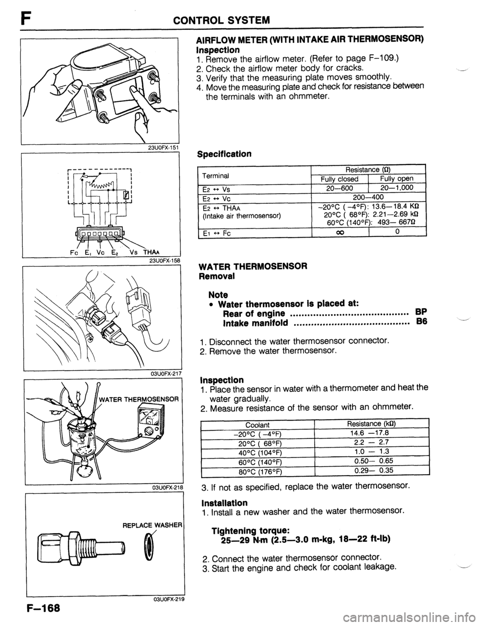
AIRFLOW METER (WITH INTAKE AIR THERMOSENSOR)
Inspection
1. Remove the airflow meter. (Refer to page F-109.)
2. Check the airflow meter body for cracks.
3. Verify that the measuring plate moves smoothly.
4. Move the measuring plate and check for resistance between
the terminals with an ohmmeter.
Specification
Terminal
E2 * Vs
E2 ++ Vc
E2
* THAA
(Intake air thermosensor)
El +, Fc Resistance (0)
Fully closed 1
Fully open
20-600 1 20-l ,000
200-400
-20% ( -4’=F): 13.6- 18.4 KQ
20% ( 6899 2.21-2.69 kD
60°C (14OOF): 493- 6670
00
0
WATER THERMOSENSOR
Removal
Note
l Water thermosensor Is placed at:
Rear of engine . . . . . . . . . . . . . . . . . . . . . . . . ..*.............. BP
Intake manifold ,.*......,..m...,..,.....*....*......... 86 -’
1. Disconnect the water thermosensor connector.
2. Remove the water thermosensor.
Inspection
1. Place the sensor in water with a thermometer and heat the
water gradually.
2. Measure resistance of the sensor with an ohmmeter.
3. If not as specified, replace the water thermosensor.
lnstallatlon
1. Install a new washer and the water thermosensor.
Tlghtening torque:
25-29 N.m (2.5-3.0 m-kg,
18-22 ft-lb)
2. Connect the water thermosensor connector.
3. Start the engine and check for coolant leakage.
F-l 68
Page 435 of 1164

CONTROL SYSTEM F
03UOFX-22
RESISTANCE
WI
THROTTLE VALVE
OPENING ANGLE
FULLY bPEN
03UOFX-22
03UOFX-2i
THROTTLE SENSOR
Inspection (MTX)
1. Disconnect the connector from the throttle sensor.
2. Connect an ohmmeter to the throttle sensor.
3. Insert a feeler gauge between the throttle stop screw and
the stop lever and check the continuity between terminals.
Feeler gauge Continuity between terminals
IDL - E
1 POW * E
O.lmm (0.004 in)
1 .Omm (0.039 in)
Wide-open throttle Yes
No
No No
No
Yes
Inspection (ATX)
1. Disconnect the connector from the throttle sensor.
2. Connect an ohmmeter between the throttle sensor termi-
nals E and IDL.
3. Insert a feeler gauge between the throttle stop screw and
the stop lever.
4. Check the continuity between terminals.
Feeler gauge
0.1 mm (0.004 in)
0.6mm (0.024 in) Continuity
Yes
No
5. Connect an ohmmeter to the throttle sensor terminal VT
and E.
6. Verify that the resistance increases lineally according to throt-
tle valve opening angle.
Throttle valve condition Resistance (W)
Fully closed Below 1
Fully open Approx. 5
Adjustment (MTX)
1. Disconnect the connector from the throttle sensor.
2. Connect an ohmmeter to the throttle sensor terminals IDL
and E.
3. Insert a 0.4mm (0.016 In) feeler gauge between the throt-
tle stop screw and the stop lever.
F-l 69
Page 436 of 1164

F CONTROL SYSTEM
0.7mm (0
GAUGE
1 SUOFX-10 3 03UOFX-235
03UOFX.22 5 IDL
E
03UOFX-22t 5
4. Loosen the two attaching screws.
5. Rotate the throttle sensor clockwise
approx. 30 degrees,
then rotate it back counterclockwise until the continuity
exists.
6. Replace the feeler gauge with a
0.7mm (0.027 in) gauge.
7. Verify that the continuity does not exist.
8. If it exists, repeat Steps 3 through 6. ‘-
9. Tighten the two attaching screws.
Note
l Do not move the throttle sensor from the set posi-
tion when tightening the screws.
10. Open the throttle valve fully a few times.
11. Recheck the adjustment of the throttle sensor.
Adjustment (ATX)
1. Disconnect the connector from the throttle sensor.
2. Connect an ohmmeter between the throttle sensor termi-
nals E and IDL.
3. Loosen the two attaching screws.
4. Insert a
0.25mm (0.01 in) feeler gauge between the throt-
tle stop screw and the stop lever.
5. Rotate the throttle sensor clockwise
approx. 30 degrees,
then rotate it back counterclockwise until there is continuity. i-
6. Replace the feeler gauge with a
0.4mm (0.016 in) gauge
and verify that there is no continuity.
7. If there is continuity, repeat Steps 4 through 6.
8. Tighten the two attaching screws.
Note
l Do not move the throttle sensor from the set posi-
tion when tightening the screws.
9. Open the throttle valve fully and verify that the resistance
between the throttle sensor terminals E and VT is
approx.
5 kQ.
F-l 70
Page 437 of 1164

CONTROL SYSTEM F
03UOFX-227
03UOFX-22:
03UOFX-22!
*
03UOFX-231
I
SELF-W CtECXER
WOFX-15
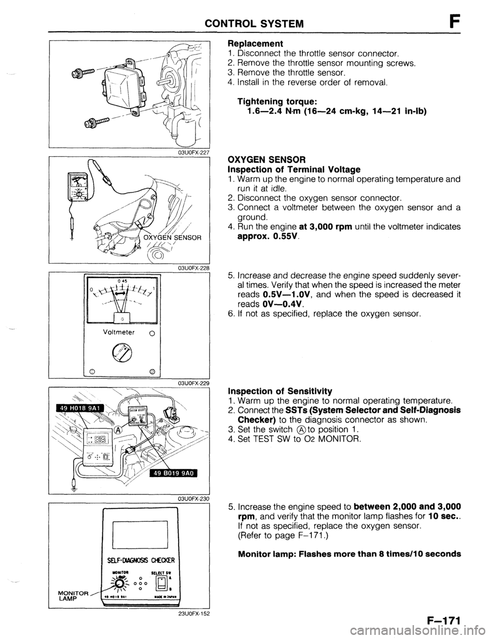
Replacement
1. Disconnect the throttle sensor connector.
2. Remove the throttle sensor mounting screws.
3. Remove the throttle sensor.
4. Install in the reverse order of removal.
Tightening torque:
1.6-2.4 N-m (16-24 cm-kg, 14-21 in-lb)
OXYGEN SENSOR
Inspection of Terminal Voltage
1. Warm up the engine to normal operating temperature and
run it at idle.
2. Disconnect the oxygen sensor connector.
3. Connect a voltmeter between the oxygen sensor and a
ground.
4. Run the engine
at 3,000 rpm until the voltmeter indicates
approx. 0.55V.
5. Increase and decrease the engine speed suddenly sever-
al times. Verify that when the speed is increased the meter
reads
OSV-1 .OV, and when the speed is decreased it
reads
OV-0.4V.
6. If not as specified, replace the oxygen sensor.
Inspection of Sensitivity
1. Warm up the engine to normal operating temperature.
2. Connect the
SSTs (System Selector and Self-Diagnosis
Checker)
to the diagnosis connector as shown.
3. Set the switch @to position 1.
4. Set TEST SW to 02 MONITOR.
5. Increase the engine speed to
between 2,000 and 3,000
rpm,
and verify that the monitor lamp flashes for 10 sec..
If not as specified, replace the oxygen sensor.
(Refer to page F-l 71.)
Monitor lamp: Flashes more than 8 times/l 0 seconds
F-l 71
Page 438 of 1164

F CONTROL SYSTEM
23UOFX-15
23UOFX-15
23UOFX-15
LOCK
4
I
13UOFX-oc
F-l 72
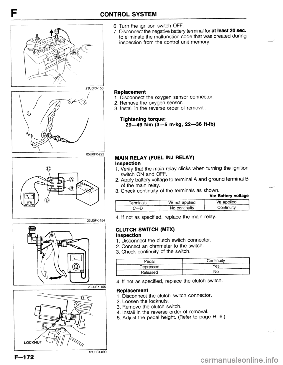
6. Turn the ignition switch OFF.
7. Disconnect the negative battery terminal for
at least 20 sec.
to eliminate the malfunction code that was created during
inspection from the control unit memory.
Replacetnent
1. Disconnect the oxygen sensor connector.
2. Remove the oxygen sensor.
3. Install in the reverse order of removal.
Tightening torque:
29-49 N-m (3-5 m-kg, 22-36 ft-lb)
MAIN RELAY (FUEL INJ RELAY)
Inspection
1. Verify that the main relay clicks when turning the ignition
switch ON and OFF.
2. Apply battery voltage to terminal A and ground terminal E3
of the main relay.
3. Check continuity of the terminals as shown.
VB: Battery voltage
Terminals 1 Ve not applied VB applied
C-D No continuity Continuity
4. If not as specified, replace the main relay.
CLUTCH SWITCH (MTX)
Inspection
1, Disconnect the clutch switch connector.
2. Connect an ohmmeter to the switch.
3. Check continuity of the switch.
Pedal Continuity
Depressed Yes
Released No
4. If not as specified, replace the clutch switch. ,
Replacement
1. Disconnect the clutch switch connector.
2. Loosen the locknuts.
3. Remove the clutch switch.
4. Install in the reverse order of removal.
5. Adjust the pedal height. (Refer to page H-6.)
Page 439 of 1164

CONTROL SYSTEM F
23UOFX-151
WASHER,
REPLACE
9MUOF2-24
05UOFX-25
9MUOF2-24
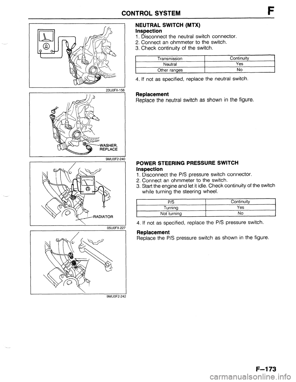
NEUTRAL SWITCH (MTX)
Inspection
1. Disconnect the neutral switch connector.
2. Connect an ohmmeter to the switch.
3. Check continuity of the switch.
Transmission Continuity
Neutral Yes
Other ranges No
4. If not as specified, replace the neutral switch.
Replacement
Replace the neutral switch as shown in the figure.
POWER STEERING PRESSURE SWITCH
Inspection
1. Disconnect the P/S pressure switch connector.
2. Connect an ohmmeter to the switch.
3. Start the engine and let it idle. Check continuity of the switch
while turning the steering wheel.
P/S
Turning
Not turning Continuity
Yes
No
4. If not as specified, replace the P/S pressure switch.
Replacement
Replace the P/S pressure switch as shown in the figure.
F-l 73
Page 440 of 1164
