MAZDA PROTEGE 1992 Workshop Manual
Manufacturer: MAZDA, Model Year: 1992, Model line: PROTEGE, Model: MAZDA PROTEGE 1992Pages: 1164, PDF Size: 81.9 MB
Page 471 of 1164

STARTING SYSTEM G
STARTER INTERLOCK SWITCH (MTX)
CONTACT
IGNITION SWITCH
IG2 ROD
p IG1 ‘NTERlfM$TCH
i BATTERY
I
STARTER
For operator safety, if the clutch pedal is not depressed during starting, battery power will not be supplied
to the starter and the engine will not crank.
Interlock Switch
Inspection
1. Disconnect the interlock switch connector.
2. Connect an ohmmeter to the switch.
3. Check the continuity.
Clutch pedal
----- I_
Depressed
Released 4.
Replace the switch if necessary.
Continuity
--
Yes
No
G-31
Page 472 of 1164

--
-,
Page 473 of 1164

H
CLUTCH
INDEX ......................................................
OUTLINE ..................................................
SPECIFICATIONS .................................... H- 3
TROUBLESHOOTING GUIDE.. .................... H- 3
CLUTCH FLUID ......................................... H- 4
PREPARATION ....................................... H- 4
REPLACEMENT ...................................... H- 4
CLUTCH PEDAL ....................................... H- 5
ADJUSTMENT ........................................ H- 5
REMOVAL / INSPECTION / INSTALLATION.. H- 6
CLUTCH MASTER CYLINDER.. ................... H- 7
PREPARATION ....................................... H- 7
REMOVAL / INSPECTION / INSTALLATION.. H- 7
AIR BLEEDING ....................................... H- 6
OVERHAUL ............................................ H-10
CLUTCH RELEASE CYLINDER ................... H-l 2
PREPARATION ....................................... H-12
REMOVAL / INSTALLATION ...................... H-l 2
AIR BLEEDING (REFER TO PAGE H-8)
OVERHAUL ............................................ H-13
CLUTCH UNIT .......................................... H-14
PREPARATION ....................................... H-14
REMOVAL I INSTALLATION.. .................... H-15
RELEASE BEARING .................................. H-17
INSPECTION .......................................... H-17
CLUTCH COVER ....................................... H-17
INSPECTION .......................................... H-17
CLUTCH DISC .......................................... H-17
INSPECTION .......................................... H-17
PILOT BEARING ....................................... H-16
INSPECTION .......................................... H-16
FLYWHEEL ............................................... H-16
INSPECTION .......................................... H-16
23UOHX-001
Page 474 of 1164

H INDEX
NDEX
CLUTCH SWITCH
SERVICE, SECTION F
23UOHX-00:
2
5. Clutch release fork
Removal / Installation . . . . . . . . . . . . . . . . . . page
H-l 5
6. Clutch cover 1. Clutch pedal
Adjustment . . . . . . . . . . . . . . . . . . . . . . . . . . . . . . . . .
page H- 5
Removal / Inspection /
installation . . . . . . . . . . . . . . . . . . . . . . . . . . . . . . . .
page H- 6
2. Clutch master cylinder
Removal I Inspection I
Installation . . . . . . . . . . . . . . . . . . . . . . . . . . . . . . . .
page H- 7
Air bleeding ,............,..... I ,.,........, page H- 8
Overhaul . . . . . . . . . . . . . . . . . . . . . . . . I ,,.,........
page H-10
3. Clutch release cylinder
Removal / Installation.. . . . . . . . . . . . . . . . . page
H-l 2
Air bleeding . . . . . . . . . . . ..*..................
page H- 8
Overhaul . . . . . . . . . . . . . . . . . . . . . . . . . . . . . . . . . . . . .
page
H-l 3
4. Release bearing
Removal / installation . . . . . . . . . . . . . . . . . . page
H-l 5
Inspection ,.....,..,.,~.,..........,.,,..,,.. page H-l 7
H-2
Removal / Installation .,.......,..,..... page H-l 5
Inspection . . . . . . . . . . . . . . . . . . . . . . . . . . . . . . . . . . .
page H-l 7
7. Clutch disc
Removal I Installation . . . . . . . . . . . . . . . . . . page
H-l 5
Inspection . . . . . . . . . . . . . . . . . . . . . . . . . . . . . . . . . . .
page H-l 7
8. Pilot bearing
Inspection . . . . . . . . . . . . . . . . . . . . . . . . . . . . . . . . . . .
page H-l 8
Removal / Installation.. . . . . . . . . . . . . . . .
page H-l 5
9. Flywheel
Removal I Installation . . . . . . . . . . . . . . . . . . page
H-l 5
Inspection . . . . . . . . . . . . . . . . . . . . . . . . . . . . . . . . . . . page H-18
Page 475 of 1164

OUTLINE, TROUBLESHOOTING GUIDE
OUTLINE
SPECIFICATIONS
-
-
Item
Clutch control Engine/Transaxle B6 SOHC BP SOHC BP DOHC
F!Wl-R GBM-R Hvdraulic
Clutch cover
Clutch disc Type
Set load Diaphragm spring
N
(kg, lb) 1 3,630 (370, 814) 1 3,826 (390, 858) 1 3,846 (392, 862)
30 17.48)
200 (7.87) 215 (8.46) Outer diameter mm (in)
Inner diameter mm (in)
Pressure plate
side mm (in)
Thickness
Flywheel side
mm lit-d
1! , I
130 (5.12) ’ ’
150 i5.91 j
3.5 (0.138) 3.8 (0.150)
3.5 (0.138)
Type Suspended
Clutch pedal
Master cylinder
Release cylinder
Clutch fluid Pedal ratio 6.55
Full stroke mm (in) 135 (5.32)
Height (With carpet)
mm (in) 196-204 (7.72-8.03)
Inner diameter mm (in) 15.87 (0.625)
Inner diameter
mm (in) 19.05 (0.750)
SAE J1703 or FMVSS116 DOT-3
23UOHX-003
TROUBLESHOOTING GUIDE Problem Possible Cause Remedy Page
Slipping
Clutch disc facing worn excessively Replace H-15, 17
Clutch disc facing surface hardened or oil on surface Repair or replace H-15
Pressure plate damaged Repair or replace H-15
Diaphragm spring damaged or weakened Replace H-15
Insufficient clutch pedal play Adjust H- 5
Clutch pedal sticking Repair or replace H- 6
Flywheel damaged Repair or replace H-15, 17 Faulty disen-
Excessive runout or damaged clutch disc Replace H-15, 17 gagement Clutch disc splines rusted or worn Remove rust or replace H-15
Oil on facing Repair or replace H-15
Diaphragm spring weakened Replace H-15
Excessive clutch pedal play Adjust H- 5
Insufficient clutch fluid
Add fluid H- 3
Leakage of clutch fluid Locate and repair or -
replace Clutch vibrates
Oil on facing Repair or replace H-15 when accelerating Torsion rubbers weakened Replace H-15
Clutch disc facing hardened or damaged Repair or replace H-15
Clutch disc facing rivets loose Replace H-15
Pressure plate damaged or excessive runout Replace H-15
Flywheel surface hardened or damaged Repair or replace H-15
Loose or worn engine mount Tighten or replace - Clutch pedal
Pedal shaft not properly lubricated Lubricate or replace H- 6 sticking
Abnormal noise
Clutch release bearing damaged Replace H-15, 17
Poor lubrication of release bearing sleeve Lubricate or replace H-15
Torsion rubbers weakened Replace H-15
Excessive crankshaft end play Repair Refer to Section E
Pilot bearing worn or damaged Replace H-15, 18
Worn pivot points of release fork Repair or replace H-15
^^. .^. I~, ^r
H-3
Page 476 of 1164

H CLUTCH FLUID
CLUTCH FLUID
PREPARATION
SST
49 0259 7708 For
Wrench, flare nut ~ air bleeding
03UOHX-007
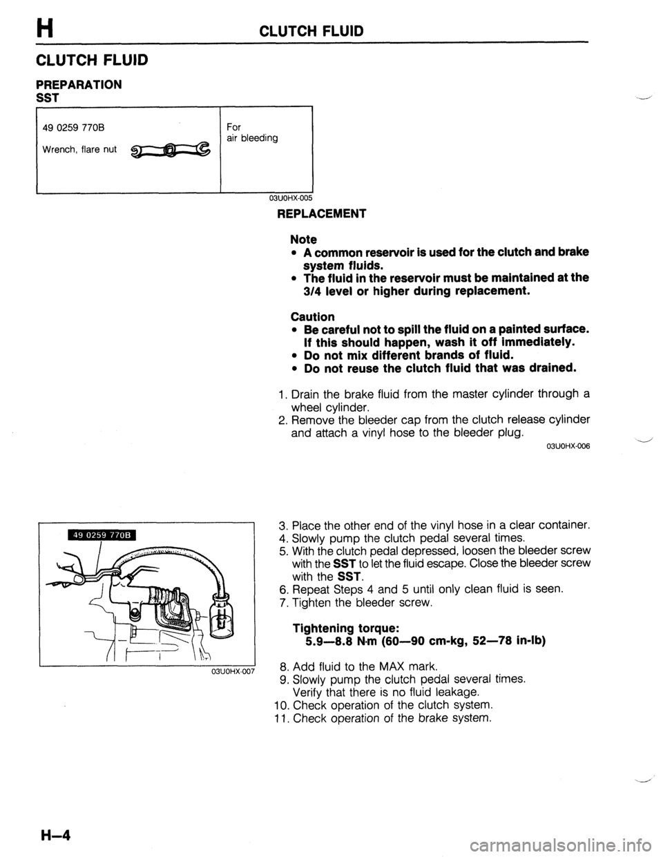
REPLACEMENT
Note
l A common reservoir is used for the clutch and brake
system fluids.
l The fluid in the reservoir must be maintained at the
3/4 level or higher during replacement.
Caution
l Be careful not to spill the fluid on a painted surface.
If this should happen, wash it off Immediately.
l Do not mix different brands of fluid.
l Do not reuse the clutch fluid that was drained.
1. Drain the brake fluid from the master cylinder through a
wheel cylinder.
2. Remove the bleeder cap from the clutch release cylinder
and attach a vinyl hose to the bleeder plug.
03UOHX-006 -
3. Place the other end of the vinyl hose in a clear container.
4. Slowly pump the clutch pedal several times.
5. With the clutch pedal depressed, loosen the bleeder screw
with the
SST to let the fluid escape. Close the bleeder screw
with the
SST.
6. Repeat Steps 4 and 5 until only clean fluid is seen.
7. Tighten the bleeder screw.
Tightening torque:
5.9-8.8 N.m (80-90 cm-kg, 52-78 in-lb)
8. Add fluid to the MAX mark.
9. Slowly pump the clutch pedal several times.
Verify that there is no fluid leakage.
10. Check operation of the clutch system.
11. Check operation of the brake system.
H-4
Page 477 of 1164

CLUTCH PEDAL H
@ 14-19
(1.4-1.9, 10-13)
N.m (m-kg, R-lb)
CLUTCH PEDAL
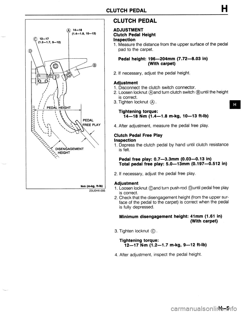
ADJUSTMENT
Clutch Pedal Height
Inspection
1. Measure the distance from the upper surface of the pedal
pad to the carpet.
Pedal height: 196-204mm (7.72-6.03 in)
(With carpet)
2. If necessary, adjust the pedal height.
Adjustment
1. Disconnect the clutch switch connector.
2. Loosen locknut @and turn clutch switch @until the height
is correct.
3. Tighten locknut @ .
Tightening torque:
14-16 N*m (1.4-1.6 m-kg, IO-13 f&lb)
4. After adjustment, measure the pedal free play.
Clutch Pedal Free Play
Inspection
1. Depress the clutch pedal by hand until clutch resistance
is felt.
Pedal free play: 0.7-3.3mm (0.03-0.13 in)
Total pedal free play: 5.0-13mm (0.197-0.512 in)
2. If necessary, adjust the pedal free play.
Adjustment
1. Loosen locknut Oand turn push-rod @until pedal free play
is correct.
2. Check that the disengagement height (from the upper sur-
face of the pedal to the carpet) is correct when the pedal
is fully depressed. 23UOHX-OC
Minimum disengagement height: 41 mm (1.61 in)
(With carpet)
3. Tighten locknut 0.
Tightening torque:
12-17 N-m (1.2-I .7 m-kg, 9-12 ft-lb)
4. After adjustment, inspect the pedal height.
H-5
Page 478 of 1164

H CLUTCH PEDAL
REMOVAL / INSPECTION / INSTALLATION
1. Remove in the order shown in the figure, referring to Removal Note.
2. Inspect all parts and repair or replace as necessary.
Note
l Apply lithium based grease to the bushing and pins before installation.
3. Install in the reverse order of removal, referring to Installation Note.
N.m (m
I (LITHIUM BASED)
l-kg, ft-I
1. Clip
2. Spacer
3. Pin
4. Spacer
5. Nut
6. Push rod
Inspect for damage and bending
7. Clutch fork
8. Nut 9. Washer
10. Bolt
11, Clutch pedal
Adjustment . . . . . . . . . . . . . . . . . . . . . . . . . . . . . . . . . page H-5
12. Spring
13. Spacer
14. Bushing
15. Pedal pad
H-6
Page 479 of 1164

CLUTCH MASTER CYLINDER H
CLUTCH MASTER CYLINDER
PREPARATION
SST
49 0259 770B
Wrench, flare nut For
disconnecting
and connecting
clutch pipe
I I 03UOHX-01
REMOVAL / INSPECTION / INSTALLATION
Caution
l Clutch fluid will damage painted surfaces. Be sure to use a container or rags to collect it. If
fluid gets on a painted surface, wipe it off immediately with a rag.
1. Remove in the order shown in the figure, referring to Removal Note.
2. Inspect all parts and repair or replace as necessary.
3. Install in the reverse order of removal, referring to
Installation Note.
N.m (m-kg, R-lb
23UOHX-007
1. Battery
2. Diagnosis connector
3. Clutch pipe
Removal Note . . . . . . . . . . . . . . . . . . . . . . . . . . . page H- 8
Installation Note . . . . . . . . . . . . . . . . . . . . . . . . . . page H-
8
4. Clip
5. Nut
6. Clutch master cylinder
Check for fluid leakage from the cylinder
bore
Overhaul . . . . . . . ..*........*................ page H-10
Air bleeding . . . . . . . . . . . . . . . . . . . . . . . . . . . . . . . . page H- 8
7. Gasket
H-7
Page 480 of 1164

H CLUTCH MASTER CYLINDER
23UOHX-Ot ,a
\ I 03UOHX-016
7
I
03UOHX-014
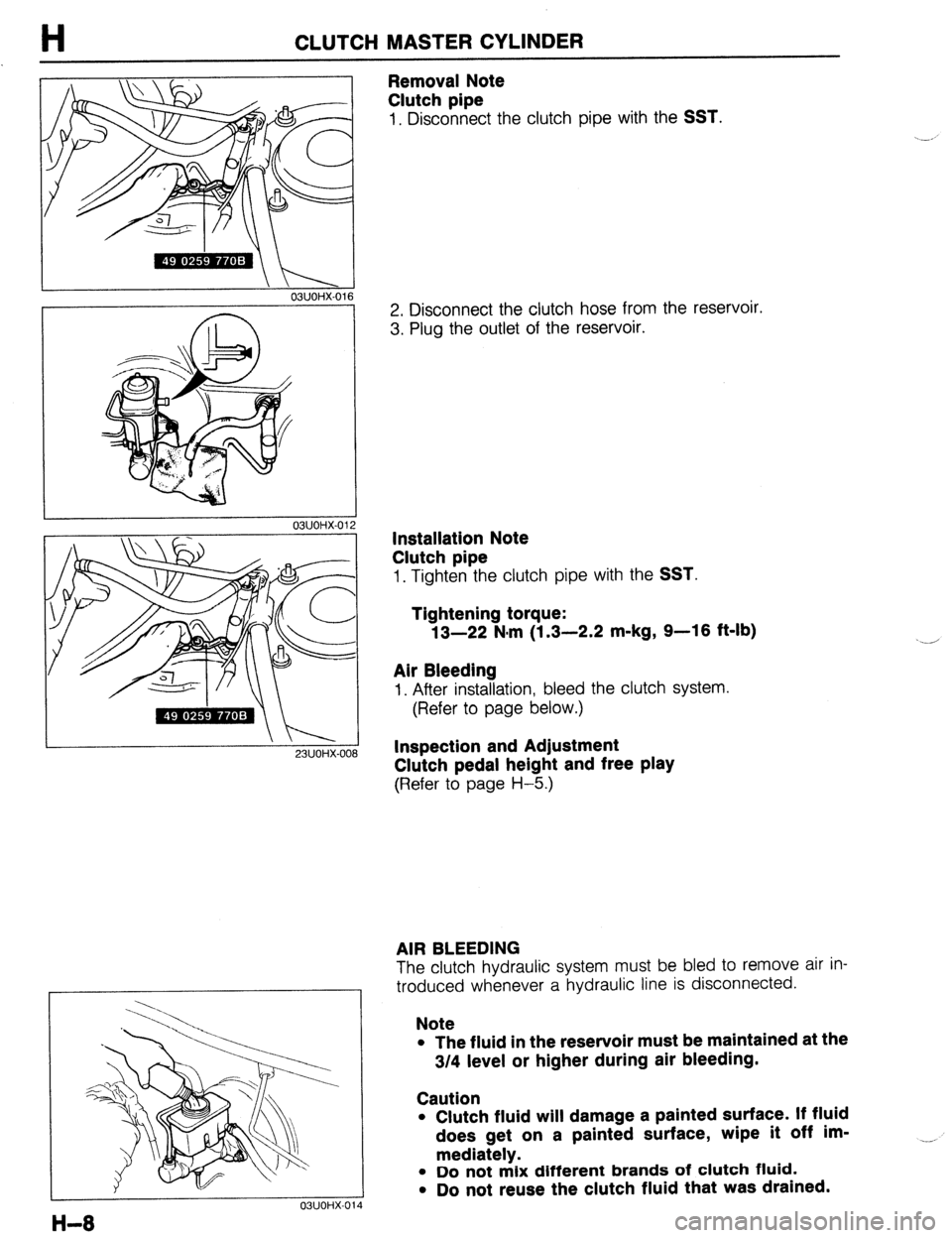
Removal Note
Clutch pipe
1, Disconnect the clutch pipe with the SST.
2. Disconnect the clutch hose from the reservoir.
3. Plug the outlet of the reservoir.
Installation Note
Clutch pipe
1. Tighten the clutch pipe with the SST.
Tightening torque:
13-22 N.m (1.3-2.2 m-kg, 9-16 ft-lb)
Air Bleeding
I. After installation, bleed the clutch system.
(Refer to page below.)
Inspection and Adjustment
Clutch pedal height and free play
(Refer to page H-5.)
AIR BLEEDING
The clutch hydraulic system must be bled to remove air in-
troduced whenever a hydraulic line is disconnected.
Note
l The fluid in the reservoir must be maintained at the
3/4 level or higher during air bleeding.
Caution
l Clutch fluid will damage a painted surface. If fluid
does get on a painted surface, wipe it off im-
mediately.
l Do not mix different brands of clutch fluid.
l Do not reuse the clutch fluid that was drained. __,