MAZDA PROTEGE 1992 Workshop Manual
Manufacturer: MAZDA, Model Year: 1992, Model line: PROTEGE, Model: MAZDA PROTEGE 1992Pages: 1164, PDF Size: 81.9 MB
Page 401 of 1164

PRESSUREREGULATORCONTROLSYSTEM F
03UOFX-17
*
03UOFX-14!
OSUOFX-17
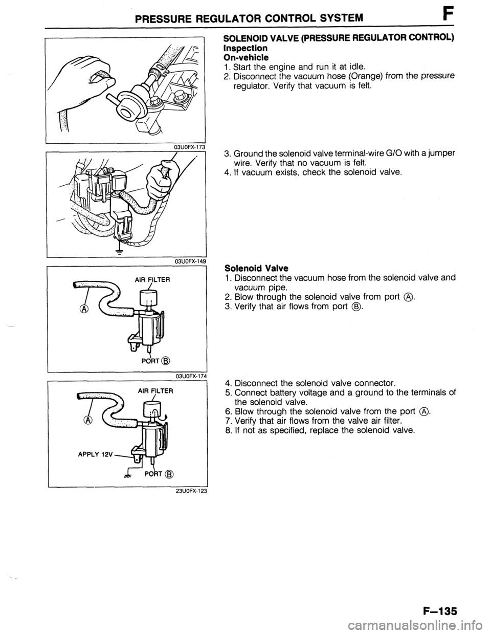
SOLENOID VALVE (PRESSURE REGULATOR CONTROL)
Inspection
On-vehicle
1. Start the engine and run it at idle.
2. Disconnect the vacuum hose (Orange) from the pressure
regulator. Verify that vacuum is felt.
3. Ground the solenoid valve terminal-wire G/O with a jumper
wire. Verify that no vacuum is felt.
4. If vacuum exists, check the solenoid valve.
Solenoid Valve
1. Disconnect the vacuum hose from the solenoid valve and
vacuum pipe.
2. Blow through the solenoid valve from port @
3. Verify that air flows from port @.
4. Disconnect the solenoid valve connector.
5. Connect battery voltage and a ground to the terminals of
the solenoid valve.
6. Blow through the solenoid valve from the port @.
7. Verify that air flows from the valve air filter.
8. If not as specified, replace the solenoid valve.
F-l 35
Page 402 of 1164

F EXHAUST SYSTEM
EXHAUSTSYSTEM
COMPONENT PARTS
Removal / Inspection / Installation
1. Remove in the order shown in the figure.
2. Check the exhaust component parts and repair or replace if necessary.
3. Install in the reverse order of removal.
29149
(3.0-5.0, 22-36) .
^ _ ^.S_
T,
nrrwCE
O-55 (4.1-5.6, 30-41)
N.m (m-kg, ft-lb
23UOFX-1
1, Main silencer
Inspect for deterioration and restriction
2. Pre-silencer
Inspect for deterioration and restriction
3. Catalytic converter
Inspect for deterioration and restriction 4. Front pipe assembly
Inspect for deterioration and restriction
5. Exhaust manifold
Inspect for deterioration and cracks
6. Exhaust manifold insulator
7. Oxygen sensor
Inspection . . . . . . . ..*...................... page F-171 --
‘Y’
F-l 36
Page 403 of 1164

NTROLSYSTEM F
STRUCTURAL VIEW
To reduce CO, HC, and NOx emissions, the following systerns are employed
1. Positive crankcase ventilation (PCV) system
2. Evaporative emission control system
3. Catalytic converter
SEPPRATOR
ECK-AND-CUT
CHARCOAL CANISTER
Page 404 of 1164

F POSITIVE CRANKCASE VENTILATION (PCV) SYSTEM
POSITIVE CRANKCASE VENTILATION (PCV) SYSTEM
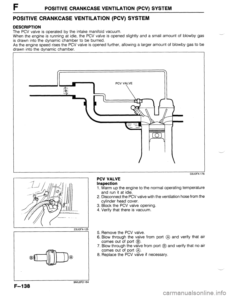
DESCRIPTION
The PCV valve is operated by the intake manifold vacuum.
When the engine is running at idle, the PCV valve is opened slightly and a small amount of blowby gas
is drawn into the dynamic chamber to be burned.
As the engine speed rises the PCV valve is opened further, allowing a larger amount of blowby gas to be
drawn into the dynamic chamber.
23UOFX.1; !5
-7
F-l 38
9MUOF2-164
PCV VALVE
Inspection
OBUOFX-176
1. Warm up the engine to the normal operating temperature
and run it at idle.
2. Disconnect the PCV valve with the ventilation hose from the
cylinder head cover,
3. Block the PCV valve opening.
4. Verify that there is vacuum.
5. Remove the PCV valve.
6. Blow through the valve from port @ and verify that air
comes out of port @I.
7. Blow through the valve from port @ and verify that no air
comes out of port @.
8. Replace the PCV valve if necessary.
Page 405 of 1164

EVAPORATIVE EMISSION CONTROL SYSTEM t
EVAPORATIVE EMISSION CONTROL SYSTEM
DESCRIPTION
/ /
ENGINE ENGINE
CONTROL CONTROL - INPUT - INPUT
UNIT UNIT
- -
SOLENOID VALVE SOLENOID VALVE k k / /
CHECK VALVE CHECK VALVE
(TWO-WAY) (TWO-WAY)
CHARCOAL CHARCOAL
CANISTER CANISTER
CHECK-AND-CUTC CHECK-AND-CUTC
VALVE VALVE
SEPARATOR SEPARATOR TO ENGINE TO ENGINE SIGNALS
The evaporative emission control system consists of the separator, the check-and-cut valve, the two-way
check valve, the charcoal canister, the purge control solenoid valve, the engine control unit (ECU), and the
input devices. The amount of evaporative fumes introduced into the engine and burned is controlled by the
solenoid valve to correspond to the engine’s operating conditions. To maintain best engine performance,
the solenoid valve is controlled by the ECU.
Operation
.._ The solenoid valve (purge control) is controlled by duty signals from the ECU to perform purging of the char-
coal canister. Purging is done when these conditions are met:
(1) After warm-up
(2) Driving in gear
(3) Accelerator pedal depressed (idle switch OFF)
(4) Oxygen sensor functioning normally
F-l 39
Page 406 of 1164

F EVAPORATIVE EMISSION CONTROL SYSTEM
03UOFX-17! 3
03UOFX-180
INSTALLATION DIRECTION
F-l 40
I
23UOFX-126
03UOFX-18
OSUOFX-l&
SYSTEM OPERATION
1 Warm up the engine to normal operating temperature and
run it at idle.
2. Disconnect the vacuum hose from the solenoid valve as
shown in the figure, and verify that no vacuum is felt at the
solenoid valve. -.
3. If not as specified, check the solenoid valve.
SOLENOID VALVE (PURGE CONTROL)
Inspection
1. Disconnect the vacuum hoses from the solenoid valve.
2. Verify that no air flows through the valve.
3. Disconnect the solenoid valve connector and supply bat-
tery voltage as shown in the figure.
4. Verify that air flows through the valve.
5. If not as specified, replace the solenoid valve.
SEPARATOR
Inspection
1. Remove the left side trim.
2. Remove the separator.
3. Visually check the separator for damage. Replace it if
necessary.
CHECK VALVE (TWO-WAY)
Inspection
1. Remove the valve.
2. Check the operation of the valve with a vacuum pump.
Apply approx. 37 mmHg (1.46 inHg)
vacuum at port A Airflow
Apply approx. 44 mmHg (1.73 inHg)
vacuum at port B Airflow
Page 407 of 1164

EVAPORATIVE EMISSION CONTROL SYSTEM F
-l CHECK-AND-CUT VALVE
Inspection
1. Remove the check-and-cut valve.
2. Connect a pressure gauge to the passage connected to
the fuel tank.
3. Blow through the valve from port A and verify that the valve
opens at 6.36-6.34
kPa (0.065-0.065 kg/cm2,
0.92-l 2.09 psi).
4. Remove the pressure gauge and connect it to the passage
to atmosphere.
5. Blow through the valve from port B and verifyjhat the valve
opens at
0.96-4.91 kPa (0.01-0.05 kg/cmL, 0.14-0.71
psi). 1 9MUOF2-194
Note
l The test must be performed with the valve held
horizontally. Otherwise, the ball in the valve will
move out of position and close the passage.
CHARCOAL CANISTER
Inspection
1. Visually check for damage and replace the charcoal canis-
ter if necessary.
F-141
Page 408 of 1164

F DECELERATION CONTROL SYSTEM
DECELERATION CONTROL SYSTEM
DESCRIPTION
The dashpot is used to prevent the throttle valve from suddenly closing
03UOFX-185
1
DASHPOT
Inspection
1. Open the throttle valve fully. Push the dashpot rod with a
finger and verify that it goes into the dashpot slowly.
2. Release the rod and check that it comes out quickly.
3. Replace the dashpot if not as specified.
,,
OBUOFX-18
4. Warm up the engine and run it at idle.
5. Connect a tachometer to the diagnosis connector IG-
terminal and increase engine speed to 4,000 rpm.
6. Slowly decrease the engine speed and check that the le-
ver touches the dashpot rod at the specified speed.
Specification:
l B6 ..**.............,....,.............. Approx. 3,000 rpm
l BP SOHC . ..*..................*.... Approx. 2,700 rpm
l BP DOHC . . . . . . . . . . . . . . . . . . . . ...“... Approx. 3,500 rpm
7. If not as specified, loosen the locknut and turn the dashpot
to adjust.
F-l 42
Page 409 of 1164

FUEL CUT CONTROL SYSTEM F
FUEL CUT CONTROL SYSTEM
DESCRIPTION
This system is used to improve the fuel economy, to prevent engine bucking during deceleration, and to
protect the engine from overspeeding.
23UOFX-127
PREPARATION
SST
r
49 9200 162
03UOFX.191
l7=---T II USE CPNNECTOR A
03UOFX-19
SYSTEM OPERATION
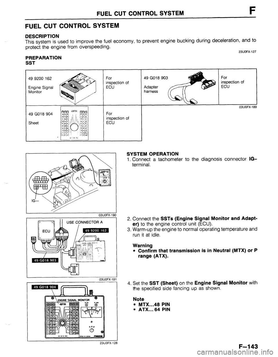
1. Connect a tachometer to the diagnosis connector IG-
terminal.
2. Connect the
SSTs (Engine Signal Monitor and Adapt-
er)
to the engine control unit (ECU).
3. Warm-up the engine to normal operating temperature and
run it at idle.
Warning
l Confirm that transmission is in Neutral (MTX) or P
range (ATX).
4.
Set the SST (Sheet) on the Engine Signal Monitor with
the specified side fancing up as shown.
Note
l MTX...48 PIN
l ATX...64 PIN
I 23UOFX-128
F-l 43
Page 410 of 1164

F FUEL
23UOFX-12:
0-6V
23UOFX- 131
to the terminal 2U or 2V (MTX), 3U or 3V (ATX)
hat the green and red lamps flash alternately.
nd No,3.....ECU terminal 2U (MTX)
3U (ATX)
. . . ..ECU terminal 2V (MTX)
3V (ATX)
6. Increase the engine speed to 4,000 rpm and then suddenly
release the throttle.
7. Verify that the red indicator lamp illuminates while the en-
gine speed is above approx.
1,900 rpm on deceleration.
t aced maximum rpm over 3 sec.
8. Increase the engine speed and verify that the maximum rpm
does not exceed specification.
.
.
. ..“.*..1”*“.-.“.....*......*...
Approx. 7,300 rpm
. . ..I......m....“.....*........m Approx. 6,300 rpm
F-l 44