check oil MAZDA PROTEGE 1992 Repair Manual
[x] Cancel search | Manufacturer: MAZDA, Model Year: 1992, Model line: PROTEGE, Model: MAZDA PROTEGE 1992Pages: 1164, PDF Size: 81.9 MB
Page 719 of 1164

FRONT SUSPENSION (STRUT)
R
03UORX-022
.
.
H 03UOAX-02:
03UORX-02r
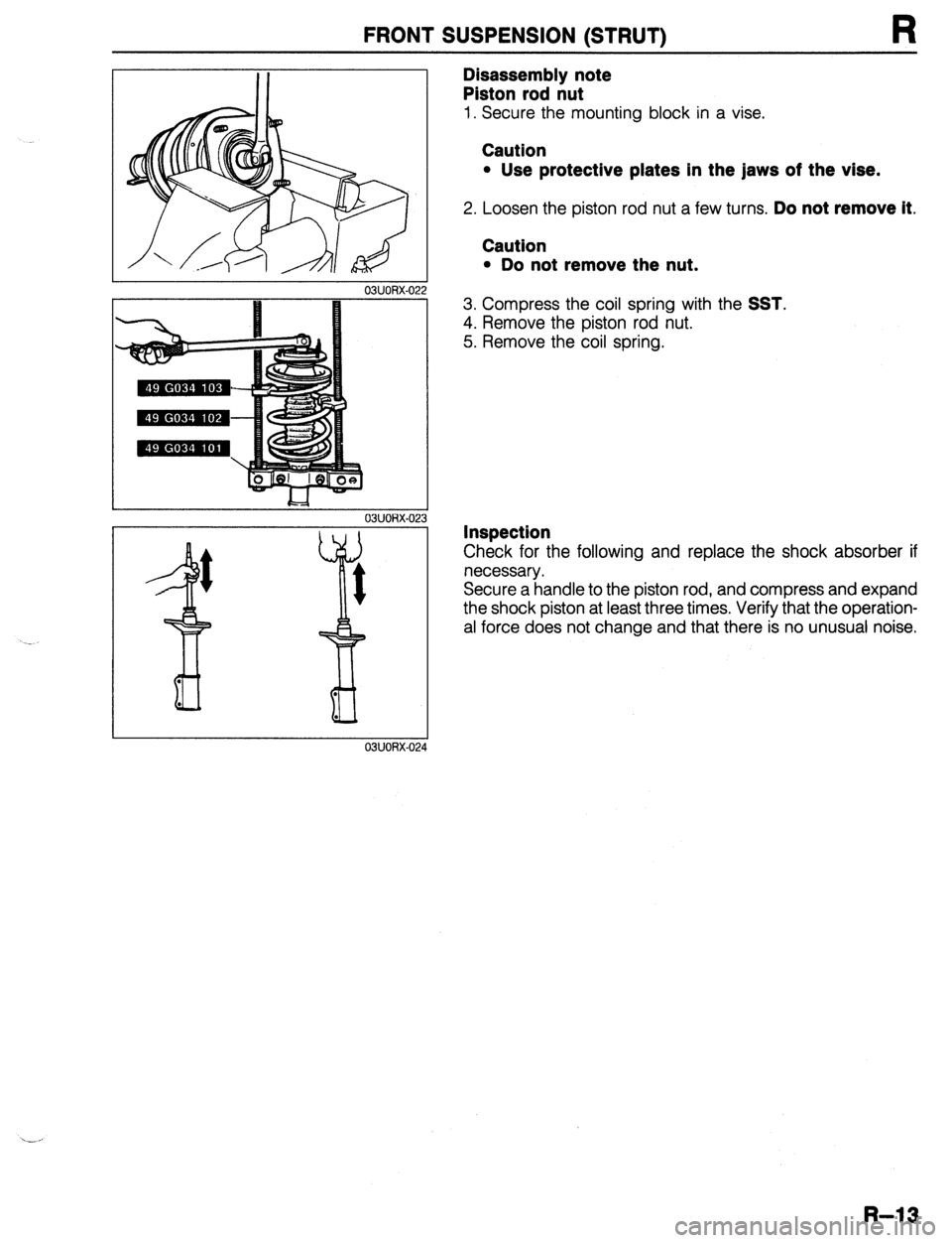
Disassembly note
Piston rod nut
1. Secure the mounting block in a vise.
Caution
l Use protective plates in the jaws of the vise.
2. Loosen the piston rod nut a few turns. Do not remove it.
Caution
l Do not remove the nut.
3. Compress the coil spring with the SST.
4. Remove the piston rod nut.
5. Remove the coil spring.
Inspection
Check for the following and replace the shock absorber if
necessary.
Secure a handle to the piston rod, and compress and expand
the shock piston at least three times. Verify that the operation-
al force does not change and that there is no unusual noise.
R-13
Page 729 of 1164

REAR SUSPENSION (STRUT)
03UORX-04
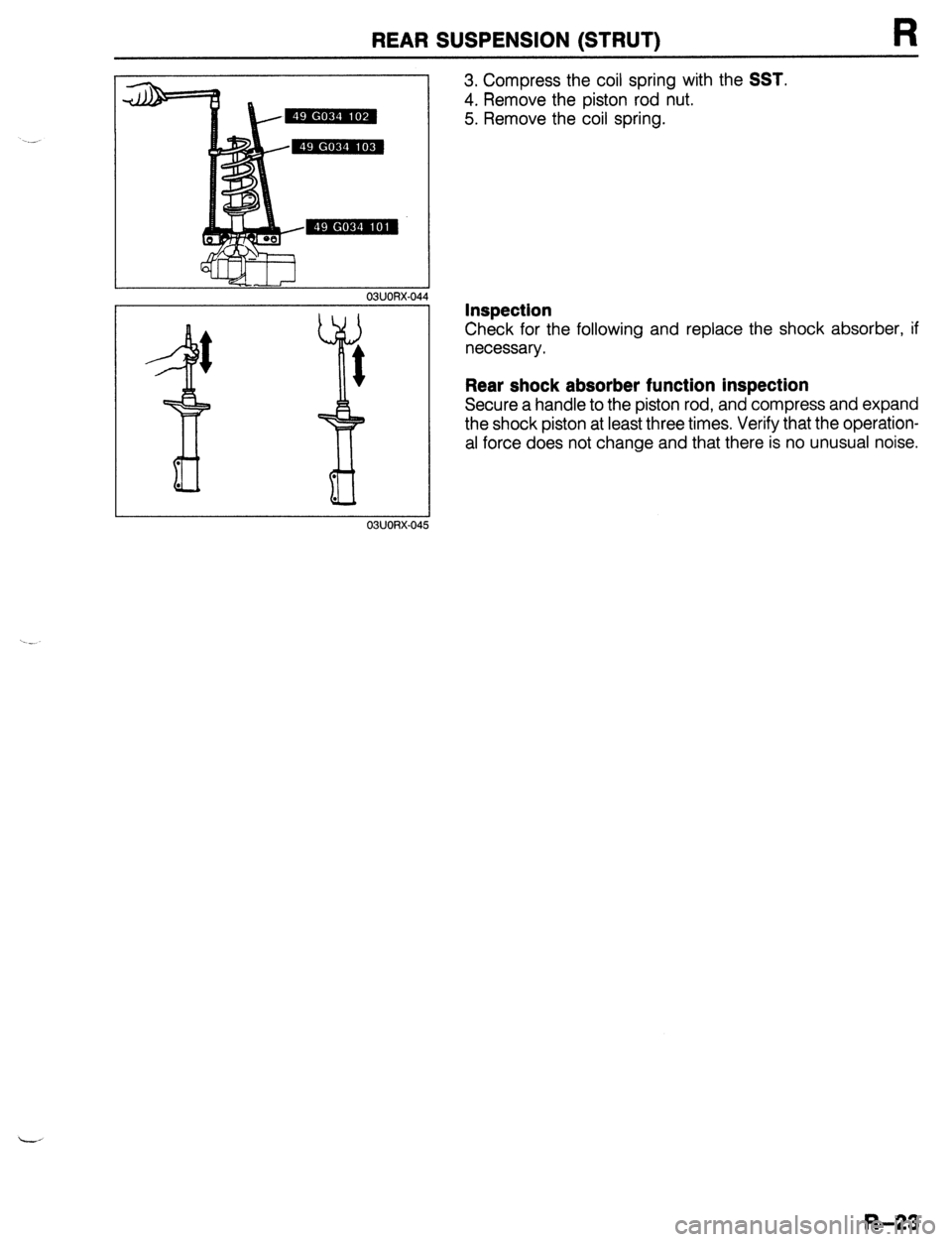
3. Compress the coil spring with the SST.
4. Remove the piston rod nut.
5. Remove the coil spring.
Inspection
Check for the following and replace the shock absorber, if
necessary.
Rear shock absorber function inspection
Secure a handle to the piston rod, and compress and expand
the shock piston at least three times, Verify that the operation-
al force does not change and that there is no unusual noise.
R-23
Page 917 of 1164

WARNING SYSTEM T
13UOTX-07
63U15X-05
, I//
‘nF -
-
-
FUEL
13UOTX.08C
- CHARGE
13UOTX-08
13UOTX-08
Inspection
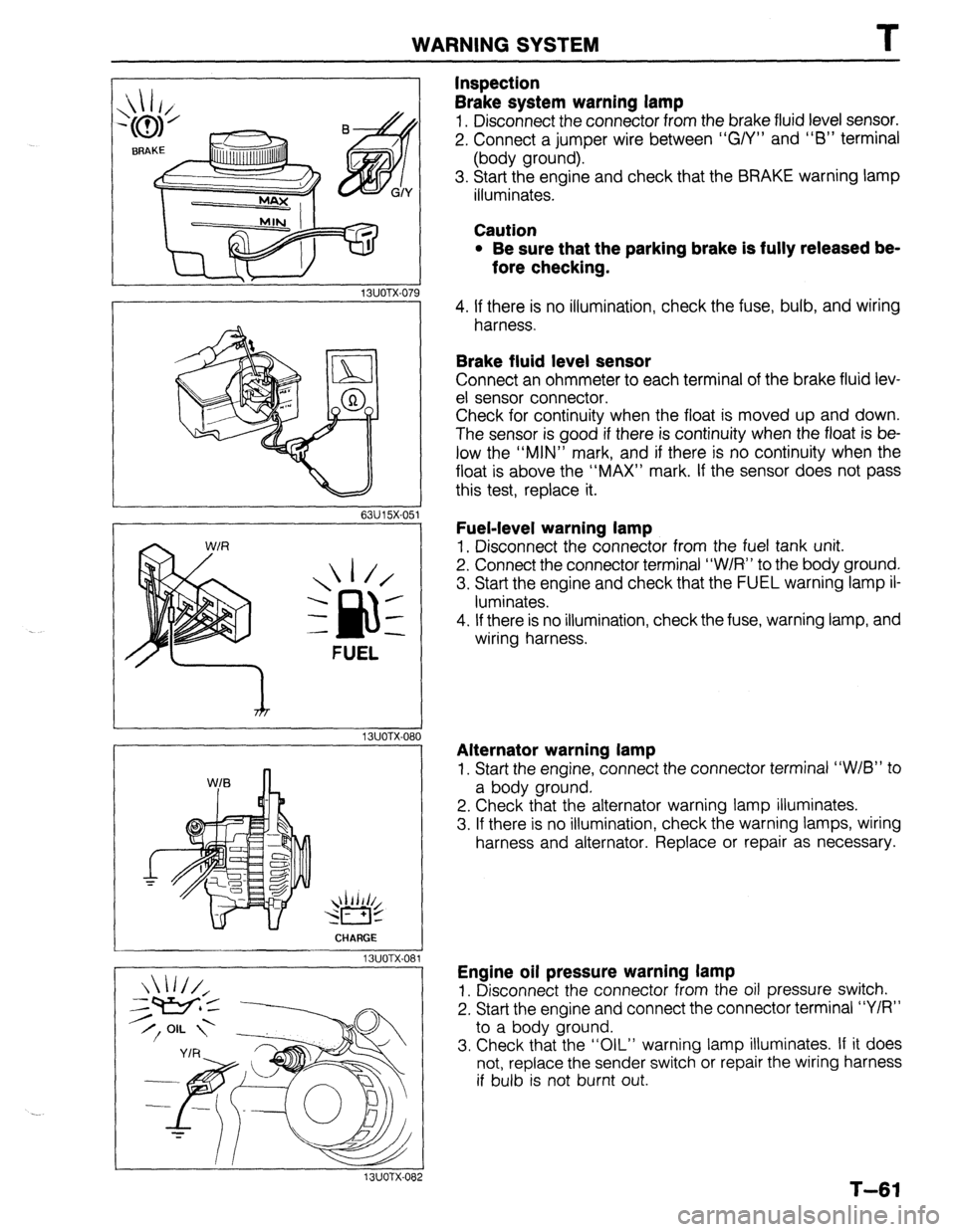
Brake system warning lamp
1. Disconnect the connector from the brake fluid level sensor.
2. Connect a jumper wire between “G/Y” and “6” terminal
(body ground).
3. Start the engine and check that the BRAKE warning lamp
illuminates.
Caution
l Be sure that the parking brake is fully released be-
fore checking.
4. If there is no illumination, check the fuse, bulb, and wiring
harness.
Brake fluid level sensor
Connect an ohmmeter to each terminal of the brake fluid lev-
el sensor connector.
Check for continuity when the float is moved up and down.
The sensor is good if there is continuity when the float is be-
low the “MIN” mark, and if there is no continuity when the
float is above the “MAX” mark. If the sensor does not pass
this test, replace it.
Fuel-level warning lamp
1. Disconnect the connector from the fuel tank unit.
2. Connect the connector terminal “W/R” to the body ground.
3. Start the engine and check that the FUEL warning lamp il-
luminates.
4. If there is no illumination, check the fuse, warning lamp, and
wiring harness.
Alternator warning lamp
1. Start the engine, connect the connector terminal “W/B” to
a body ground.
2. Check that the alternator warning lamp illuminates.
3. If there is no illumination, check the warning lamps, wiring
harness and alternator. Replace or repair as necessary.
Engine oil pressure warning lamp
1. Disconnect the connector from the oil pressure switch.
2. Start the engine and connect the connector terminal “Y/R”
to a body ground.
3. Check that the “OIL” warning lamp illuminates. If it does
not, replace the sender switch or repair the wiring harness
if bulb is not burnt out.
T-61
Page 972 of 1164

U TROUBLESHOOTING GUIDE
Case 1: Insufficient refrigerant
Measured pressure
Low-pressure side: Less than 78.5 kPa (0.8 kg/cm2, 11.4 psi)
High-pressure side: 785-883 kPa (8-9 kg/cm2, 114-128 psi)
Condition
l Outlet air from vents not cold.
l Bubbles seen in sight glass.
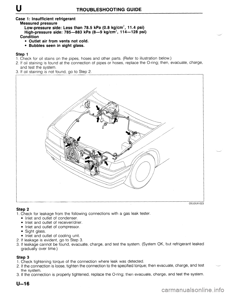
Step 1
1. Check for oil stains on the pipes, hoses and other parts, (Refer to illustration below.)
2. If oil staining is found at the connection of pipes or hoses, replace the O-ring; then, evacuate, charge,
and test the system.
3. If oil staining is not found, go to Step 2.
05UOUX-02
Step 2
1. Check for leakage from the following connections with a gas leak tester.
l Inlet and outlet of condenser.
l Inlet and outlet of receiver/drier.
l Inlet and outlet of compressor.
l Sight glass.
l Inlet and outlet of cooling unit.
2. If leakage is evident, go to Step 3.
3. If leakage cannot be found, evacuate, charge, and test the system. (System OK, but refrigerant leaked
gradually over time.)
Step 3
1. Check tightening torque of the connection where leak was detected.
2. If the connection is loose, tighten the connection to the specified torque; then evacuate, charge, and test
the system. --
3. If the connection is properly tightened, replace the O-ring; then evacuate, charge, and test the system.
U-16
Page 995 of 1164

AIR CONDITIONER U
Dlsassembly / Assembly
Disassemble and assemble as shown in the figure.
1. Evaporator 2. Expansion valve 3. Thermoswitch
Replacement
Expansion valve
Note
l Before replacement of the expansion valve, care-
fully check the refrigeration system, referring to the
troubleshooting information on page U-14.
1. Remove the cooling unit. (Refer to page U-38.)
2. Disassemble the cooling unit. Remove the evaporator and
expansion valve as an assembly.
3. Disconnect the inlet and outlet pipes.
I 4. Remove the capillary tube from the outlet pipe and remove
23UOUX-024 the expansion valve.
5. Install in the reverse order of removal, noting the following.
Note
l Apply clean compressor oil to the O-rings before
connecting the fittings.
Tightening torque
Inlet pipe:
12-15 N-m (1.2-l .5 m-kg, 8.7-l 1 ft-lb)
Outlet pipe:
29-34 Nmrn (3.0-3.5 m-kg, 22-25 ft-lb)
u-39
Page 1000 of 1164

U AIR CONDITIONER
23UOUX-02
Thermal Protector Replacement
1. Removal of discharge valve body
Remove the bolts and carefully remove the discharge valve
body. .-
2. Removal of snap ring and thermal protector
Note
l When removing the thermal protector, do not pull
the harness wires but push the protector out from
its back side.
23UOUX-028 3. Installation of thermal protector
1) Check that the O-ring groove is free from foreign matter.
Apply compressor oil to the O-ring and properly fit it in
the groove.
2) Before installing the thermal protector, check it for con-
tinuity.
23uoux-029 _/”
THERMAL PROTECTOR
23UOUX-03
TH
PR
3) Install the snap ring so that its chamfered edge side faces
the thermal protector (the non-chamfered side faces out-
ward) as shown left.
Make sure the snap ring is seated securely in its groove.
Note
l Install the thermal protector so that its two lead wire
outlet sections are horizontal as shown left.
Page 1001 of 1164

AIR CONDITIONER U
23UOUX-031 DISCHARGE
VALVE BODY
CYLINDER
1
23UOUX-03
4. Installation of discharge valve body
1) Replace the O-ring and gasket with new ones.
Apply compressor oil to the new O-ring and gasket and
properly assemble them.
Note
l Fit the gasket as shown left while checking that its
top side faces upward.
2) Carefully install the discharge valve body on the com-
pressor and finger tighten the six M6 bolts.
Note
Bolt torquing sequence
l Torque the two socket head bolts (A) to the specifi-
cation.
l Torque the four bolts (B) in a diagonal manner to
the specification.
Tightening torgue: 9.8 N,rn (100 cm-kg, 87 in-lb)
u-45
Page 1009 of 1164

AIR CONDITIONER U
CONDENSER
Removal / Installation
1. Discharge the refrigeration system. (Refer to page U-32.)
2. Remove the radiator grille. (Refer to Section S.)
3. Remove the receiver/drier. (Refer to page U-52.)
4. Remove the condenser as shown in the figure.
Note
l Insert a protector such as cardboard between the condenser and the radiator.
l Immediately plug the open fittings to keep moisture out of the system.
5. install the condenser in the reverse order of removal.
Note
l Apply clean compressor oil to the O-rings before connecting the fittings.
l Do not apply compressor oil to the fitting nuts.
l Remove the protector before installing the radiator brackets.
l When installing a new condenser, add compressor oil through the high-pressure pipe port
of the compressor.
Compressor oil: 30 cc (1.83 cu in)
Tightening torque
Condenser inlet: 15-25 N*rn (1.5-2.5 m-kg, 11-18 ft-lb)
Condenser outlet: 9.8-20 N#m (1 .O-2.0 m-kg, 7.2-14 ft-lb)
1. Radiator bracket
2. Radiator 3. Condenser
23UOUX-01
Inspection
Check for the following and repair or replace the condenser
as necessary.;
1. Cracks, damage, or refrigerant leakage.
2. Bent fins.
3. Distorted or damaged condenser inlet or outlet.
u-53
Page 1010 of 1164

AIR CONDITIONER
REFRIGERANT LINES
On-vehicle Inspection
Check for leakage at connections. (Refer to page U-32.)
Repair or replace as necessary.
Replacement
1. Discharge the refrigeration system. (Refer to page U-32.)
2. Replace the faulty pipe or hose.
Note
l Immediately plug the open fittings to keep moisture out of the system.
l Apply clean compressor oil to the O-rings before connecting the fittings.
l Do not apply compressor oil to the fitting nuts.
Tightening torque (fittings):
Location Tightening torque
0 9.8-20 N.m
(1.0-2.0 m-kg, 7.2-14 ft-lb)
0 15-25 N-m (1.5-2.5 m-kg, 11-18 ft-lb)
0 9.8-16 N.m (1.0-1.6 m-kg, 7.2-12 ft-lb)
fa 20-29 N.m
(2.0-3.0 m-ka 15-21 ft-lb)
3. Evacuate, charge, and test the refrigeration system.
1. High-pressure hose
2. Low-pressure hose
3. Cooler pipe No.1 4. Cooler pipe No.2 6. Cooler pipe No.4
5. Cooler
pipe No.3 7. Cooler pipe No.5
u-54
Page 1022 of 1164

TECHNICAL DATA
D. LUBRICATION SYSTEM
Item I I bhricatinn mothnd
Engine
B6 SOHC BP SOHC
Force-fed BP DOHC 1
Requlated pressure kPa (kg/Cm”, p
Inner rotor tooth tip to outer rotor Standard
I-‘---- -.----,
clearance mm (in) Maximum 0.20 (0.0078)
Outer rotor to body clearance mm (in) Standard 0.09-0.18 (0.0035-0.0071)
Maximum 0.22 (0.0087)
Side clearance mm (in) Standard 0.03-0.11 (O.pniq n nnn=’
Maximum n4rl ‘-
“” I r-“.““+..I,
I “. I ‘t (U.0055)
I
1
Oil filter
_ Type
Relief pressure differential
Engine oil
I
Capacity
liters (US qt, Imp qt)
Grade
I Viscosity Full-flow, paper element
kPa (kg/cm’, psi) 1 78-l 18 (0.8-I .2, 1 l-l 7) Tntal /An, nnr*inol 3.4 (3.6, 3.0) 1 4.0 (4.2, 3.5)
3.0 (3.2, 2.6) 1 3.6 (3.8, 3.2)
VII 111Lb1 0.17 (0.18, 0.15)
API Service SG Energy Conserving II (ECQ
1
SA!f InW-Xl 1~ Above -25% (-13OF _ .-.. --
I
I
number
1 Below O’C (32OF) SAE 5W-30
1
E. COOLING SYSTEM
Cooling method EnginelTransaxle
MTX ] ATX 1 MTXl
Water-cooled, forced circulation
J B6 SOHC BP SOHC BP DOHC
, ATX 1 MTX ) ATX
LThermostat
Type Opening temperature
Full-open temperature
Full-open lift
Radiator
_ Type
Cap valve opening pressure
Cooling circuit checking pressure Wax, two-stage
“C (OF) Sub: 83.5-86.5 (182--188), Main: 86.5-89.5 (188-193)
OC (OF) 100 (212)
mm (in) Sub: 1.5 (0.06) min., Main: 8.0 (0.31) min.
Corrugated fin
kPa (kg/cm2, psi) 74-103 (0.75-1.05, 11-15)
kPa (kg/cm’, psi) 103 (1.05, 15)
~..
Cooling fan
Type Electric .-
Number of blades 4
_.---- _I___-
Outer diameter mm (in) 320 (12.6)
--_ ~~-
Capacity w-v 80-12 - 160-12 80-l 2 160-12
6.6 Hi : 13.3
6.6 Hi : 13.3
Current A
Low : 8.8 Low : 8.8
_------ ._____
Water thermoswitch
“c (OF) 1
OFF-ON 97 (207)
I--.
Radiator thermoswitch
__-I____-
OFF+ON “C (OF) 1 1105 (221)( - (105 (221)
TD-8