lock MAZDA PROTEGE 1992 Manual Online
[x] Cancel search | Manufacturer: MAZDA, Model Year: 1992, Model line: PROTEGE, Model: MAZDA PROTEGE 1992Pages: 1164, PDF Size: 81.9 MB
Page 205 of 1164

ASSEMBLY B2
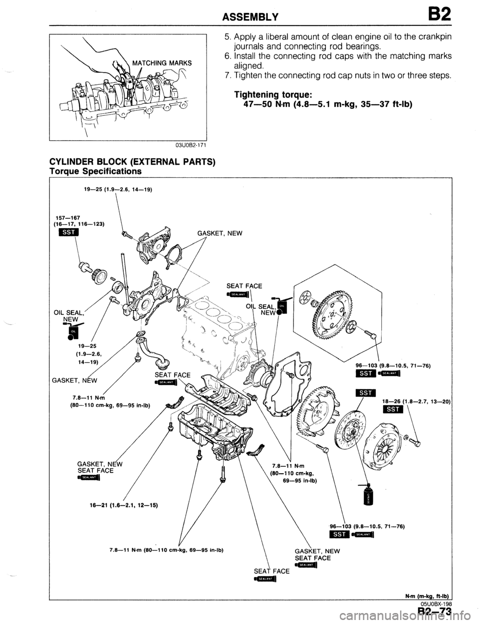
MATCHING MARKS
CYLINDER BLOCK (EXTERNAL PARTS)
Toraue SPecifications 5. Apply a liberal amount of clean engine oil to the crankpin
journals and connecting rod bearings.
6. Install the connecting rod caps with the matching marks
aligned.
7. Tighten the connecting rod cap nuts in two or three steps.
Tightening torque:
47-50 N*m (4.8-5.1 m-kg, 35-37 ft-lb)
19-25 (1.9-2.6, 14-19)
157-l 67
(16-17, 116-1’23)
OIL SEAL.’
/ GASKET. NEW
[SO--110 cm-ka. 69-95 in-lb) 16-26 (1.6-2.7,
13-20
16-21
(1.6-2.1, 12-16)
GASKET, NEW
SEAT FACE
SEAT FACE
N-m (m-kg, ft-lb)
05UOBX-19
B2-7:
Page 209 of 1164

--
ASSEMBLY B2
2311082-06
2311082.04
1
03UO62-09!
J 2311062-063
4. Hold the flywheel with the SST or equivalent.
5. Tighten the bolts in two or three steps in the order shown.
Tightening torque:
96-l 03 N.m (9.6-10.5 m-kg, 71-76 ft-lb)
Clutch Disc and Clutch Cover (MTX)
1. Install the clutch disc and clutch cover using the SST or
equivalent. (Refer to Section H.)
Tightening torque:
16-26 N.m (1.8-2.7 m-kg, 13-20 ft-lb)
Drive Plate (ATX)
1. Remove the sealant from the drive plate holes in the crank-
shaft and from the drive plate lock bolts.
Caution
l If all the previous sealant cannot be removed from
a bolt, replace the bolt.
l Do not apply sealant if a new bolt is used.
2. Set the adapter, drive plate, and backing plate onto the
crankshaft.
3. Apply sealant to the drive plate bolts and install them.
4. Hold the drive plate with the
SST or equivalent.
5. Tighten the bolts in two or three steps in the order shown.
Tightening torque:
96-103 N.m (9.8-10.5 m-kg, 71-76 ft-lb)
Timing Belt Pulley
1, Reverse the direction of the SST or equivalent on the
flywheel.
2311082.064
B2-77
Page 210 of 1164

I32 ASSEMBLY
Qill’ ’ 23UOB2-050
03UOB2-10
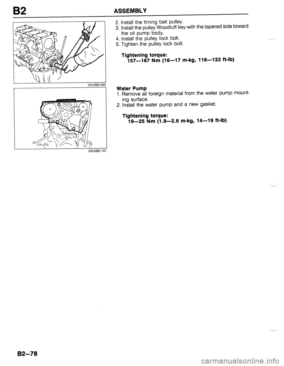
2. Install the timing belt pulley.
3. install the pulley Woodruff key with the tapered side toward
the oil pump body.
4. Install the pulley lock bolt.
5. Tighten the pulley lock bolt.
Tightening torque:
157-167 N#rn (16-17 m-kg, 116-123 ft-lb)
Water Pump
1. Remove all foreign material from the water pump mount-
ing surface.
2. Install the water pump and a new gasket.
Tightening torque:
19-25 N.m (1.9-2.6 m-kg, 14-19 ft-lb)
82-78
Page 212 of 1164

62 ASSEMBLY
I OWOBX-21!
I CYLINDER HEAD SIDE
05UOBX-2
I
05UOBX-21 6
i
17
05UOBX-2
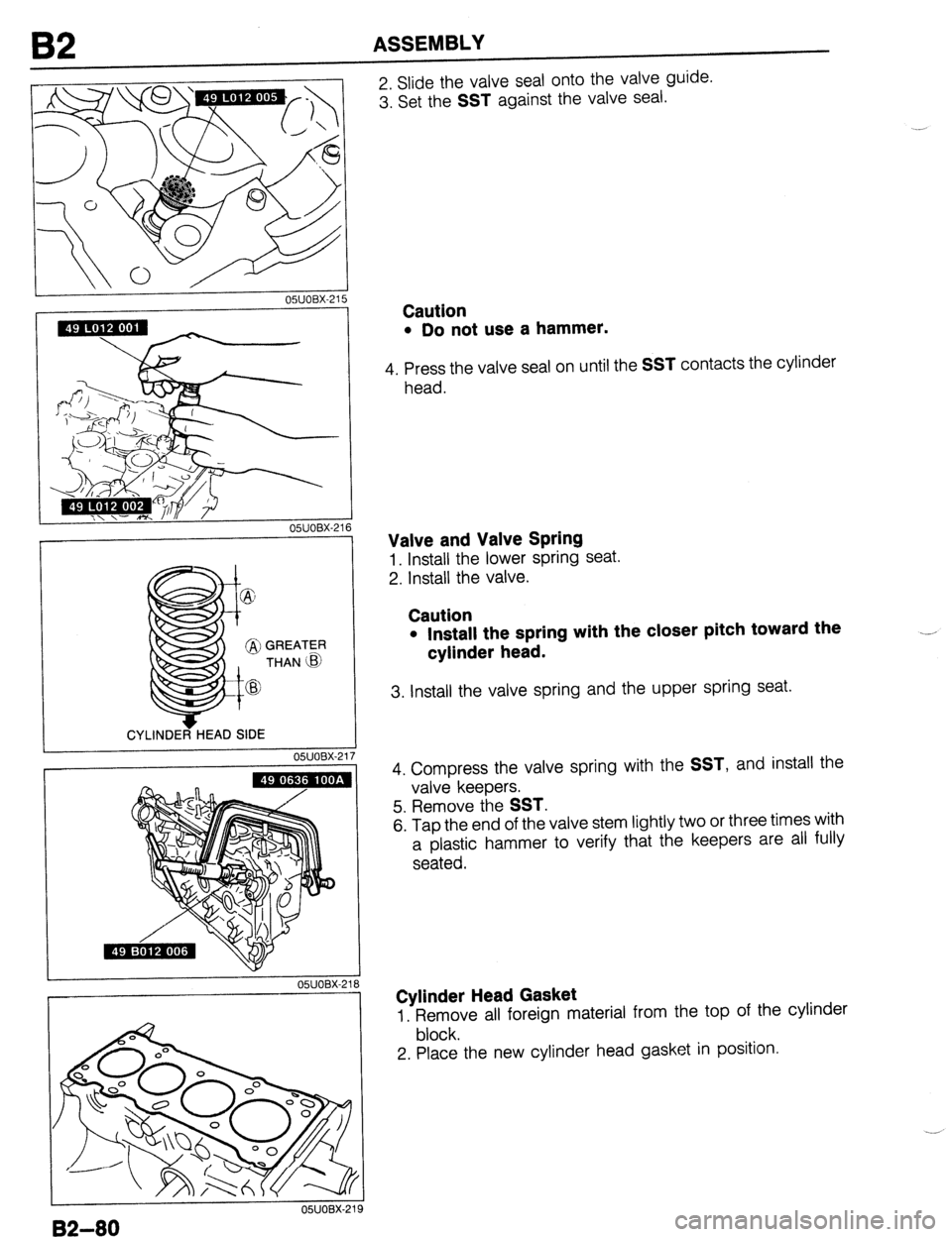
2. Slide the valve seal onto the valve guide.
3. Set the
SST against the valve seal.
Caution
l Do not use a hammer.
4. Press the valve seal on until the SST contacts the cylinder
head.
Valve and Valve Spring
1. Install the lower spring seat.
2. Install the valve.
Caution
l Install the spring with the closer pitch toward the
cylinder head. .---
3. Install the valve spring and the upper spring seat.
4. Compress the valve spring with the
SST, and install the
valve keepers.
5. Remove the
SST.
6. Tap the end of the valve stem lightly two or three times with
a plastic hammer to verify that the keepers are all fully
seated.
Cylinder Head Gasket
1. Remove all foreign material from the top of the cylinder
block.
2. Place the new cylinder head gasket in position.
82-80
Page 215 of 1164

ASSEMBLY 82
DOWEL PIN
23UOB2-042
03UOB2-1 OL Camshaft Pulley
1. Turn the camshafts until the camshaft dowel pins face
straight up.
2. Install the camshaft pulleys with the
I mark (intake side) or
the E mark (exhaust side) straight up.
3. Install the camshaft pulley lock bolts.
4. Hold the camshaft with a wrench at hexagonal portion.
5. Tighten the camshaft pulley lock bolt.
Tightening torque:
49-61 N.m (5.0-6.2 m-kg, 36-45 ft-lb)
Cylinder Head Cover
1. Apply silicone sealant to the shaded areas shown in the
figure.
2. Install the cylinder head cover.
Tightening torque:
4.9-6.6 N.m (50-90 cm-kg, 43-76 in-lb)
82-83
Page 217 of 1164

ASSEMBLY
13EOB2.03
13EOB2-03.
3 1
03UOB2-111
23UOB2-04: 3
Timing Belt
1. Verify that the timing belt pulley mark is aligned with the tim-
ing mark.
2. Verify that the camshaft pulley marks are aligned with the
seal plate marks.
3. Install the timing belt so that there is no looseness at the
idler side or between the camshaft pulleys.
4. Install the pulley boss and pulley lock bolt.
Caution
l Do not turn the crankshaft counterclockwise.
5. Turn the crankshaft two turns clockwise and face the pin
on the pulley boss upright.
6. Verify that the camshaft pulley marks are aligned with the
seal plate marks.
If not aligned, remove the timing belt and repeat from ten-
sioner installation.
7. Turn the crankshaft 1 and 5/6 turns clockwise, and align
the timing belt pulley mark with the tension set mark for prop-
er timing belt tension adjustment.
8. Loosen the tensioner lock bolt to apply tension to the tim-
ing belt.
9. Tighten the tensioner lock bolt.
Tightening torque:
37-52 N-m (3.8-5.3 m-kg, 27-38 ft-lb)
10. Turn the crankshaft 2 and l/6 turns clockwise and verify
that the timing marks are correctly aligned.
B2-85
Page 218 of 1164

I 23UOB2-044
82 ASSEMBLY
DEFLECTION CHECKING POlNT
--; 11. Measure the timing belt deflection by applying moderate
oressure (98 N, 10 kg, 22 lb) midway between the two cam-
shaft pulleys.
If the deflection is not correct, repeat from Step 7 above.
Deflection:
9.0-11.5mm (0.35-0.45 in) at 98 N (10 kg, 22 lb)
Timing Belt Cover
1. Install the lower, middle, and upper covers.
Tightening torque:
7.8-11 N.m (80- ,110 cm-kg, 69-95 in-lb)
I 13EOB2-037
82-86
Pulley lock bolt
1. Hold the flywheel (MIX) or drive plate (ATX) with the SST
and tighten the pulley lock bolt.
Tlghtening torque:
157-167 N.m (16-17 m-kg, 116-123 ft-lb)
Cankshaft pully
1. Install the crankshaft pulley.
2. Install the plate.
3. Tighten the pulley bolts.
Tightening torque:
12-17 N-m (1.25-l -75 m-kg, 9-13 ft-lb)
Water Pump Pulley
1. Install the water pump pulley.
Tightening torque:
7.8-11 N*m (80-110 cm-kg, 69-95 in-lb)
Page 220 of 1164

82 ASSEMBLY
Oil Level Gauge Pipe Stay
1. Install the oil level gauge pipe stay.
Tightening torque:
7.8-l 1 N-m (80-l 10 cm-kg, 89-95 in-lb)
Oil Level Gauge
1. Install the level gauge.
Spark Plug
1, Install the spark plugs.
Tightening torque:
15-23 N*m (1.5-2.3 m-kg, 11-17 ft-lb)
Oil Pressure Switch
1. Install the oil pressure switch.
Tightening torque:
12-18 N-m (120-180 cm-kg, 104-156 in-lb)
Oil Cooler
1. Remove all foreign material from the oil cooler mounting
surface.
2. Apply a small amount of clean engine oil to the rubber seal
of the oil cooler.
3. Install the oil cooler with paint mark (white) facing up.
4. Tighten the oil cooler lock nut.
Tightening torque:
29-39 N.m (3.0-4.0 m-kg, 22-29 ft-lb)
5. Connect the harness to oil pressure switch.
Oil Filter
1. Remove all foreign material from the oil filter mounting
surface.
2. Apply a small amount of clean engine oil to the rubber seal
of the oil filter.
3. Install the oil filter and tighten it by hand until the rubber
seal contacts the base.
4. Tighten the filter 1 and 116 turns with a filter wrench. --_
Page 229 of 1164

INSTALLATION
Step 3
Torque Specifications
16-23 (1.6-2.3, 12-17) 6.9-9.8 N.m (70-100 cm-kg, 61-87 in-lb)
I
m- ,,
// / 31-46 (3.2-4.7, 23-34)
ATX
Y
16-23 (1.6-2.3, 12-17) I 37-52 (3.8-5.3, 27-38) \/r-]z$/ 43-59 (4.4-6.0, 31-43)
COTTER PIN, NEW
/ 31-46 (3.2-4.7. 23-34) 42-67 (4.3-5.8, 31-42)
-_ ..------_ N.m (m-kg, R-lb)
no, Inor, 1.3
L 03UOB2 131
I 0311082-13.
Driveshaft
1. Apply grease to the end of the driveshaft.
Caution
l When installing the driveshaft, be careful not to
damage the oil seal.
l After installation, pull the front hub outward to con-
firm that the driveshaft is securely held by the clip.
2. Install the driveshaft and a new clip.
3. Install the lower arm ball-joint to the knuckle; then tighten
the lock nut.
Tightening torque:
43-59 N-m (4.4-6-O m-kg, 31-43 ft-lb)
4. Install the joint shaft.
5. Tighten the bolts in the order shown.
Tightening torque:
42-62 N-m (4.3-6.3 m-kg, 31-46 ft-lb)
82-97
Page 231 of 1164

INSTALLATION
Step 4
I. Connect the hoses shown in the figure.
Caution Speedometer cable
1. Install the speedometer cable.
Exhaust pipe
1. Install the exhaust pipe and a gasket; then loosely tighten
the lock nuts.
2. Loosely tighten the bracket bolts.
3. Tighten the lock nuts.
Tightening torque:
31-46 N-m (3.2-4.7 m-kg, 23-34 ft-lb)
4. Tighten the bracket bolts.
Tightening torque:
37-52 N.m (3.8-5.3 m-kg, 27-38 ft-lb)
l Position the hose clamp in the original location on the hose, and squeeze the clamp lightly
with large pliers to ensure a good fit.
VACUUM HOSE
(CRUISE CONTROL) BRAKE, VACUUM HOSE 1 VACUUM HOSE
(PURGE CONTROL)
HEATER HOSE
FUE’L HOSE
03UOB2-14
B2-9: