lock MAZDA PROTEGE 1992 Owners Manual
[x] Cancel search | Manufacturer: MAZDA, Model Year: 1992, Model line: PROTEGE, Model: MAZDA PROTEGE 1992Pages: 1164, PDF Size: 81.9 MB
Page 244 of 1164

D OIL PAN
BPSOHCANDDOHC 37-52 (3.8-5.3, 27-38)
I -
16-21 (1.8-2.1, 12-15)
---P 31-46 (3.2-4.7, 23-3’
37-52 (3.8-5.3, 27-36
Ax. GASKET. 1
REPLACE,
cd h 37-52 (3.8-5.3, 27-38) GiSKET,
REPLACE
/ 29-41 (3.0-4.2, 22-30)
-v
44
7.6-l 1 N.m (80-l 10 cm-kg, 69-95 in-lb) N.m (m-kg, ft-It
1 SUODX-0
1. Front exhaust pipe and bracket 3. Oil strainer
2. Oil pan 4. Main bearing support plate (MBSP)
Removal Note . . . . . . . . . . . below Removal Note . . . . . . . . . . . . . . . . . . . . . . . . . . . . page D-l I
. . . . . . . . . . . . . . . . . . . . . . . . . .
Inspect for cracks, deformation and
damage
Installation Note *............,....,......* page D-l 1 Installation Note . . . . . . . . . . . . . . . . . . . . . . . . . . page D-l 1
Removal Note
Oil pan
B6 SOHC
1. Remove the oil pan mounting bolt.
2. Insert a screwdriver or a suitable tool between the MBSP
and oil pan, and pry them.
Caution
l Do not insert the prying tool between the MBSP and
cylinder block.
l Do not damage or scratch the contact surfaces.
3. Remove the oil pan.
D-IO
Page 245 of 1164
OIL PAN
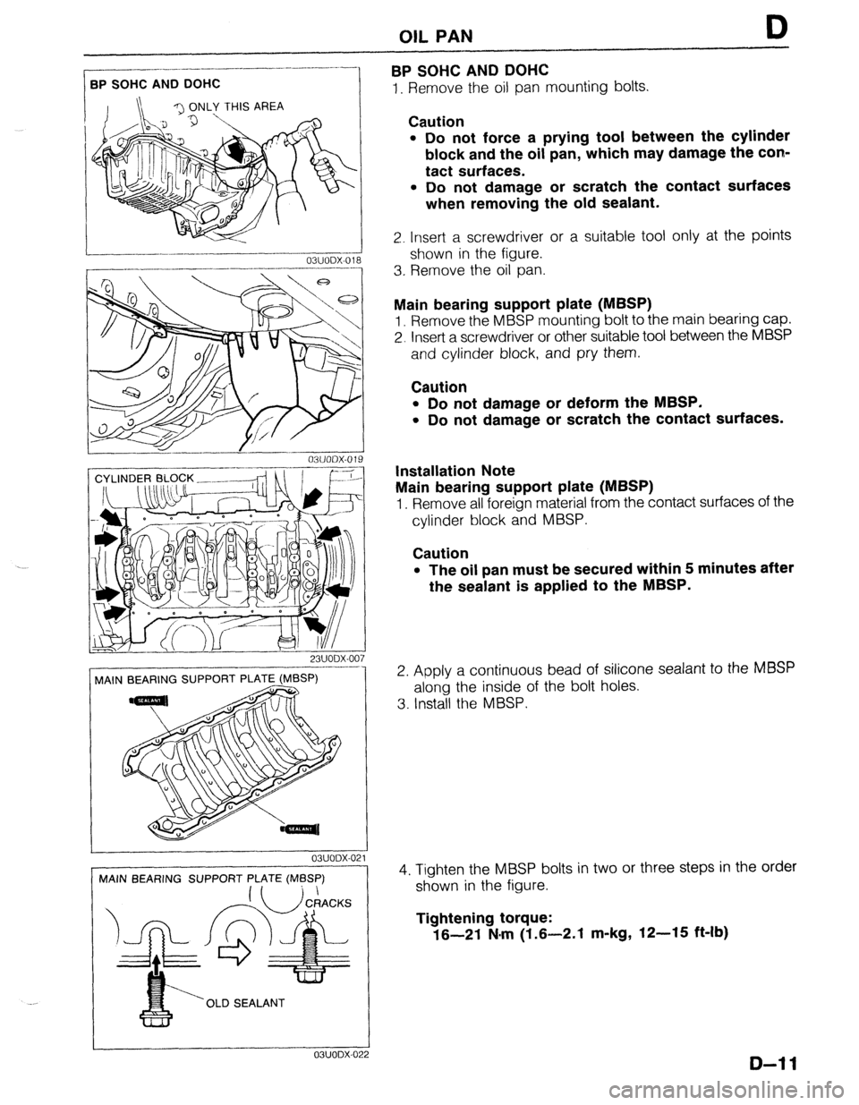
BPSOHCANDDOHC
D
I. Remove the oil pan mounting bolts. .-_-__------- BPSOHCANDDOHC
23UODX-007
MAIN BEARING SUPPORT PLATE (MBSP)
! 03UODX-021
MAIN BEARING SUPPORT PLATE (MBSP)
‘OLD SEALANT ---1_1
OBUODX-0: !2
Caution
l Do not force a prying tool between the cylinder
block and the oil pan, which may damage the con-
tact surfaces.
l Do not damage or scratch the contact surfaces
when removing the old sealant.
2. Insert a screwdriver or a suitable tool only at the points
shown in the figure.
3. Rernove the oil pan.
Main bearing support plate (MBSP)
1. Remove the MBSP mounting bolt to the main bearing cap.
2. Insert a screwdriver or other suitable tool between the MBSP
and cylinder block, and pry them.
Caution
l Do not damage or deform the MBSP.
l Do not damage or scratch the contact surfaces.
Installation Note
Main bearing support plate (MBSP)
1. Remove all foreign material from the contact surfaces of the
cylinder block and MBSP.
Caution
l The oil pan must be secured within 5 minutes after
the sealant is applied to the MBSP.
2. Apply a continuous bead of silicone sealant to the MBSP
along the inside of the bolt holes.
3. Install the MBSP.
4. Tighten the MBSP bolts in two or three steps in the order
shown in the figure.
Tightening torque:
16-21 N.m (1.6-2.1 m-kg, 12-15 ft-lb)
D-l 1
Page 282 of 1164
F OUTLINE
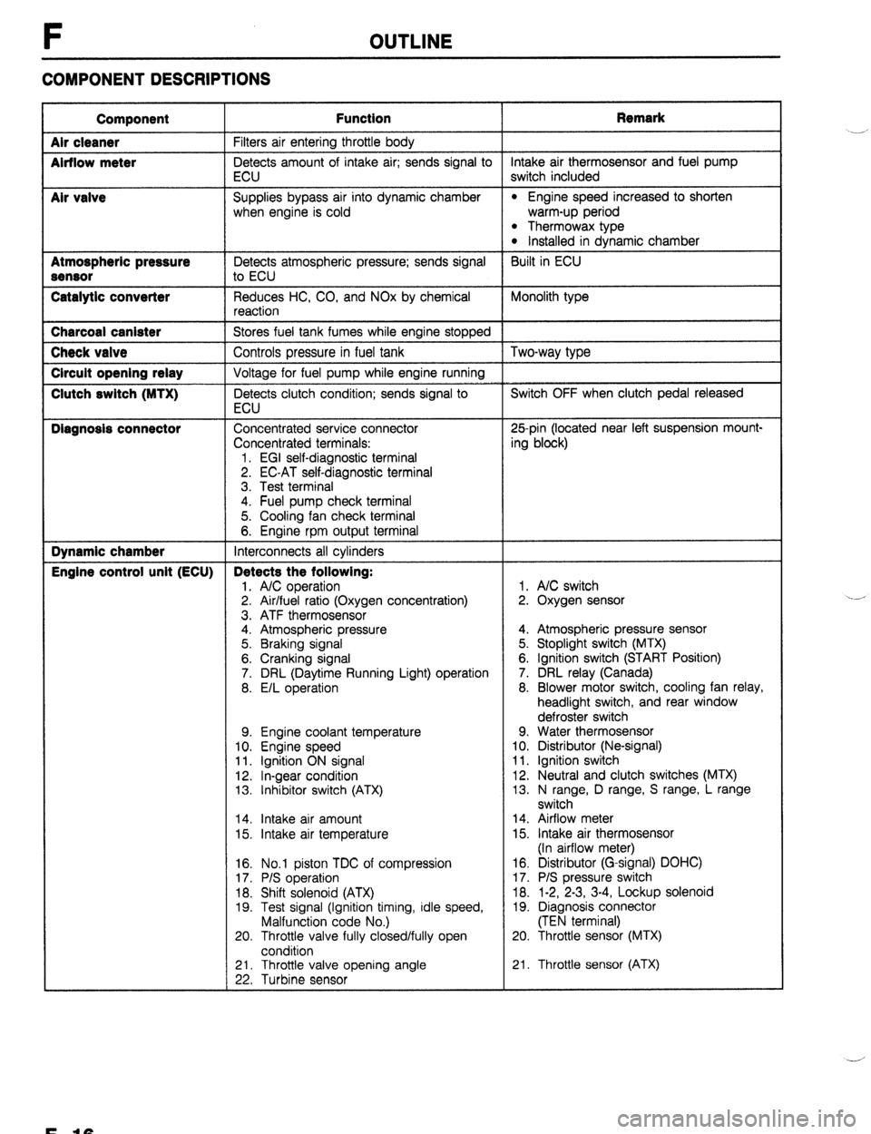
COMPONENT DESCRIPTIONS
Component
Air cleaner
Airflow meter
Mr valve
Atmospheric pressure
Sensor
Catalytic converter Function Remark
Filters air entering throttle body
Detects amount of intake air; sends signal to intake air thermosensor and fuel pump
ECU switch included
Supplies bypass air into dynamic chamber
l Engine speed increased to shorten
when engine is cold warm-up period
l Thermowax type l Installed in dynamic chamber
Detects atmospheric pressure; sends signal Built in ECU
to ECU
Reduces HC, CO, and NOx by chemical Monolith type
reaction Charcoal canister
Stores fuel tank fumes while engine stopped Check valve
Controls pressure in fuel tank Two-way type Circuit opening relay
Voltage for fuel pump while engine running Clutch switch (MTX)
Detects clutch condition; sends signal to Switch OFF when clutch pedal released
ECU Diagnosis connector
Concentrated service connector 25pin (located near left suspension mount-
Concentrated terminals: ing block)
1. EGI self-diagnostic terminal
2. EC-AT self-diagnostic terminal
3. Test terminal
4. Fuel pump check terminal
5. Cooling fan check terminal
6. Engine rpm output terminal Dynamic chamber
Interconnects all cylinders Engine control unit (ECU) Detects the following:
1. A/C operation 1. A/C switch
2. Air/fuel ratio (Oxygen concentration) 2. Oxygen sensor
3. ATF thermosensor
4. Atmospheric pressure 4. Atmospheric pressure sensor
5. Braking signal 5. Stoplight switch (MTX)
6. Cranking signal 6. Ignition switch (START Position)
7. DRL (Daytime Running Light) operation 7. DRL relay (Canada)
8. E/L operation 8. Blower motor switch, cooling fan relay,
headlight switch, and rear window
defroster switch
9. Engine coolant temperature 9. Water thermosensor
10. Engine speed 10. Distributor (Ne-signal)
11. Ignition ON signal 11. Ignition switch
12. In-gear condition 12. Neutral and clutch switches (MTX)
13. Inhibitor switch (ATX) 13. N range, D range, S range, L range
switch
14. Intake air amount 14. Airflow meter
15. Intake air temperature 15. Intake air thermosensor
(In airflow meter)
16. No.1 piston TDC of compression
17. P/S operation
18. Shift solenoid (ATX)
19. Test signal (Ignition timing, idle speed,
Malfunction code No.)
20. Throttle valve fully closed/fully open
condition 16. Distributor (G-signal) DOHC)
17. P/S pressure switch
18. 1-2, 2-3, 3-4, Lockup solenoid
19. Diagnosis connector
(TEN terminal)
20. Throttle sensor (MTX)
21. Throttle valve opening angle
22. Turbine sensor 21. Throttle sensor (ATX) .__r
F-10
Page 300 of 1164

F TROUBLESHOOTING GUIDE
4
CRANKS NORMALLY BUT WILL NOT START (PARTIAL COMBUSTION) - AFTER WARM-UP *Engine cranks at normal speed and shows partial combustion but will not continue to run after running and
DESCRIP- hot soaked
TION *Battery in normal condition
*Engine starts normally when cold
[TROUBLESHOOTING HINTS] 3 Air/Fuel mixture too rich
@ Vapor lock
l Insufficient fuel injection control
*Fuel pressure not held in fuel line after engine stopped
(Correction for coolant temperature)
*High RVP (winter) fuel used in warm weather
l Injector fuel leakage @ Pressure regulator control system malfunction [BP]
switch ON, then check if en
D‘ page F-134
Fuel line pressure:
265-314 kPa (2.7-3.2 kg/cm’, 36-46 psi) ne pressure w
+ If fuel line pressure quickly in-
if fuel return hose is clogged
or
F-=34
Page 306 of 1164
F TROUBLESHOOTING GUIDE
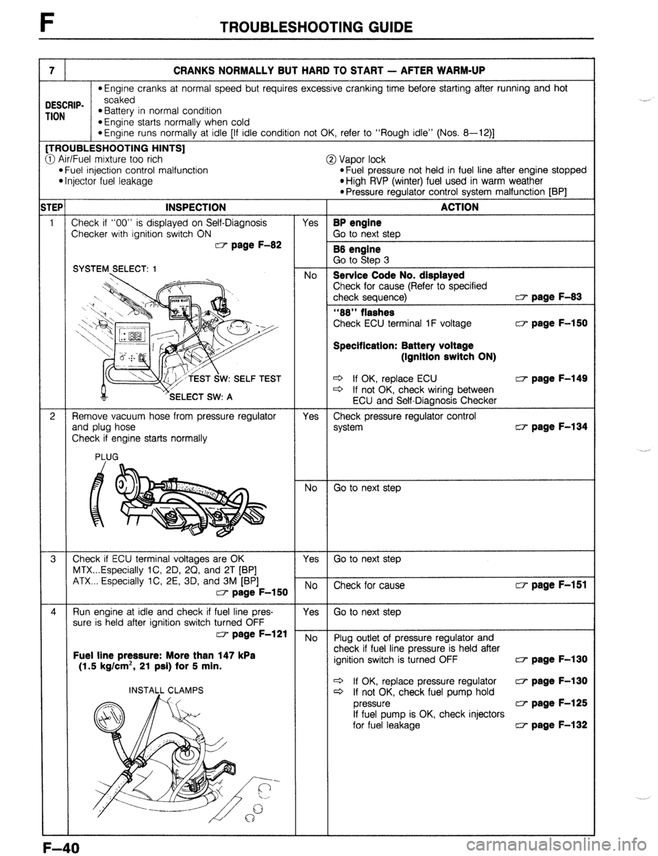
7 CRANKS NORMALLY BUT HARD TO START - AFTER WARM-UP
*Engine cranks at normal speed but requires excessive cranking time before starting after running and hot
DESCRIP- soaked
TION *Battery in normal condition
*Engine starts normally when cold
*Engine runs normally at idle [If idle condition not OK, refer to “Rough idle” (Nos. 8-12)] [TROUBLESHOOTING HINTS]
3 Air/Fuel mixture too rich
@ Vapor lock l Fuel injection control malfunction
*Fuel pressure not held in fuel line after engine stopped l Injector fuel leakage
*High RVP (winter) fuel used in warm weather
l Pressure regulator control system malfunction [BP] w page F-150
Specification: Battery voltage
(Ignition switch ON)
W: SELF TEST c3 If OK, replace ECU w page F-149 * If not OK, check wiring between CT- page F-134
Fuel line pressure: More than 147 kPa
(1.5 kg/cm*, 21 psi) for 5 min. w page F-130
+ If OK, replace pressure regulator CT- page F-130
c3 If not OK, check fuel pump hold w page F-125
If fuel pump is OK, check injectors
for fuel leakage (3 page F-132
F-40
Page 345 of 1164
ENGINE TUNE-UP F
03UOFX.051
03UOFX-051
- w4TEN I
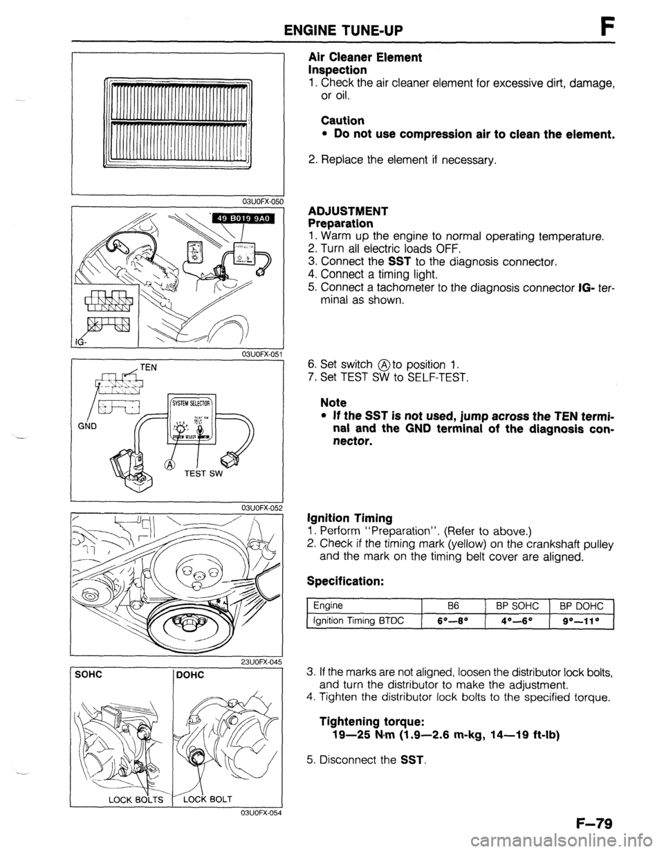
Air Cleaner Element
Inspection
1. Check the air cleaner element for excessive dirt, damage,
or oil.
Caution
l Do not use compression air to clean the element.
2. Replace the element if necessary.
ADJUSTMENT
Preparation
1. Warm up the engine to normal operating temperature.
2. Turn all electric loads OFF.
3. Connect the
SST to the diagnosis connector.
4. Connect a timing light.
5. Connect a tachometer to the diagnosis connector
IG- ter-
minal as shown.
6. Set switch @to position 1.
7. Set TEST SW to SELF-TEST.
Note
l If the SST is not used, jump across the TEN termi-
nal and the GND terminal of the diagnosis con-
nector.
Ignition Timing
1. Perform “Preparation”. (Refer to above.)
2. Check if the timing mark (yellow) on the crankshaft pulley
and the mark on the timing belt cover are aligned.
Specification:
Engine
Ignition Timing BTDC B6 BP SOHC BP DOHC
6O-8* 4O--6O go-110
SOHC DOHC
I 03UOFX-054
3. If the marks are not aligned, loosen the distributor lock bolts,
and turn the distributor to make the adjustment.
4. Tighten the distributor lock bolts to the specified torque.
Tightening torque:
19-25 N#m (1.9-2.6 m-kg, 14-19 ft-lb)
5. Disconnect the SST.
F-79
Page 350 of 1164

F SELF-DIAGNOSIS FUNCTION
Troubleshooting
If a service code number is shown on the SST, check for the cause by using the chart related to the code
number shown.
Service code number
CODE LOCATION OF
NO.
MALFUNCTION OUTPUT SIGNAL PATTERN
SELF-DIAGNOSIS FAIL-SAFE
02
Ne-signal
:E nl-u No Ne-signal
-
03 G-signal
(DOHC) No G-signal Cancels 2-group
injection
06* Vehicle speed
sensor ON
OFF No input signal from Shifting performed
vehicle speed normally
sensor
08 Airflow meter ON
OFF Open or short circuit Basic fuel injection
amount fixed as for two
driving modes
(1) Idle switch ON
(2) Idle switch OFF
09 Water
thermosensor ON
OFF Maintains constant 20%
(68OF) command
10 Intake air
thermosensor Maintains constant 20°C
(68OF) command
12
Throttle sensor
“,E l--uL-l Throttle opening judged
as full stroke lockup not
provided
Atmospheric ON Maintains constant
14 pressure sensor command of sea level
(in ECU)
OFF pressure
15 Oxygen sensor
(inactivation) ON
OFF Sensor output
continues less than
0.55V 95 sec. after
engine starts
(1500 rpm) Cancels engine feedback
operation
Oxygen sensor ON Sensor output Cancels engine feedback
17
(Inversion) continues uncharged operatron
OFF 50 sec. after engine
exceeds 1500 rpm
Solenoid valve ON
25 (pressure
regulator)
OFF u 1 nnluln Open or short crrcurt
“If the marked code numbers appeor, refer to Section K
F-84
Page 351 of 1164

SELF-DIAGNOSIS FUNCTION F
:ODE LOCATION OF
NO.
MALFUNCTION
26 Solenoid valve ON
(purge control)
OFF OUTPUT SIGNAL PATTERN nnnnnll 1 SELF4IAGNOSIS
Open or
short circuit FAIL-SAFE
-
ON
34
ISC valve
OFF u 1 llllJlll r -
41 Solenoid valve ON
(WCS)
[DOHC]
OFF -
Pulse ON No input signal Shifting performed in
55*
i nnnnn
from pulse accordance with signals
generator
OFF generator from vehicle speed
sensor
Open or Solenoid valve(s)
60* 1-2 shift ON
short circuit
solenoid valve
uuuuul performs the shifting with
as little interference as
OFF
possible with driving
performance
2-3 shift ON Lockup not provided
61*
solenoid valve
OFF
UUUI n
3-4 shift ON
62’
solenoid valve
OFF u u u u inn
1.6 sec. 4 sec.
63* Lockup solenoid
valve
u u&m I- Shifting performed
normally
Lockup not provided
0.4 sec.
0.4 sec.
*If the marked code numbers appeor, refer to Section K
Note
l The HOLD indicator does not flash the service code numbers.
l If there is more than one failure present, the code numbers will be indicated in numerical or-
der, lowest number first.
* After repairing a problem, turn the ignition switch OFF and disconnect the negative battery
cable at least 20 seconds to erase the service code numbers from the engine control unit (ECU)
memory.
23UOFX-051
F-85
Page 404 of 1164
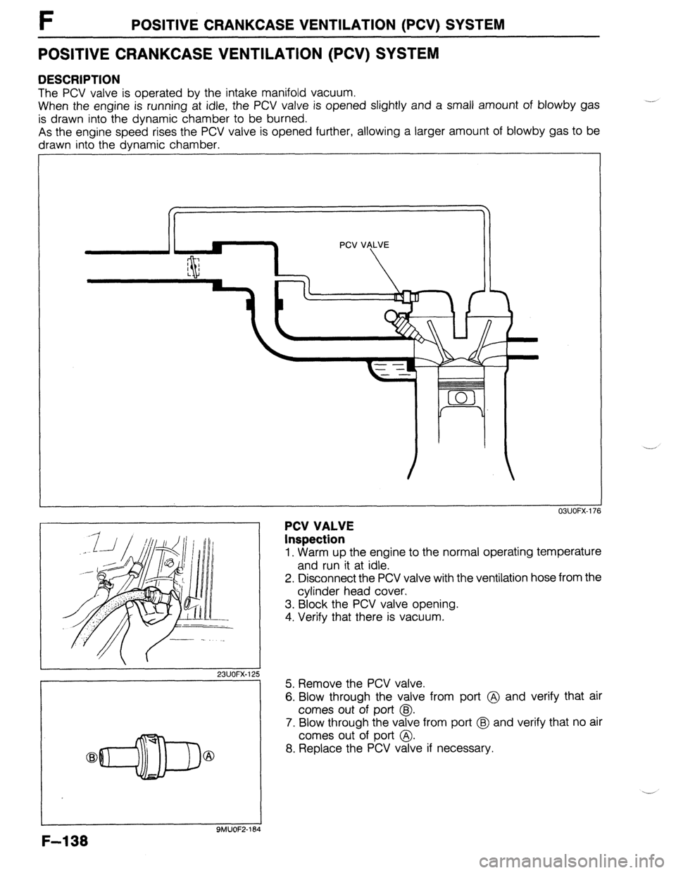
F POSITIVE CRANKCASE VENTILATION (PCV) SYSTEM
POSITIVE CRANKCASE VENTILATION (PCV) SYSTEM
DESCRIPTION
The PCV valve is operated by the intake manifold vacuum.
When the engine is running at idle, the PCV valve is opened slightly and a small amount of blowby gas
is drawn into the dynamic chamber to be burned.
As the engine speed rises the PCV valve is opened further, allowing a larger amount of blowby gas to be
drawn into the dynamic chamber.
23UOFX.1; !5
-7
F-l 38
9MUOF2-164
PCV VALVE
Inspection
OBUOFX-176
1. Warm up the engine to the normal operating temperature
and run it at idle.
2. Disconnect the PCV valve with the ventilation hose from the
cylinder head cover,
3. Block the PCV valve opening.
4. Verify that there is vacuum.
5. Remove the PCV valve.
6. Blow through the valve from port @ and verify that air
comes out of port @I.
7. Blow through the valve from port @ and verify that no air
comes out of port @.
8. Replace the PCV valve if necessary.
Page 408 of 1164

F DECELERATION CONTROL SYSTEM
DECELERATION CONTROL SYSTEM
DESCRIPTION
The dashpot is used to prevent the throttle valve from suddenly closing
03UOFX-185
1
DASHPOT
Inspection
1. Open the throttle valve fully. Push the dashpot rod with a
finger and verify that it goes into the dashpot slowly.
2. Release the rod and check that it comes out quickly.
3. Replace the dashpot if not as specified.
,,
OBUOFX-18
4. Warm up the engine and run it at idle.
5. Connect a tachometer to the diagnosis connector IG-
terminal and increase engine speed to 4,000 rpm.
6. Slowly decrease the engine speed and check that the le-
ver touches the dashpot rod at the specified speed.
Specification:
l B6 ..**.............,....,.............. Approx. 3,000 rpm
l BP SOHC . ..*..................*.... Approx. 2,700 rpm
l BP DOHC . . . . . . . . . . . . . . . . . . . . ...“... Approx. 3,500 rpm
7. If not as specified, loosen the locknut and turn the dashpot
to adjust.
F-l 42