lock MAZDA PROTEGE 1992 Workshop Manual
[x] Cancel search | Manufacturer: MAZDA, Model Year: 1992, Model line: PROTEGE, Model: MAZDA PROTEGE 1992Pages: 1164, PDF Size: 81.9 MB
Page 477 of 1164

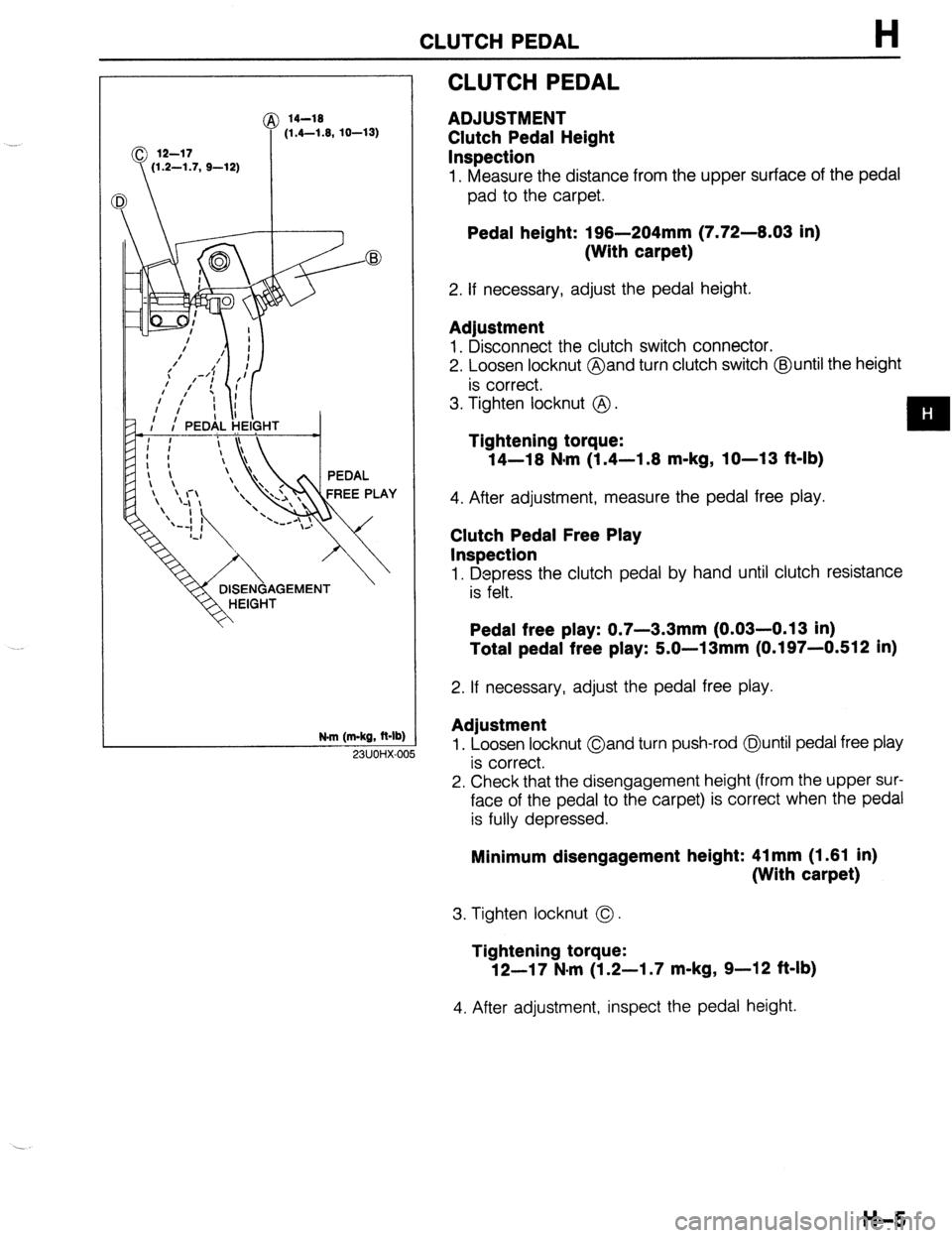
CLUTCH PEDAL H
@ 14-19
(1.4-1.9, 10-13)
N.m (m-kg, R-lb)
CLUTCH PEDAL
ADJUSTMENT
Clutch Pedal Height
Inspection
1. Measure the distance from the upper surface of the pedal
pad to the carpet.
Pedal height: 196-204mm (7.72-6.03 in)
(With carpet)
2. If necessary, adjust the pedal height.
Adjustment
1. Disconnect the clutch switch connector.
2. Loosen locknut @and turn clutch switch @until the height
is correct.
3. Tighten locknut @ .
Tightening torque:
14-16 N*m (1.4-1.6 m-kg, IO-13 f&lb)
4. After adjustment, measure the pedal free play.
Clutch Pedal Free Play
Inspection
1. Depress the clutch pedal by hand until clutch resistance
is felt.
Pedal free play: 0.7-3.3mm (0.03-0.13 in)
Total pedal free play: 5.0-13mm (0.197-0.512 in)
2. If necessary, adjust the pedal free play.
Adjustment
1. Loosen locknut Oand turn push-rod @until pedal free play
is correct.
2. Check that the disengagement height (from the upper sur-
face of the pedal to the carpet) is correct when the pedal
is fully depressed. 23UOHX-OC
Minimum disengagement height: 41 mm (1.61 in)
(With carpet)
3. Tighten locknut 0.
Tightening torque:
12-17 N-m (1.2-I .7 m-kg, 9-12 ft-lb)
4. After adjustment, inspect the pedal height.
H-5
Page 505 of 1164

TRANSAXLE Jl
1, Rear cover
2. Locknut (Primary shaft)
Disassembly Note .,......,,.,......... page Jl-15
3. Stop plate
4. Locknut (Secondary shaft)
Disassembly Note ,..,....,,.,......... page Jl-15
5. 5th shift fork
6. Clutch hub assembly (5th)
Inspection . . . . . . . . . . . . . . . . ..*............... page J l-29
7. Synchronizer ring (5th)
Inspection . . . . . . . . . . . . . . . . . . . . . . . . . . . . . . . . . . page Jl-27
8. 5th gear
Inspection . . . . . . . . . . . . . . . . . . . . . . . . . . . . . . . . . . page Jl-28
9. Gear sleeve
Inspection . . . . . . . . . . . . . . . . ..*...*........... page Jl-28
10. Secondary 5th gear
11. Lock bolt and washer
12. Back-up light switch
13. Neutral switch
14. Transaxle case assembly
15. Magnet
16. Reverse idler shaft
17. Reverse idler gear
Inspection.. . . , . . . . . . . . . . . . . . . , , . , . . . . . . . . . . page J l-27
L ,
03UOJl-022
I
I I
03UOJl-023
18. 5th shift rod
19. 5th shift rod end
20. Pin
21. Crank lever shaft
22. Crank lever assembly
23. Shift fork and shift rod assembly
Disassembly Note ,.................... page Jl-16
24. Steel ball
25. Spring
26. Primary shaft gear assembly
27. Secondary shaft gear assembly
28. Differential assembly
29. Clutch housing
30. Synchronizer spring
31. Clutch hub sleeve
32. Synchronizer key
33. Clutch hub
34. 3rd/4th shift fork
35. Interlock sleeve
36. Control lever
37. lstl2nd shift fork
38. Control rod
39. Control end
03UOJl-021
Preinspection
5th gear thrust clearance
1. Measure the 5th gear thrust clearance with a dial indicator.
Clearance: 0.06-0.26mm (0.0024-0.0102 in)
Maximum : 0.31 mm (0.0122 in)
2. If the clearance exceeds the the maximum, check the con-
tact surfaces of 5th gear and the clutch hub. Replace worn
or damaged parts.
Disassembly note
Locknut
1, Mount the transaxle on the SST.
Jl-15
Page 506 of 1164

Jl TRANSAXLE
SHIFT ROD “I, -
CON-rPOL LEVE$:,
I I 03UOJ2.0
76U07A.22
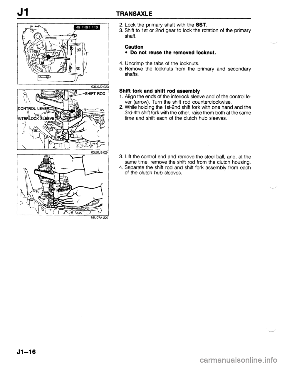
2. Lock the primary shaft with the SST.
3. Shift to 1 st or 2nd gear to lock the rotation of the primary
shaft.
Caution
l Do not reuse the removed locknut.
4. Uncrimp the tabs of the locknuts.
5. Remove the locknuts from the primary and secondary
shafts.
Shift fork and shift rod assembly
1. Align the ends of the interlock sleeve and of the control le-
ver (arrow). Turn the shift rod counterclockwise.
2. While holding the 1 st-2nd shift fork with one hand and the
3rd-4th shift fork with the other, raise them both at the same
time and shift each of the clutch hub sleeves.
3. Lift the control end and remove the steel ball, and, at the
same time, remove the shift rod from the clutch housing.
4. Separate the shift rod and shift fork assembly from each
of the clutch hub sleeves.
51-16
Page 535 of 1164

TRANSAXLE Jl
1. Control rod
2. Control end
3. lstl2nd shift fork
4. Control lever
5. Interlock sleeve
6.3rd/4th shift fork
7. Clutch hub
8. Synchronizer key
9. Clutch hub sleeve
10. Synchronizer spring
11. Clutch housing
12. Differential assembly
13. Secondary shaft gear assembly
Assembly Note . . . . . . . . . . . . . . . . . . . . . . . . . . page Jl-45
14. Primary shaft gear assembly
Assembly Note.. . . . . . . . . . . . . . . . . . . . . . . , . page J 1-45
15. Spring
16. Steel ball
17. Shift fork and shift rod assembly
Assembly Note.. . . . . . . . . . . , . . . . . . . . . , . . , page J 1-45
18. Crank lever assembly
Assembly Note. . . . . . . . . . . . . . . . . . . . . . . . . . page Jl-46
19. Crank lever shaft
Assembly Note.. . . . . . . . . . . , , . . . . . . . . . . . . page Jl -46
20. Pin
21. 5th shift rod end
Assembly Note . . . . . . . . . . . . . . . . . . . . . . . . . . page 31-46
22. 5th shift rod
Assembly Note.. . . . . . . . . . . . . . . . . . . . . . . . . page J 1-46
23. Reverse idler gear
Assembly Note . . . . . . . . . . . . . . . . . . . . . . . . . . page Jl-46
24. Reverse idler shaft
Assembly Note... . . . . . . . . . . . . . . . . . . . . . . . page Jl -46
25 Magnet
26. Transaxle case assembly
Assembly Note.. . . . . . . . . . . . . . . . . . . . . . . . . page Jl -47
27. Neutral switch
28. Back-up light switch
29. Lock bolt and washer
30. Secondary 5th gear
31. Gear sleeve
32. 5th gear
33. Synchronizer ring (5th)
34. Clutch hub assembly (5th)
Assembly Note.. . . . . . . . . . . . . . . . . . . . . . . . . page Jl-47
35. 5th shift fork
Assembly Note . . . . . . . . . . . . . . . . . . . . . . . . . . page Jl-47
36. Stop plate
37. Locknut (Secondary shaft)
Assembly Note.. . . . . . . . . . . . . . . . . . . . . . . . . page Jl-47
38. Locknut (Primary shaft)
Assembly Note.. . . . . . . . . . . . . . . . . . . . . . . . . page J 1-47
39. Rear cover
13UOJl-005
Assembly note
Primary shaft gear assembly and secondary shaft gear
assembly
1. Install the primary shaft gear assembly and the secondary
shaft gear assembly together.
03UOJl-115 Shift fork and shift rod assembly
1. Shift to 2nd gear and position the shift fork and shift rod
assembly as shown.
03UOJ2-088
51-45
Page 536 of 1164

Jl TRANSAXLE
I I 03UOJ2-089
03UOJ2-091 3
03UOJ2-09
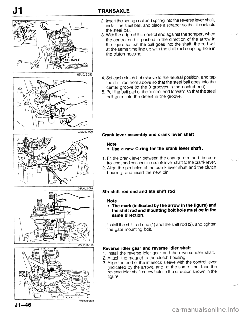
2. Insert the spring seat and spring into the reverse lever shaft,
install the steel ball, and place a scraper so that it contacts
the steel ball.
3. With the edge of the control end against the scraper, when
the control end is pushed in the direction of the arrow in
the figure so that the ball goes into the shaft, the rod will
at the same time line up with the shift rod coupling hole in
the clutch housing.
4. Set each clutch hub sleeve to the neutral position, and tap
the shift rod from above so that the steel ball goes into the
center groove (of the 3 grooves in the control end).
5. Pull the ball part of the control end forward so that the steel
ball goes into the detent in the groove.
Crank lever assembly and crank lever shaft
Note
l Use a new O-ring for the crank lever shaft.
1. Fit the crank lever between the change arm and the con-
trol end, and connect the crank lever shaft to the crank lever.
2. Align the pin holes of the crank lever shaft and the clutch
housing, and insert the new pin. -’
5th shift rod end and 5th shift rod
Note
l The mark (indicated by the arrow in the figure) and
the shift rod end mounting bolt hole must be in the
same direction.
1. Install the shift rod end (1) and the shift rod (2), and tighten
the gate mounting bolt.
Reverse idler gear and reverse idler shaft
1. Install the reverse idler gear and the reverse idler shaft.
2. Attach the magnet to the clutch housing.
3. Align the end of the interlock sleeve with the control lever
(indicated by the arrow), and, at the same time, face the
reverse idler shaft screw hole in the direction shown in the
figure.
Jl-46
Page 537 of 1164

TRANSAXLE Jl
- 23UOJl-01
03UOJl-11
03UOJl-14
I 03UOJl-11
Transaxle case assembly
1, Apply a thin coat of sealant to the contact surfaces of the
clutch housing and transaxle case, tighten the transaxle case
installation bolts to the specified torque.
Tightening torque:
19-26 Nom (1.9-2.6 m-kg, 14-19 ft-lb)
Clutch hub assembly (6th) and 6th shlft fork
1. Install the clutch hub assembly (5th) and the 5th shift fork
together.
Locknut
1. Shift to 1 st gear.
2. Lock the primary shaft with the
SST.
3. Tighten new locknuts on the primary and secondary shafts.
Tightening torque:
126-206 N*m (13.0-21 m-kg, 94-152 ft-lb)
4. Stake the locknuts.
5. Measure the 5th gear thrust clearance with a dial indicator.
Clearance: 0.06-0.26mm (0.0024-0.0102 in)
Maximum : 0.31 mm (0.0122 in)
6. If not as specified, reassemble the transaxle.
Jl-47
Page 540 of 1164

03UOJi-12 3
03UOJl-124
L 03UOJl.126 I-
03UOJl-12
Jl TRANSAXLE
Driveshaft
Caution
l Verify that the oil seal is not damaged.
l Do not damage the oil seal
1. Insert the clip with the end-gap at the top of the groove.
2. Apply transaxle oil around the oil seal lip. Install the
driveshaft.
3. Verify that the driveshaft is correctly seated by pulling on
the shaft.
4. Connect the lower arm to the knuckle and tighten the clinch
bolt.
Tightening torque:
43-59 N-m (4.4-6.0 m-kg, 32-43 ft-lb)
Stabilizer (BP SOHC)
1. Tighten the nut until the specified amount of thread is ex-
posed at the end of the bolt.
Dimension A: 17-l 9mm (0.67-0.75 in)
Tie-rod end
1. Install the locknut.
Tightening torque:
42-57 N-m (4.3-5.6 m-kg, 31-42 ft-lb)
2. Secure the locknut with a new cotter pin.
Engine mounting member
1. Install the bolts and nuts as shown.
Tightening torque
@ : 37-52 N,m (3.6-5.3 m-kg, 27-36 ft-lb)
@I: 64-89 N-m (6.5-9.1 m-kg, 47-66 ft-lb)
51-50
Page 543 of 1164

DIFFERENTIAL Jl
DISASSEMBLY / INSPECTION / ASSEMBLY
Caution
l Do not remove the inner race if not necessary.
1. Before disassembly, inspect the backlash of side gear and pinion gear, referring to Preinspection.
2. Disassemble in the order shown in the figure, referring to Disassembly Note.
3. Inspect all parts and repair or replace as necessary.
4. Assemble in the reverse order of disassembly, referring to
Assembly Note.
5. Measure the backlash after assembly, referring to Backlash of Side Gear and Pinion Gear.
1. Roll pin 7. Side bearing inner race
13UOJl-00:
Assembly Note .......................... page Jl -55 Disassembly Note.. ..................
2. Pinion shaft Inspection .................................
3. Thrust washer Assembly Note .........................
4. Pinion gear 8. Speedometer drive gear
Inspect for wear and cracks Assembly Note.. .......................
Preinspection ............................ page J l-53 9. Side bearing inner race
Inspection of backlash.. ............ page Jl-55 Disassembly Note.. ..................
5. Side gear Inspection .................................
Inspect for wear and cracks Assembly Note.. .......................
Preinspection ............................ page J l-53 10. Ring gear and ring case
Inspection of backlash.. ............ page Jl-55 Inspection .................................
6. Thrust washer
03UOJl-13 4
page Jl-54
page Jl -54
page Jl-55
page Jl -55
page Jl-54
page Jl-54
page Jl-55
page Jl-54
Preinspection
Backlash of side gear and pinion gear
Measure the backlash by the following procedure.
1. Install the left and right driveshafts in the differential as-
sem bly.
2. Support the driveshafts on V-blocks as shown in the figure.
3. Measure the backlash of both pinion gears.
Backlash: O-O. 1 mm (O-0.004 in)
51-53
Page 545 of 1164

DIFFERENTIAL Jl
03UOJl-138
Assembly Note
Speedometer drive gear
1. Install the speedometer drive gear as shown in the figure.
1
03UOJl-13!
I
03UOJ2-10
I
03UOJl-14
I 03UOJl-14 .l
Side bearing inner race (Side opposite ring gear)
1. Install the speedometer drive gear.
2. Install the new side bearing inner race with the
SST.
Side bearing inner race (Ring gear side)
1. Install the new bearing inner race with the SST.
Roll pin
1, Install the new roll pin as shown in the figure to hold the
pinion shaft.
Backlash of Side Gear and Pinion Gear
Measure the backlash by the following procedure.
1. Install the driveshafts in the differential assembly.
2. Support the driveshafts on V-blocks as shown in the figure.
3. Measure the backlash of both pinion gears.
Backlash: O-O.1 mm (O-0.004 in)
4. If not as specified, select the proper thrust washers.
(Refer to preinspection, page Jl-53.)
Jl-55
Page 561 of 1164

TRANSAXLE J2
Sth/Reverse Gear and Housing Parts
1. Disassemble in the order shown in the figure, referring to Disassembly Note.
1. Rear cover
2. Locknut (Primary shaft)
Disassembly Note . . . . . . . . . . . . . . . . . . . . . page J2-14
3. Locknut (Secondary shaft)
Disassembly Note . . . . . . . . . . . . . . . . . . . . .
page J2-14
4. Primary reverse synchronizer gear
Inspection . . . . . . . . . . . . . . . . . . . . . . . . . . . . . . . . . . page J2-22
5. Synchronizer ring (Reverse)
Inspection . . . . . . . . . . . . . . . . . . . . . . . . . . . . . . . . . . page J2-22
6. Secondary reverse synchronizer gear
Inspection ,,.*.....,.,..............I.,..,.. page J2-22
7. Roll pin
8. 5th/Reverse shift fork
9. Clutch hub assembly (5thIReverse) 14. Lock bolt
15. Guide bolt
16. Lock bolt, ball, and spring
17. Transaxle case assembly
18. Magnet
19. Reverse idler shaft
20. Reverse idler gear
21. Lock bolt
22. 5thlReverse shift rod and clip
23. 5th/Reverse shift rod end
24. Pin
25. Crank lever shaft
26. Crank lever assembly
27. Shift fork and shift rod assembly
.- . .
Inspection . . . . . . . . . . . . . . . . . . . . . . . . . . . . . . . . . .
page J2-22 Disassembly Note . . . . . . . . . . . . . . . . . . . . . page
JZ-14
10. Synchronizer ring (5th) 28. Steel ball
Inspection . . . . . . . . . . . . . . . . . . . . . . . . . . . . . . . . . . page J2-22 29. Spring
11. 5th gear 30. Primary shaft gear assembly
Inspection . . . . . . . . . . . . . . . . . . . . . . . . . . . . . . . . . . page J2-22 31. Secondary shaft gear assembly
12. Gear sleeve 32. Differential assembly
13. Secondary 5th gear 33. Clutch housing
Inspection . . . . . . . . . . . . . . . . . . . . . . . . . . . . . . . . . . page J2-22
52-l 3