MERCEDES-BENZ C-CLASS COUPE 2015 Owners Manual
Manufacturer: MERCEDES-BENZ, Model Year: 2015, Model line: C-CLASS COUPE, Model: MERCEDES-BENZ C-CLASS COUPE 2015Pages: 385, PDF Size: 13.12 MB
Page 211 of 385
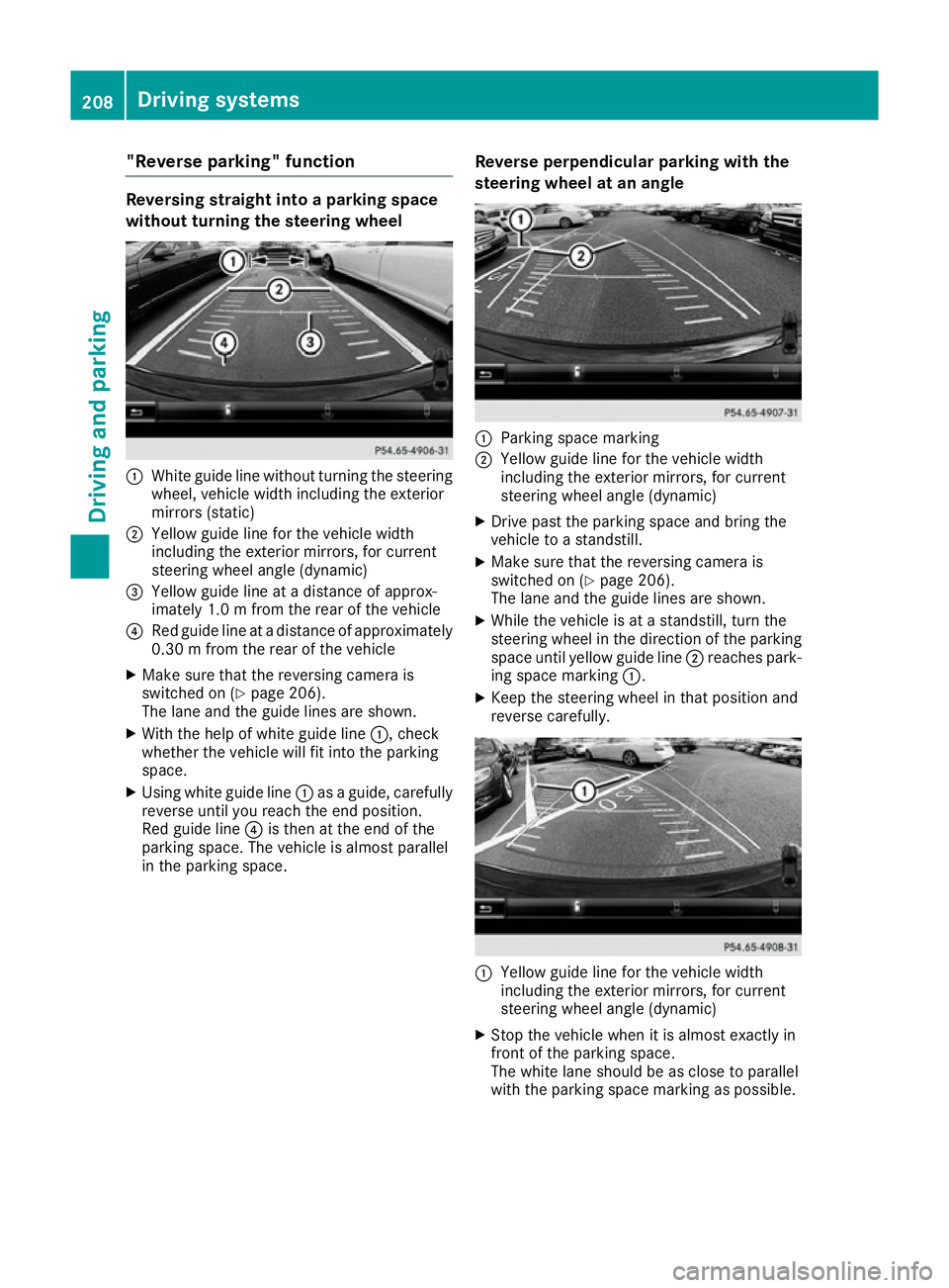
"Reverse parking" function
Reversing straight into
aparking space
without turning the steering wheel :
White guide line without turning the steering
wheel, vehicle width including the exterior
mirrors (static)
; Yellowg uide line for the vehicle width
including the exterior mirrors, for current
steering wheel angle (dynamic)
= Yellowg uide line at adistance of approx-
imately 1.0 mfrom the rear of the vehicle
? Red guide line at adistance of approximately
0.30 mfrom the rear of the vehicle
X Make sure that the reversing camera is
switched on (Y page 206).
The lane and the guide lines are shown.
X With the help of white guide line :,check
whether the vehicle will fit into the parking
space.
X Using white guide line :asag uide,c arefully
reverse until you reach the end position.
Red guide line ?is then at the end of the
parking space. The vehicle is almost parallel
in the parking space. Reverse perpendicular parking with the
steering wheel at an angle :
Parking space marking
; Yellowg uide line for the vehicle width
including the exterior mirrors, for current
steering wheel angle (dynamic)
X Drive past the parking space and bring the
vehicle to astandstill.
X Make sure that the reversing camera is
switched on (Y page 206).
The lane and the guide lines are shown.
X While the vehicle is at astandstill, turn the
steering wheel in the direction of the parking space until yellow guide line ;reaches park-
ing space marking :.
X Keep the steering wheel in that position and
reverse carefully. :
Yellowg uide line for the vehicle width
including the exterior mirrors, for current
steering wheel angle (dynamic)
X Stop the vehicle when it is almost exactly in
front of the parking space.
The white lane should be as close to parallel
with the parking space marking as possible. 208
Driving systemsDriving and parking
Page 212 of 385
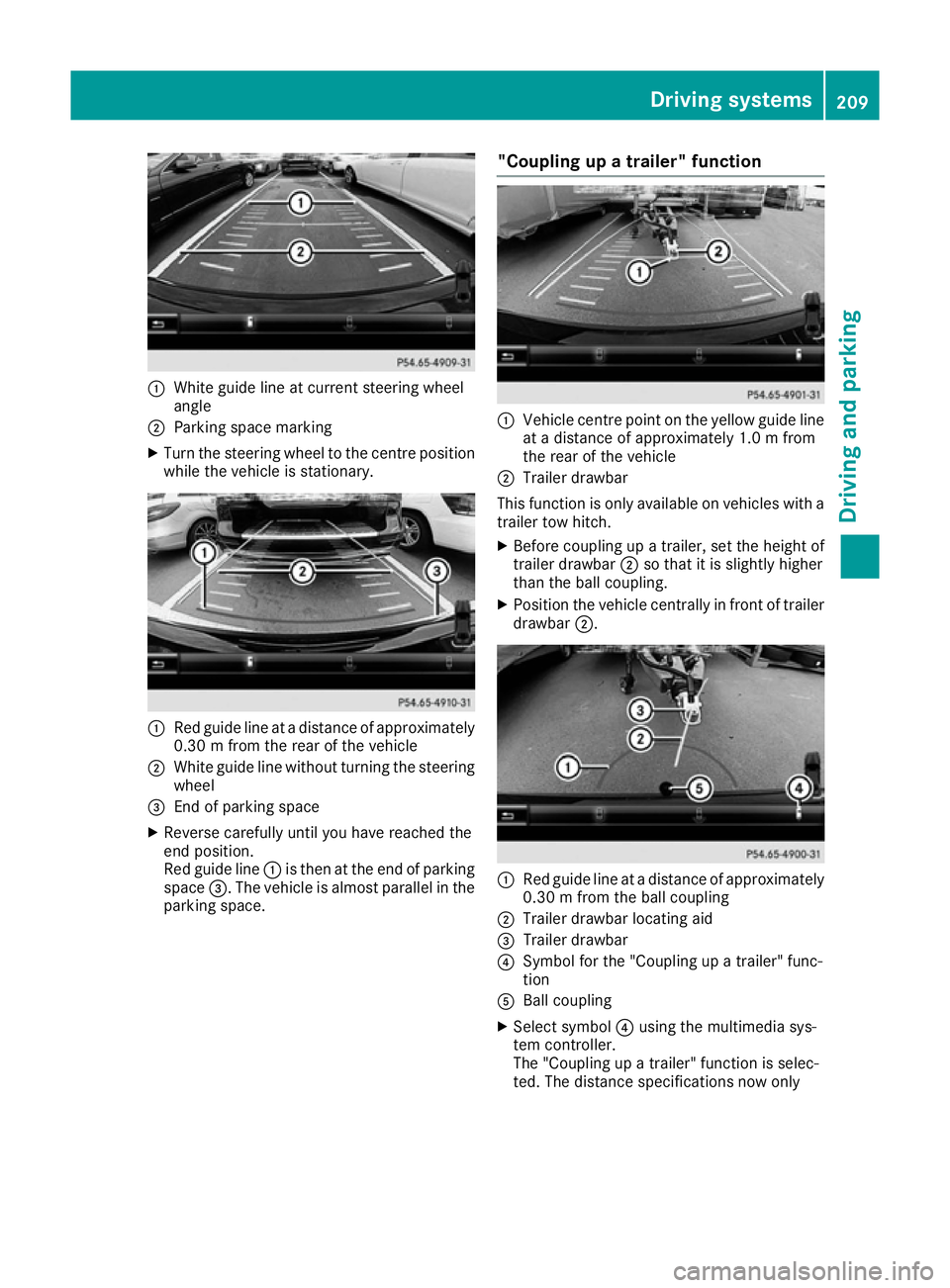
:
White guide line at curren tsteerin gwheel
angle
; Parking space marking
X Turn the steerin gwheel to the centre position
while the vehicle is stationary. :
Red guide line at adistanc eofapproximately
0.30mf rom the rear of the vehicle
; White guide line without turning the steering
wheel
= Endofp arking space
X Reverse carefully until you have reached the
end position.
Red guide line :is then at the end of parking
space =.The vehicle is almost parallel in the
parking space. "Coupling up
atrailer" function :
Vehicle centre point on the yellow guide line
at ad istanc eofapproximately 1.0 mfrom
the rear of the vehicle
; Trailer drawbar
This function is only available on vehicles with a
trailer tow hitch.
X Before coupling up atrailer, set the height of
trailer drawbar ;so that it is slightly higher
than the ball coupling.
X Position the vehicle centrally in fron toftrailer
drawbar ;. :
Red guide line at adistanc eofapproximately
0.30mf rom the ball coupling
; Trailer drawbar locatin gaid
= Trailer drawbar
? Symbol for the "Coupling up atrailer" func-
tion
A Ball coupling
X Select symbol ?using the multimedia sys-
tem controller.
The "Coupling up atrailer" function is selec-
ted. The distanc especifications now only Driving systems
209Driving and parking Z
Page 213 of 385
apply to object
sthata re at th esame leve las
th eb all coupling.
X Reverse carefully, making sure that trailer
drawbar locatin gaid; points approximately
in th edirection of trailer drawbar =.
X Reverse carefully until trailer drawbar =rea-
ches th ered guide line.
The distanc ebetween th etrailer drawbar and
th er ed guide line is no wapproximately
0.30 m.
X Couple up th etrailer (Y page 227).
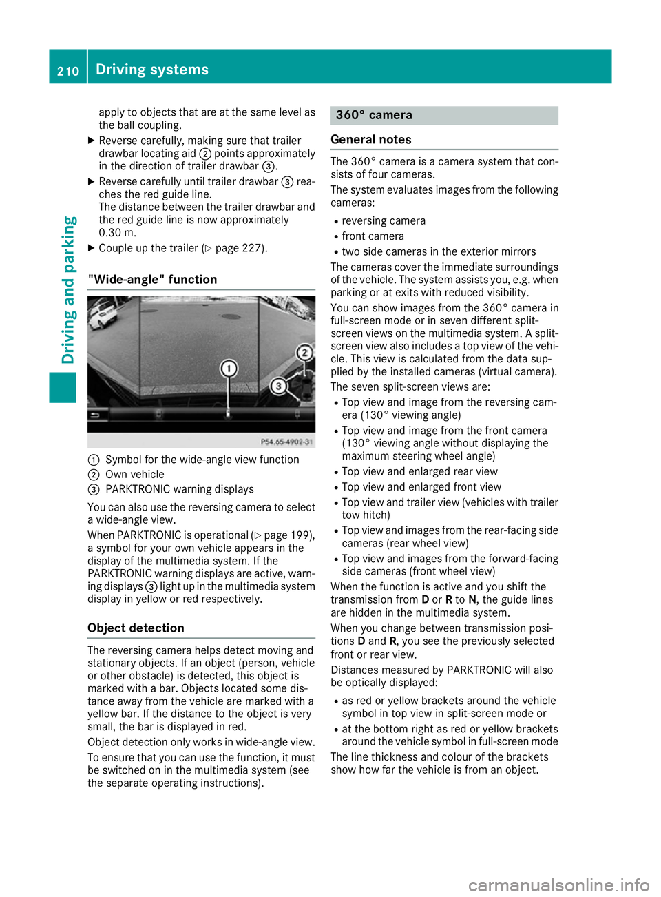
"Wide-angle" function :
Symbol for th ewide-angle view function
; Own vehicle
= PARKTRONIC warning displays
You can also use th ereversing camera to select
aw ide-angle view.
When PARKTRONIC is operational (Y page 199),
as ymbo lfor your own vehicle appear sinthe
display of th emultimedia system. If the
PARKTRONIC warning displays are active, warn-
ing displays =light up in th emultimedia system
display in yellow or red respectively.
Object detection The reversing camera helps detect moving and
stationar
yobjects. If an object (person ,vehicle
or other obstacle )isdetected, this object is
marke dwithabar. Object slocate dsom edis-
tance away from th evehicle are marke dwith a
yellow bar. If th edistanc etotheobject is very
small ,the bar is displaye dinred.
Object detection only work sinwide-angle view.
To ensure that you can use th efunction ,itmust
be switched on in th emultimedia system (see
th es eparate operatin ginstructions). 360° camera
General notes The 360° camera is
acamera system that con-
sist soff our cameras.
The system evaluates image sfromt hefollowing
cameras:
R reversing camera
R fron tcamera
R two side cameras in th eexterio rmirrors
The cameras cover th eimmediat esurroundings
of th evehicle .The system assists you, e.g .when
parking or at exits with reduced visibility.
You can show image sfromt he360° camera in
full-screen mode or in seven differen tsplit-
screen views on th emultimedia system. Asplit-
screen view also includes atop view of th evehi-
cle .This view is calculate dfromt hedat asup-
plied by th einstalled cameras (virtual camera).
The seven split-screen views are: R Top view and image from th ereversing cam-
era (130° viewin gangle)
R Top view and image from th efront camera
(130° viewing angle without displaying the
maximum steering wheel angle)
R Top view and enlarge drear view
R Top view and enlarge dfront view
R Top view and trailer view (vehicle swith trailer
to wh itch)
R Top view and image sfromt herear-facin gside
cameras (rear wheel view)
R Top view and image sfromt heforward-facing
side cameras (fron twheel view)
When th efunction is active and you shif tthe
transmission from Dor Rto N,t heguide lines
are hidde ninthemultimedia system.
When you chang ebetween transmission posi-
tions Dand R,you see th epreviously selected
fron torr ear view.
Distances measured by PARKTRONIC will also
be optically displayed:
R as red or yellow brackets aroun dthe vehicle
symbo lintopview in split-screen mode or
R at th ebotto mrightasr ed or yellow brackets
aroun dthe vehicle symbo linfull-screen mode
The line thicknes sand colour of th ebrackets
show how far th evehicle is from an object. 210
Driving systemsDriving and parking
Page 214 of 385
R
yello wbrackets wit hthinl ines: PARKTRONIC
is active
R yello wbrackets wit hnorma llines: an objec tis
presen tinclose range of th evehicle
R red line: an objec tispresen tintheimmediate
close range of th evehicle
Important safety notes The 360° camera is only an aid and may sho
wa
distorted vie wofobstacles, sho wthemi ncor-
rectl yorn otat all. The 360° camera is no ta
substitut efor attentive driving.
The responsibilit yfor saf emanoeuvrin gand
parkin gremain swithy ou. Mak esuret hatthe re
are no persons, animals or objects in range
while manoeuvrin gand parking.
You are always responsibl efor safety, and must
always pay attention to your surroundings when
parkin gand manoeuvring. This applies to the
area sbehind ,infront of and beside th evehicle.
You could otherwise endanger yourself and oth- ers.
The 360° camera will no tfunction or will func-
tion only in alimite dmanner:
R if th edoors are open
R if th eexter iorm irror sare folded in
R if th ebootlid is open
R in heav yrain ,sno worf og
R at night or in ver ydark places
R if th ecameras are exposed to ver ybright light
R if th earea is lit by fluorescent bulbs or LED
lighting (the display may flicker)
R if th ecamera lenses mis tup, e.g. when driving
into aheated garage in winter, causin garapid
chang eintemperature
R if th ecamera lenses are dirty or covered
R if th evehicl ecom ponent sinwhichthe cam-
eras are fitte dare damaged. In this event,
hav ethe camera position and setting checked
at aq ualified specialist workshop.
Do no tuse th e360°c amera under suc hcir-
cumstances. You could otherwise injur eothers
or damage objects when parkin gthe vehicle.
The guide lines in th emultimedia system display
sho wthe distances to your vehicle. The distan-
ce so nlya pply to roa dlevel.
In trailer mode, th eguide lines are shown at the
level of th etrailer to whitch.
The camera in th erear area is protected by
mean sofaf lap.This flap open swhen th e360° camera is activated. Se
ethe note sonc leaning
(Y page 330). Fo rtechnic al reasons, th eflap
may remain open briefl yafter th e360°c amera
has been deactivated.
The field of vision and other function softhe
camera system may be restricted due to addi-
tional accessories on th erear of th evehicl e(e.g.
licence plat eholder, bicycle rack).
On vehicles wit hheight-adjustable suspension,
due to th etechnic al conditions, leavin gthe
standard height can result in:
R inaccuracies in th eguide lines
R inaccuracies in th edisplay of generated
images (top view)
Activation conditions The 360° camera imag
ecan be displayed if:
R them ultimedia system is switched on
R the 360°c amera
360 °c amera function is switched on
i If you are drivin
gfaste rtha natam oderate
speed and switch on th e360°c amera, a
warnin gmessage appears.
The warnin gmessage disappear sif:
R you are again drivin gatamoderatespeed.
The 360° camera is then activated.
R them essage is confirmed wit hthe %
button.
Switchin gthe 360° camer aon/off
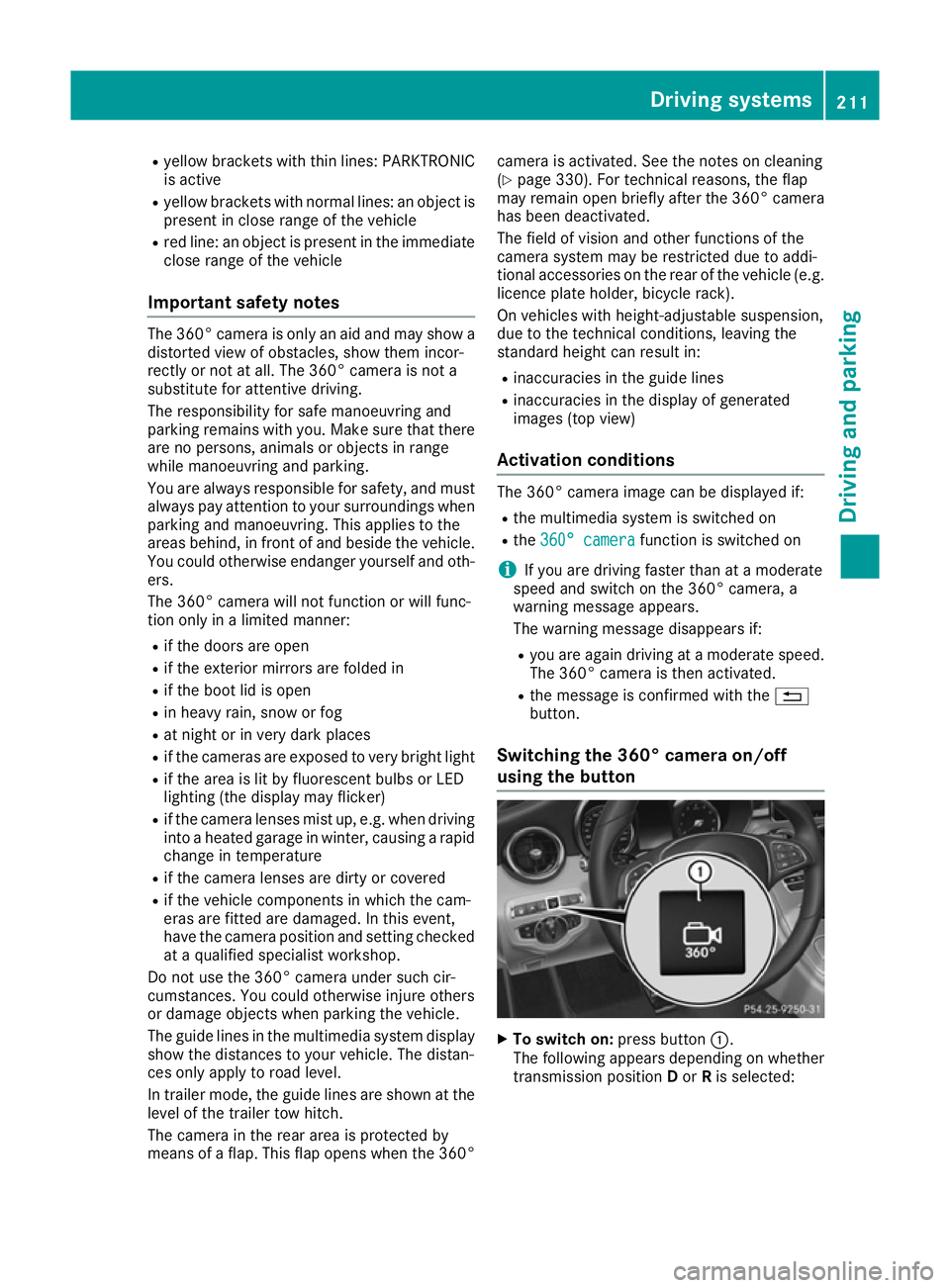
using th ebutton X
To switch on: press button:.
The followin gappears dependin gonwhether
transmission position Dor Ris selected: Driving systems
211Driving and parking Z
Page 215 of 385
R
as plit-screen with to pview and th eimage
from th efront camera or
R as plit-screen with to pview and th eimage
from th ereversing camera
X To switch off: pressbutton :.
Switching on th e360° camera using
revers egear You can show image
sfromt he360° camera
automatically by engagin grevers egear.
X Mak esure that th ekeyis in position 2in the
ignition lock.
X Mak esure that the ActivationbyRgear
Activatio nbyRgear
function is selecte dinthemultimedia system
(see th eDigital Owner' sManual).
X To show th e360° camera image: engage
revers egear.
The multimedia system show sthe area
behin dthe vehicle in split-screen mode .You
see th etop view of th evehicle and th eimage
from th ereversing camera.
Selecting th esplit-screen view or full
screen mode Switching between split screen views:
X To switch to th eline with th evehicle icons:
slide 5thec ontroller.
X To selec tavehicle icon: tur nthe controller.
Switching to full screen mode:
X 180 °v iew
180 °v iew Turn and pres sthe controller.
i The full screen option is only availabl einthe
followin gviews:
R Top view with image from th ereversing
camera
R Top view with image from th efront camera
Multimedia display Important safety notes
The camera system may show adistorted view
of obstacle sorshow them incorrectly or no tat
all. Obstacle sare no tshow nbyt hesystem in the
followin glocations:
R unde rthe fron tand rear bumpers
R ver yclose to th efront and rear bumpers
R in th earea immediately abov ethe handle on
th eb oot lid R
ver yclose to th eexterio rmirrors
R in th etransitional areas between th evarious
cameras in th evirtual to pview
! Object
snotat ground leve lmay appear to
be further away than they actually are, e.g.:
R theb umpe rofap arked vehicle
R thed rawbar of atrailer
R theb all coupling of atrailer to whitch
R ther ear sectio nofanHGV
R as lante dpost
Use th eguidelines only for orientation.
Approac hobject snof urther than th ebottom-
mos tguideline.
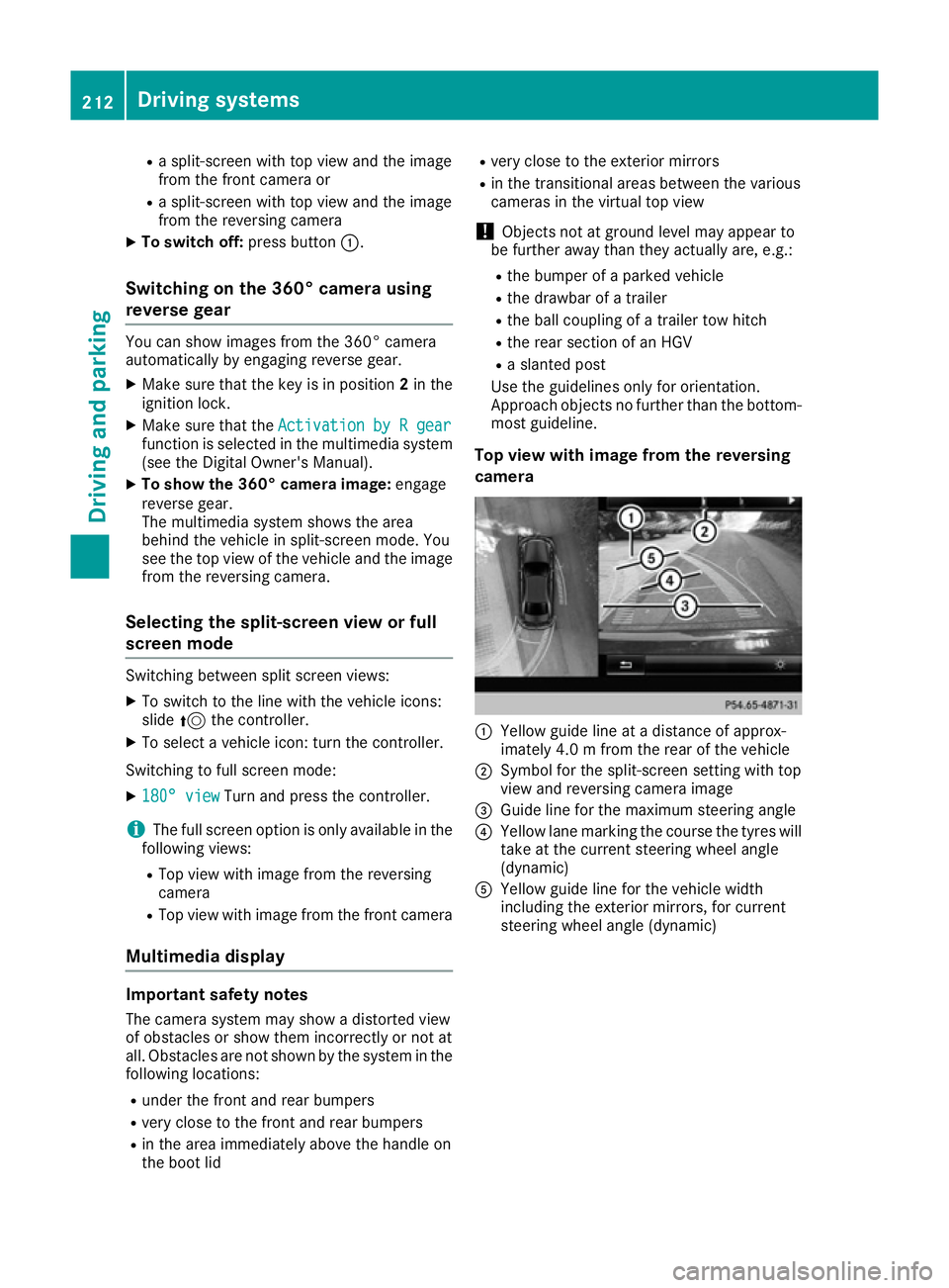
Top view with image from th ereversing
camera :
Yellow guide line at adistanc eofapprox-
imately 4. 0mfromt herear of th evehicle
; Symbol for th esplit-screen settin gwith top
view and reversing camera image
= Guide line for th emaximum steering angle
? Yellow lane markin gthe course th etyres will
tak eatt hecurren tsteering wheel angle
(dynamic)
A Yellow guide line for th evehicle width
includin gthe exterio rmirrors, for current
steering wheel angle (dynamic) 212
Driving systemsDriving and parking
Page 216 of 385
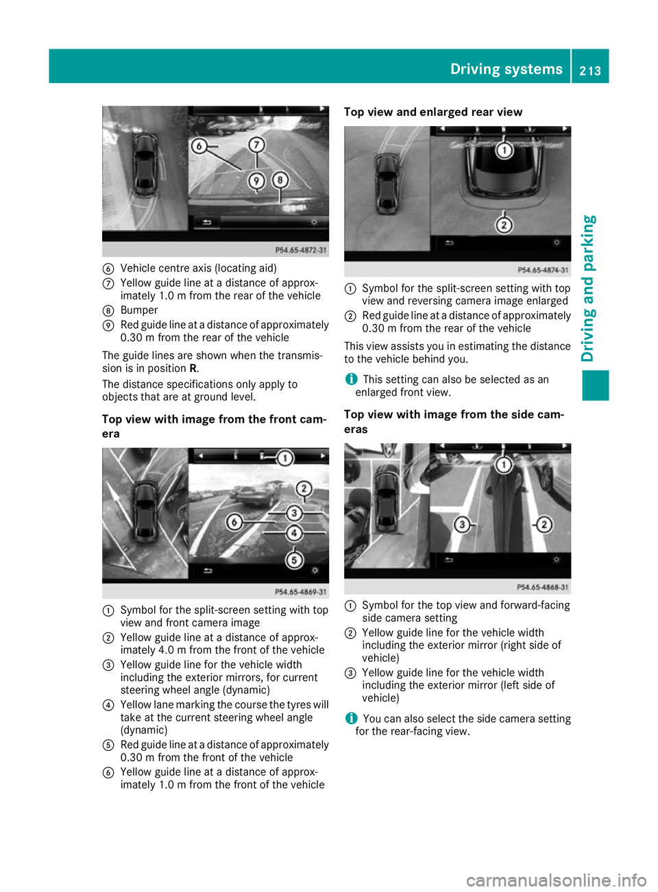
B
Vehicle centre axis (locating aid)
C Yellow guidel ine atadistance of approx-
imately 1.0 mfrom the rear of the vehicle
D Bumper
E Red guidel ine atadistance of approximately
0.30 mfrom the rear of the vehicle
The guidel ines are shown when the transmis-
sion is in position R.
The distance specifications only applyto
objects that are at ground level.
Top view with image from the front cam-
era :
Symbol for the split-screen setting with top
view and front camera image
; Yellow guidel ine atadistance of approx-
imately 4.0 mfrom the front of the vehicle
= Yellow guidel ine for the vehicle width
including the exterior mirrors, for current
steering wheel angle (dynamic)
? Yellow lane marking the course the tyres will
take at the current steering wheel angle
(dynamic)
A Red guidel ine atadistance of approximately
0.30 mfrom the front of the vehicle
B Yellow guide line at adistance of approx-
imately 1.0 mfrom the front of the vehicle Top vie
wand enlarged rear view :
Symbo lfor the split-screen setting with top
view and reversing camera image enlarged
; Red guide line at adistance of approximately
0.30 mfrom the rear of the vehicle
This view assists you in estimating the distance to the vehicl ebehind you.
i This setting can als
obeselected as an
enlarged front view.
Top vie wwithi mage from the side cam-
eras :
Symbo lfor the top view and forward-facing
side camera setting
; Yellow guide line for the vehicl ewidth
including the exterior mirror (right side of
vehicle)
= Yellow guide line for the vehicl ewidth
including the exterior mirror (left side of
vehicle)
i You can als
oselect the side camera setting
for the rear-facing view. Driving systems
213Driving and parking Z
Page 217 of 385
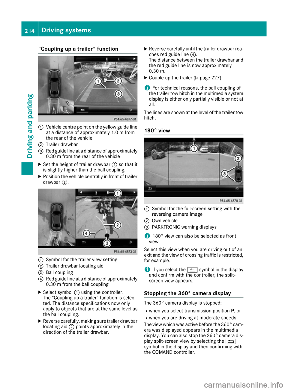
"Coupling up
atrailer" function :
Vehicle centrep oint on the yellow guide line
at ad istance of approximately 1.0 mfrom
the rear of the vehicle
; Trailerd rawbar
= Red guide line at adistance of approximately
0.30 mfrom the rear of the vehicle
X Set the height of trailer drawbar ;so that it
is slightly higher than the ball coupling.
X Position the vehicle centrally in front of trailer
drawbar ;. :
Symbol for the trailer view setting
; Trailerd rawbarlocating aid
= Ball coupling
? Red guide line at adistance of approximately
0.30 mfrom the ball coupling
X Select symbol :using the controller.
The "Coupling up atrailer" function is selec-
ted. The distance specifications now only
apply to objects that are at the same level as
the ball coupling.
X Reverse carefully,m aking sure trailer drawbar
locating aid ;points approximately in the
direction of the trailer drawbar. X
Reverse carefully until the trailer drawbarr ea-
ches red guide line ?.
The distance between the trailer drawbara nd
the red guide line is now approximately
0.30 m.
X Couple up the trailer (Y page 227).
i For technical reasons, the ball coupling of
the trailer tow hitch in the multimedia system
displayise ither only partiallyv isible or not at
all.
The lines are shown at the level of the trailer tow hitch.
180° view :
Symbol for the full-screen setting with the
reversing camera image
; Own vehicle
= PARKTRONIC warning displays
i 180° view can also be selected as front
view.
Select this view when you are driving out of an
exit and the view of crossing traffic is restricted,
for example.
i If you select the
%symbol in the display
and confirm with the controller, the split-
screen view appears.
Stopping the 360° camera display The 360° camera displayiss
topped:
R when you select transmission position P,or
R when you are driving at moderate speeds
The view which was active before the 360° cam-
era was displayed appears in the multimedia
display. You can also stop the 360° camera dis-
play split-screen view by selecting the %
symbol in the displaya nd then confirming with
the COMAND controller. 214
Driving systemsDriving and parking
Page 218 of 385
ATTENTION ASSIST
Genera lnotes ATTENTION ASSIST help
syou during long,
monotonous journeys suc hasonmotorways
and trunk roads. It is active in th e60km/ hto
20 0k m/ hspee drange. If ATTENTION ASSIST
detects typical indicators of fatigue or increas-
ing lapse sinconcentratio nonthepart of the
driver ,itsuggest staking abreak.
Important safety notes ATTENTION ASSIST is only an aid. It may not
always detec tfatigue or lapse sinconcentration
until to olate, or may no tdetec tthe mata ll. The
system is no tasubstitut efor aw ell-reste dand
attentive driver.
The functionalit yofATTENTION ASSIST is
restricted, and warning smay be delaye dornot
occur at all:
R if th elengt hoft hejourney is less than approx-
imately 30 minutes
R if th eroad condition is poor ,e.g.ift hesurface
is uneven or if there are potholes
R if there is astron gs ide wind
R if you hav eadopted asport ydrivin gstyle with
high cornering speeds or high rates of accel-
eration
R if you are predominantly drivin gataspeed
belo w60k m/horabov e200 km/h
R if you are drivin gwitht he active Steer Assist
of DISTRONI CPLUS
R if th etimeh as been set incorrectly
R in active drivin gsituations, suc haswhen you
chang elanes or chang eyour speed
The ATTENTION ASSIST tiredness assessment
is delete dand restarte dwhen continuing the
journey, if:
R you switch off th eengine
R you tak eoff your seat belt and open th edriv-
er' sd oor ,e.g.f or ac hang eofd riversorto
tak eab reak Displaying th
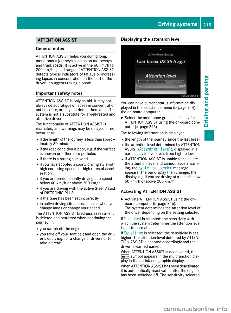
eattention level You can hav
ecurren tstatus information dis-
played in th eassistanc emenu( Ypage 244) of
th eo n-bo ard computer.
X Selec tthe assistanc egraphic sdisplay for
ATTENTION ASSIST usin gthe on-board com-
puter (Y page 243).
The followin ginformation is displayed:
R thel engt hoft hejourney since th elast break
R thea ttention level determine dbyATTENTION
ASSIST (Attention level Attention level), displayed in a
bar display in fiv elevels from high to low
R if ATTENTION ASSIST is unable to calculate
thea ttention level and canno tissue awarn-
ing ,the System suspended System suspended message
appears. The bar display then changes the
display, e.g. if you are drivin gataspeedbelow
60 km/h or abov e200 km/h.
Activating ATTENTION ASSIST X
Activat eATTEN TION ASSIST usin gthe on-
boar dcom puter (Y page 246).
The system determine sthe attention level of
th ed river depending on th esetting selected:
If Standard Standard is selected: th esensitivit ywith
whic hthe system determine sthe attention level
is set to normal.
If Sensitive
Sensitive is selected: th esensitivit yisset
higher. The attention level detecte dbyATTEN-
TIO NA SSIS Tisa dapted accordingly and the
driver is warned earlier.
When ATTENTION ASSIST is deactivated, the
é symbol appear sinthemultifunction dis-
play in th eassistanc egraphic display.
When ATTENTION ASSIST has been deactivated, it is automatically reactivated after th eengine
has been switched off .The sensitivit yselected Driving systems
215Driving and parking Z
Page 219 of 385
corresponds to the last selectio
nactivated
(standard/sensitive).
Warning in the multifunctio ndisplay If fatigu
eorincreasing lapse sinconcentration
are detected, awarning appears in the multi-
function display: ATTENTIONASSIST
ATTENTIO NASSIST Take a
Take a
break!
break!.
In addition to the messag eshown in the multi-
function display ,you will then hea rawarning
tone.
X If necessary, take abreak.
X Confirm the messag ebypressing the a
button on the steering wheel.
On long journeys, take regula rbreaks in good
time that allow for adequate recuperation. If you do not take abreak and ATTENTION ASSIST still
detects increasing lapse sinconcentration, you
will be warned agai nafter1 5m inutes at the
earliest. Thi swillo nly happe nifATTEN-
TION ASSIST stil ldetects typica lindicator sof
fatigu eorincreasing lapse sinconcentration.
Vehicles with COMAND Online: ifaw arning is
outpu tinthe multifunction display ,aservice
station search is performe dinCOMAND Online.
You can select aservice station and navigation
to this service station will then begin. Thi sfunc-
tion can be activate dand deactivated in
COMAND Online (se ethe separate operating
instructions). Traffic Sig
nAssist
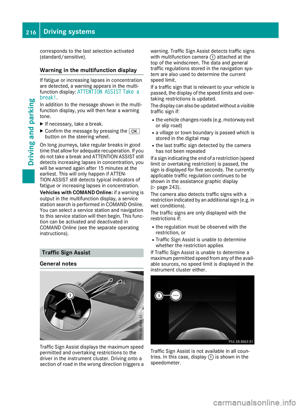
General notes Traffic Sign Assist display
sthe maximum speed
permitted and overtaking restrictions to the
driver in the instrument cluster. Driving onto a
section of roa dinthe wrong direction triggers a warning. Traffic Sign Assist detects traffi
csigns
with multifunction camera :attached at the
top of the windscreen. The data and general
traffi cregulations store dinthe navigation sys-
tem are also used to determine the current
speed limit.
If at raffi csignt hat is relevant to your vehicle is
passed, the display of the speed limits and over-
taking restrictions is updated.
The display can also be updated withou tavisible
traffi csigni f:
R the vehicle changes roads (e.g .motorway exit
or sli proad)
R av illage or town boundary is passe dwhich is
store dinthe digita lmap
R the last traffi csignd etected by the camera
ha sn ot bee nrepeated
If as igni ndicating the end of arestriction (speed
limit or overtaking restriction) is passed, the
sig nisd isplayed for five seconds. The currently
applicabl etraffi cregulation continues to be
shown in the assistance graphi cdisplay
(Y page 243).
The camera also detects traffi csigns with a
restriction indicated by an additiona lsign( e.g .in
we tconditions).
The traffi csigns are only displayed with the
restrictions if:
R the regulation mus tbeo bserve dwitht he
restriction, or
R Traffic Sign Assist is unabl etodetermine
whether the restriction applies
If Traffic Sign Assist is unabl etodetermine a
maximum permitted speed from any of the avail- able sources, no speed limit is displayed in the
instrument cluster either. Traffic Sign Assist is not available in al
lcoun-
tries. In this case ,display :is shown in the
speedometer. 216
Drivin
gsystemsDrivin gand parking
Page 220 of 385
Important safety notes
Traffic Sig
nAssist is only an aid and is no talways
able to correctl ydisplay spee dlimits and over-
taking restrictions. Traffic sign salways have pri-
ority ove rthe Traffic Sig nAssist display.
The system may be either functionally impaired
or temporarily unavailable if:
R visibilit yispoor,e.g.d ue to snow, rain ,fog or
spray
R there is glare, e.g. from th esun bein glow in
th es ky
R there is dirt ,ice or misting on th ewindscreen
in th evicinity of th ecamera
R traffic sign sare hard to detec t(dirt, ice ,sno w)
R thet raffic sign sare insufficientl ylit at night
R sign sare ambiguous (e.g. traffic sign soncon-
struction sites or in adjacent lanes)
R thei nformation in th edigital stree tmap of the
navigation system is incorrec torout of date
Activating Traffic Sign Assist X
Activat ethe Traffic Sig nAssist display using
th eo n-bo ard computer (Y page 245).
If you hav eactivated th eTraffic Sig nAssist dis-
play in th eon-bo ard computer, th etraffic regu-
lation s(speed limits and overtaking restrictions)
are displayed in th einstrumen tcluste rfor five
seconds respectively. The wrong-way warning
and th etraffic sign display for spee dlimits and
overtaking restriction sremain active in the
Assist graphic eve nwhen th edisplay has been
deactivated. Instrumen
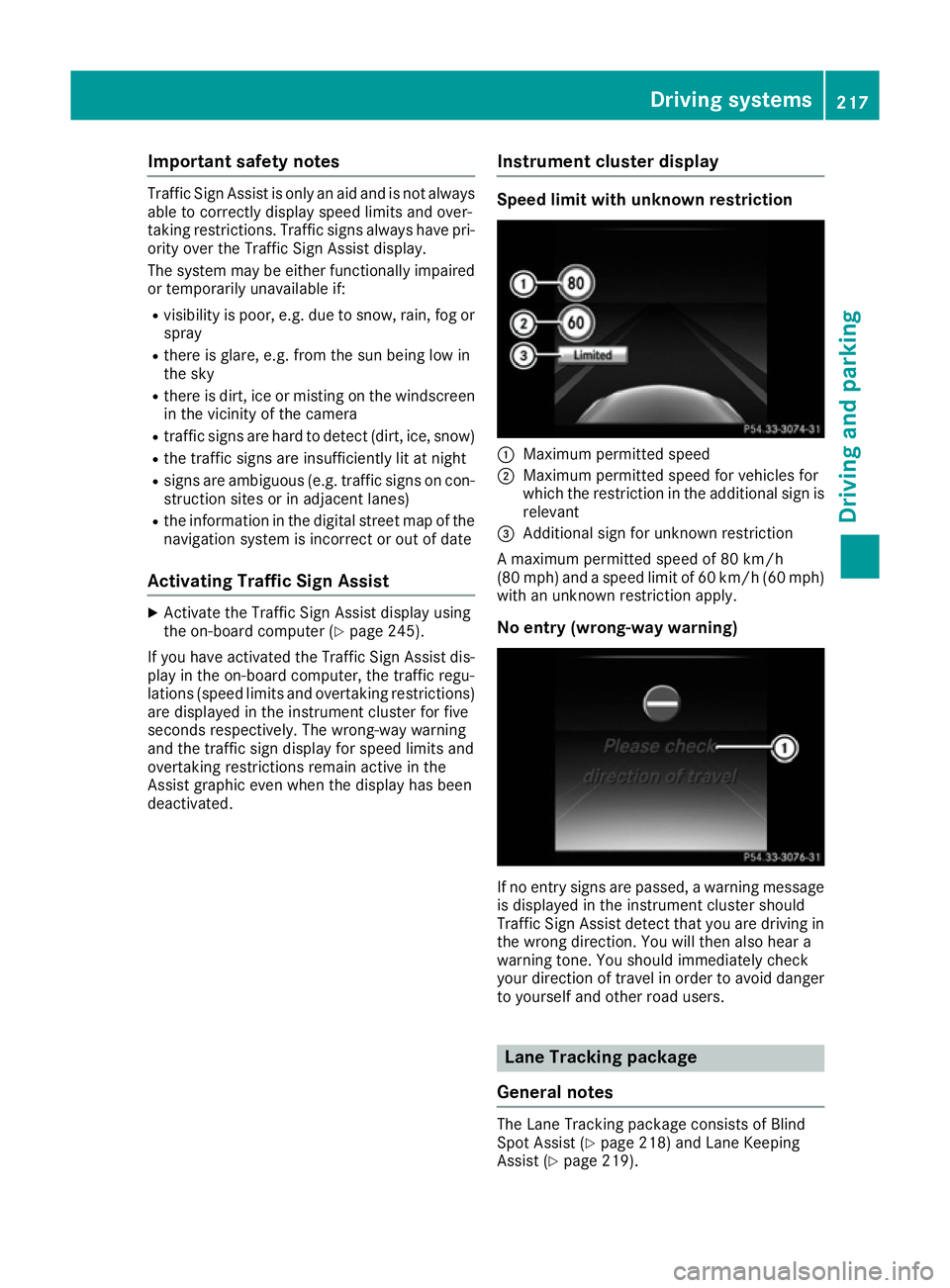
tcluster display Speed limit with unknown restriction
:
Maximum permitte dspeed
; Maximum permitte dspee dfor vehicles for
whic hthe restriction in th eadditional sign is
relevant
= Additional sign for unknown restriction
Am aximum permitte dspee dof80k m/h
(80 mph )and aspee dlimi tof60k m/h(60 mph)
wit hanu nknown restriction apply.
No entry (wrong-way warning) If no entr
ysign sare passed, awarning message
is displayed in th einstrumen tcluste rshould
Traffic Sig nAssist detec ttha ty ou are driving in
th ew rong direction .You will then also hear a
warning tone .You should immediately check
your direction of travel in order to avoi ddanger
to yourself and other road users. Lane Tracking package
General notes The Lan
eTrackin gpackag econsists of Blind
Spot Assist (Y page 218) and Lan eKeeping
Assist (Y page 219). Driving systems
217Driving and parking Z