MERCEDES-BENZ SPRINTER 2005 Service Repair Manual
Manufacturer: MERCEDES-BENZ, Model Year: 2005, Model line: SPRINTER, Model: MERCEDES-BENZ SPRINTER 2005Pages: 1232, PDF Size: 39.23 MB
Page 891 of 1232
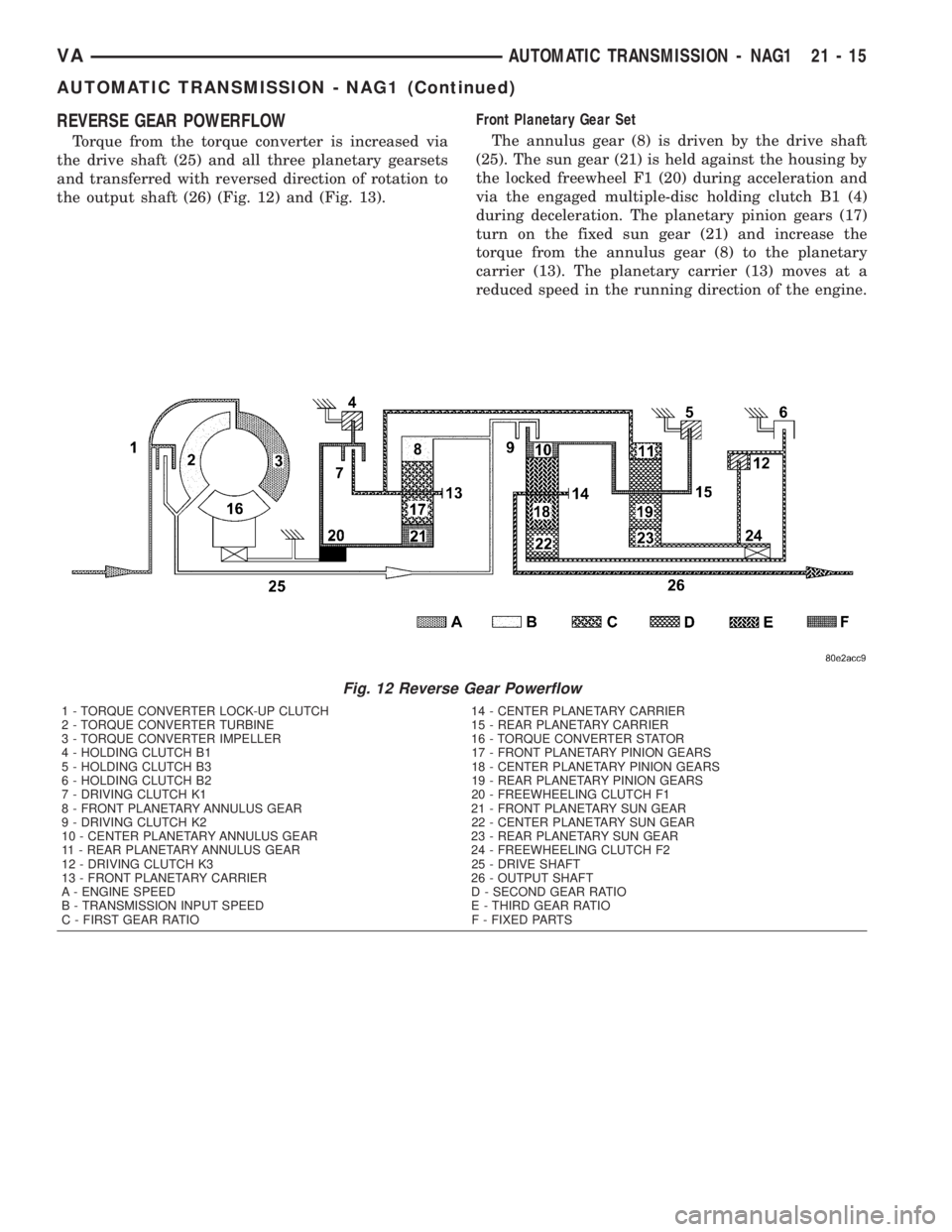
REVERSE GEAR POWERFLOW
Torque from the torque converter is increased via
the drive shaft (25) and all three planetary gearsets
and transferred with reversed direction of rotation to
the output shaft (26) (Fig. 12) and (Fig. 13).Front Planetary Gear Set
The annulus gear (8) is driven by the drive shaft
(25). The sun gear (21) is held against the housing by
the locked freewheel F1 (20) during acceleration and
via the engaged multiple-disc holding clutch B1 (4)
during deceleration. The planetary pinion gears (17)
turn on the fixed sun gear (21) and increase the
torque from the annulus gear (8) to the planetary
carrier (13). The planetary carrier (13) moves at a
reduced speed in the running direction of the engine.
Fig. 12 Reverse Gear Powerflow
1 - TORQUE CONVERTER LOCK-UP CLUTCH 14 - CENTER PLANETARY CARRIER
2 - TORQUE CONVERTER TURBINE 15 - REAR PLANETARY CARRIER
3 - TORQUE CONVERTER IMPELLER 16 - TORQUE CONVERTER STATOR
4 - HOLDING CLUTCH B1 17 - FRONT PLANETARY PINION GEARS
5 - HOLDING CLUTCH B3 18 - CENTER PLANETARY PINION GEARS
6 - HOLDING CLUTCH B2 19 - REAR PLANETARY PINION GEARS
7 - DRIVING CLUTCH K1 20 - FREEWHEELING CLUTCH F1
8 - FRONT PLANETARY ANNULUS GEAR 21 - FRONT PLANETARY SUN GEAR
9 - DRIVING CLUTCH K2 22 - CENTER PLANETARY SUN GEAR
10 - CENTER PLANETARY ANNULUS GEAR 23 - REAR PLANETARY SUN GEAR
11 - REAR PLANETARY ANNULUS GEAR 24 - FREEWHEELING CLUTCH F2
12 - DRIVING CLUTCH K3 25 - DRIVE SHAFT
13 - FRONT PLANETARY CARRIER 26 - OUTPUT SHAFT
A - ENGINE SPEED D - SECOND GEAR RATIO
B - TRANSMISSION INPUT SPEED E - THIRD GEAR RATIO
C - FIRST GEAR RATIO F - FIXED PARTS
VAAUTOMATIC TRANSMISSION - NAG1 21 - 15
AUTOMATIC TRANSMISSION - NAG1 (Continued)
Page 892 of 1232
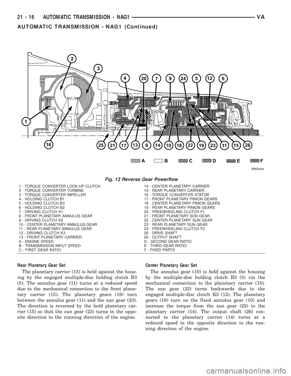
Rear Planetary Gear Set
The planetary carrier (15) is held against the hous-
ing by the engaged multiple-disc holding clutch B3
(5). The annulus gear (11) turns at a reduced speed
due to the mechanical connection to the front plane-
tary carrier (13). The planetary gears (19) turn
between the annulus gear (11) and the sun gear (23).
The direction is reversed by the held planetary car-
rier (15) so that the sun gear (23) turns in the oppo-
site direction to the running direction of the engine.Center Planetary Gear Set
The annulus gear (10) is held against the housing
by the multiple-disc holding clutch B3 (5) via the
mechanical connection to the planetary carrier (15).
The sun gear (22) turns backwards due to the
engaged multiple-disc clutch K3 (12). The planetary
gears (18) turn on the fixed annulus gear (10) and
increase the torque from the sun gear (22) to the
planetary carrier (14). The output shaft (26) con-
nected to the planetary carrier (14) turns at a
reduced speed in the opposite direction to the run-
ning direction of the engine.
Fig. 13 Reverse Gear Powerflow
1 - TORQUE CONVERTER LOCK-UP CLUTCH 14 - CENTER PLANETARY CARRIER
2 - TORQUE CONVERTER TURBINE 15 - REAR PLANETARY CARRIER
3 - TORQUE CONVERTER IMPELLER 16 - TORQUE CONVERTER STATOR
4 - HOLDING CLUTCH B1 17 - FRONT PLANETARY PINION GEARS
5 - HOLDING CLUTCH B3 18 - CENTER PLANETARY PINION GEARS
6 - HOLDING CLUTCH B2 19 - REAR PLANETARY PINION GEARS
7 - DRIVING CLUTCH K1 20 - FREEWHEELING CLUTCH F1
8 - FRONT PLANETARY ANNULUS GEAR 21 - FRONT PLANETARY SUN GEAR
9 - DRIVING CLUTCH K2 22 - CENTER PLANETARY SUN GEAR
10 - CENTER PLANETARY ANNULUS GEAR 23 - REAR PLANETARY SUN GEAR
11 - REAR PLANETARY ANNULUS GEAR 24 - FREEWHEELING CLUTCH F2
12 - DRIVING CLUTCH K3 25 - DRIVE SHAFT
13 - FRONT PLANETARY CARRIER 26 - OUTPUT SHAFT
A - ENGINE SPEED D - SECOND GEAR RATIO
B - TRANSMISSION INPUT SPEED E - THIRD GEAR RATIO
C - FIRST GEAR RATIO F - FIXED PARTS
21 - 16 AUTOMATIC TRANSMISSION - NAG1VA
AUTOMATIC TRANSMISSION - NAG1 (Continued)
Page 893 of 1232
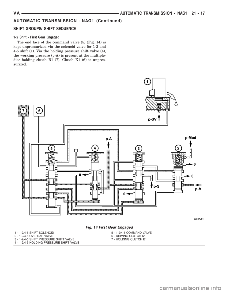
SHIFT GROUPS/ SHIFT SEQUENCE
1-2 Shift - First Gear Engaged
The end face of the command valve (5) (Fig. 14) is
kept unpressurized via the solenoid valve for 1-2 and
4-5 shift (1). Via the holding pressure shift valve (4),
the working pressure (p-A) is present at the multiple-
disc holding clutch B1 (7). Clutch K1 (6) is unpres-
surized.
Fig. 14 First Gear Engaged
1 - 1-2/4-5 SHIFT SOLENOID 5 - 1-2/4-5 COMMAND VALVE
2 - 1-2/4-5 OVERLAP VALVE 6 - DRIVING CLUTCH K1
3 - 1-2/4-5 SHIFT PRESSURE SHIFT VALVE 7 - HOLDING CLUTCH B1
4 - 1-2/4-5 HOLDING PRESSURE SHIFT VALVE
VAAUTOMATIC TRANSMISSION - NAG1 21 - 17
AUTOMATIC TRANSMISSION - NAG1 (Continued)
Page 894 of 1232
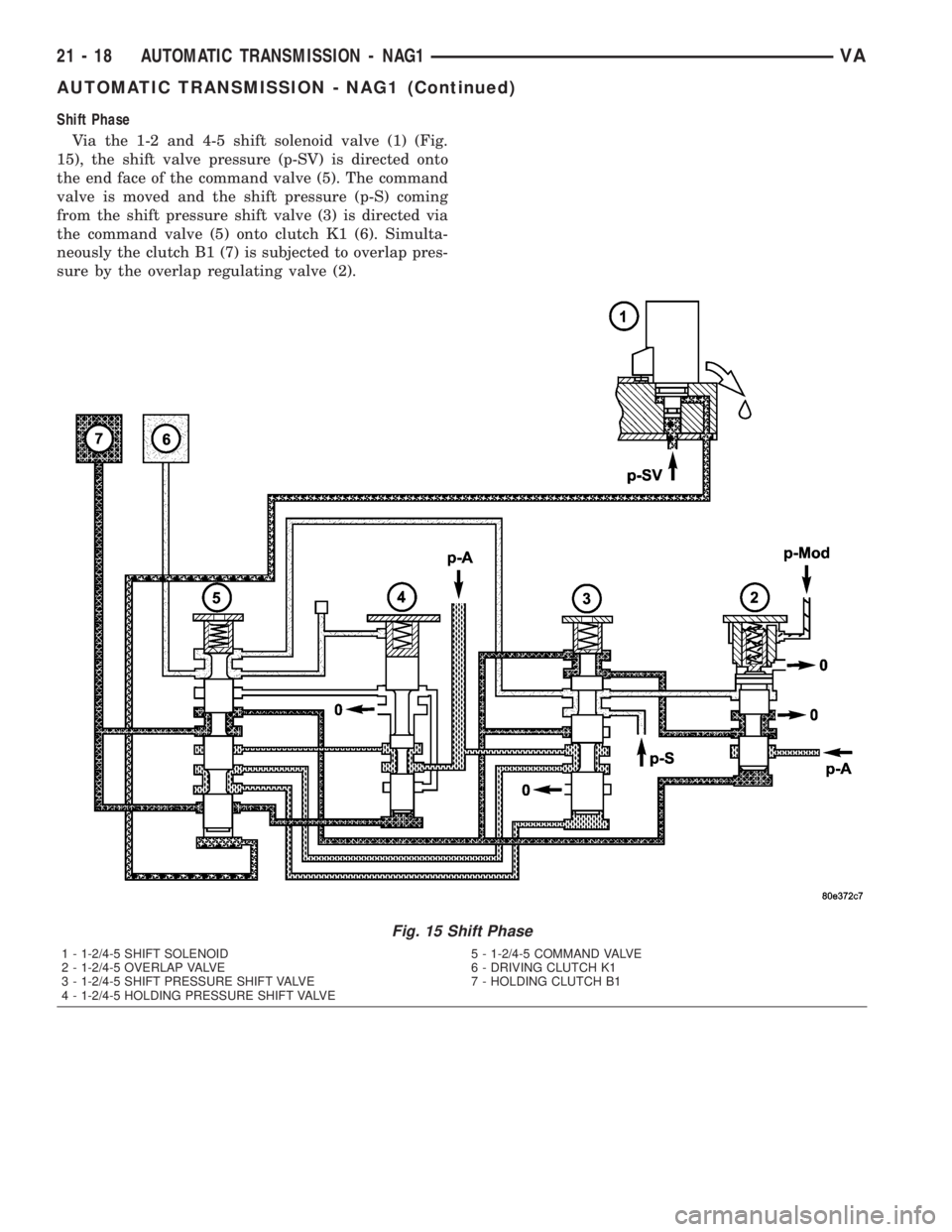
Shift Phase
Via the 1-2 and 4-5 shift solenoid valve (1) (Fig.
15), the shift valve pressure (p-SV) is directed onto
the end face of the command valve (5). The command
valve is moved and the shift pressure (p-S) coming
from the shift pressure shift valve (3) is directed via
the command valve (5) onto clutch K1 (6). Simulta-
neously the clutch B1 (7) is subjected to overlap pres-
sure by the overlap regulating valve (2).
Fig. 15 Shift Phase
1 - 1-2/4-5 SHIFT SOLENOID 5 - 1-2/4-5 COMMAND VALVE
2 - 1-2/4-5 OVERLAP VALVE 6 - DRIVING CLUTCH K1
3 - 1-2/4-5 SHIFT PRESSURE SHIFT VALVE 7 - HOLDING CLUTCH B1
4 - 1-2/4-5 HOLDING PRESSURE SHIFT VALVE
21 - 18 AUTOMATIC TRANSMISSION - NAG1VA
AUTOMATIC TRANSMISSION - NAG1 (Continued)
Page 895 of 1232
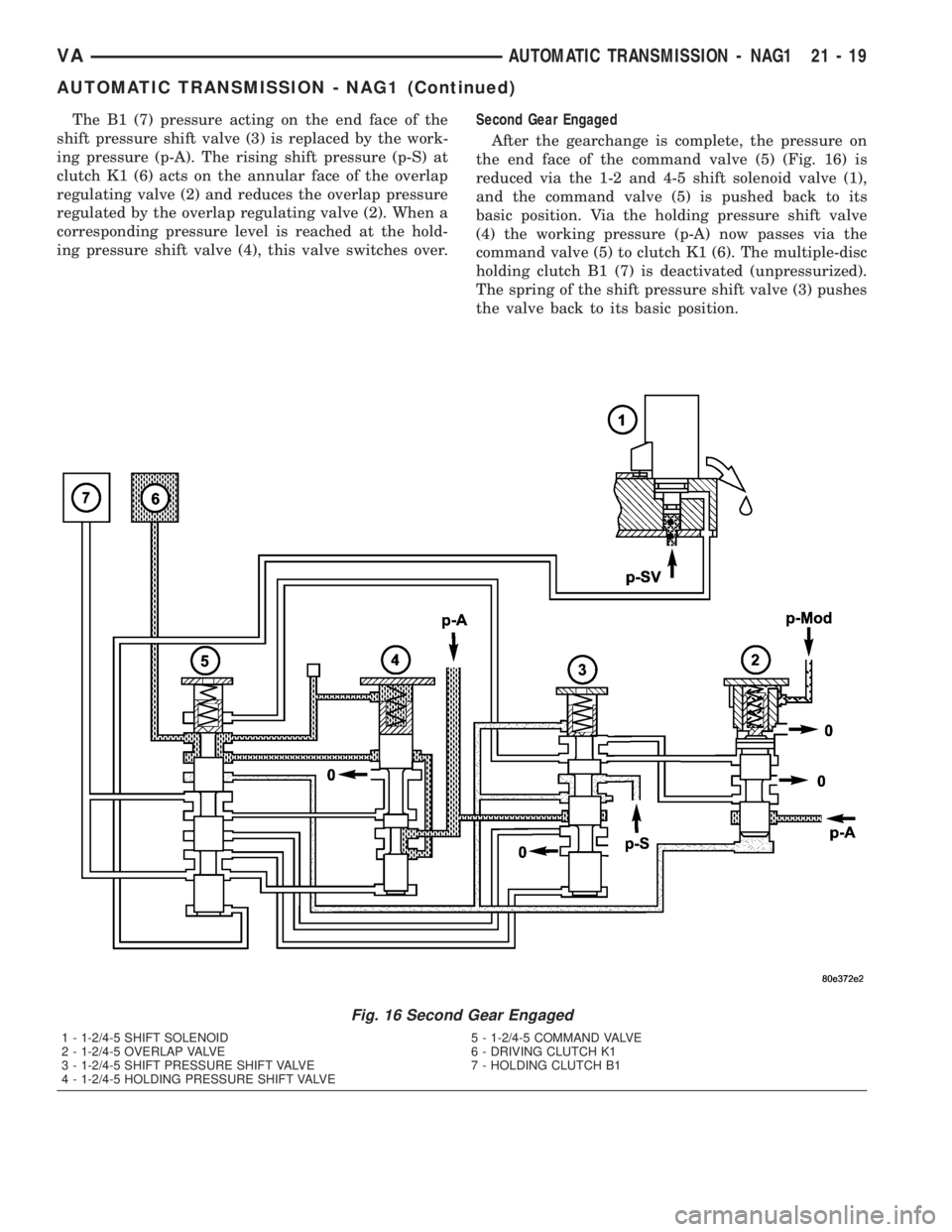
The B1 (7) pressure acting on the end face of the
shift pressure shift valve (3) is replaced by the work-
ing pressure (p-A). The rising shift pressure (p-S) at
clutch K1 (6) acts on the annular face of the overlap
regulating valve (2) and reduces the overlap pressure
regulated by the overlap regulating valve (2). When a
corresponding pressure level is reached at the hold-
ing pressure shift valve (4), this valve switches over.Second Gear Engaged
After the gearchange is complete, the pressure on
the end face of the command valve (5) (Fig. 16) is
reduced via the 1-2 and 4-5 shift solenoid valve (1),
and the command valve (5) is pushed back to its
basic position. Via the holding pressure shift valve
(4) the working pressure (p-A) now passes via the
command valve (5) to clutch K1 (6). The multiple-disc
holding clutch B1 (7) is deactivated (unpressurized).
The spring of the shift pressure shift valve (3) pushes
the valve back to its basic position.
Fig. 16 Second Gear Engaged
1 - 1-2/4-5 SHIFT SOLENOID 5 - 1-2/4-5 COMMAND VALVE
2 - 1-2/4-5 OVERLAP VALVE 6 - DRIVING CLUTCH K1
3 - 1-2/4-5 SHIFT PRESSURE SHIFT VALVE 7 - HOLDING CLUTCH B1
4 - 1-2/4-5 HOLDING PRESSURE SHIFT VALVE
VAAUTOMATIC TRANSMISSION - NAG1 21 - 19
AUTOMATIC TRANSMISSION - NAG1 (Continued)
Page 896 of 1232
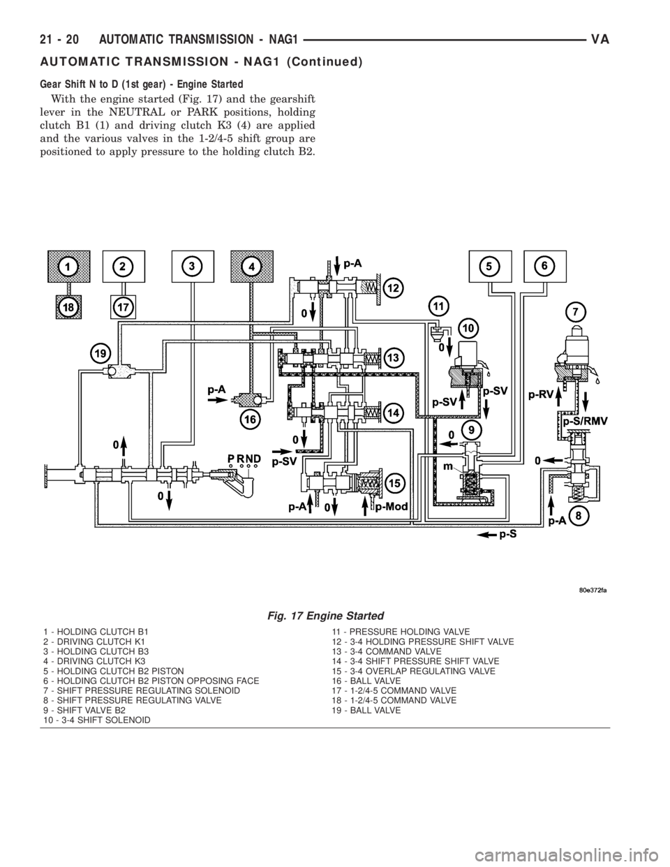
Gear Shift N to D (1st gear) - Engine Started
With the engine started (Fig. 17) and the gearshift
lever in the NEUTRAL or PARK positions, holding
clutch B1 (1) and driving clutch K3 (4) are applied
and the various valves in the 1-2/4-5 shift group are
positioned to apply pressure to the holding clutch B2.
Fig. 17 Engine Started
1 - HOLDING CLUTCH B1 11 - PRESSURE HOLDING VALVE
2 - DRIVING CLUTCH K1 12 - 3-4 HOLDING PRESSURE SHIFT VALVE
3 - HOLDING CLUTCH B3 13 - 3-4 COMMAND VALVE
4 - DRIVING CLUTCH K3 14 - 3-4 SHIFT PRESSURE SHIFT VALVE
5 - HOLDING CLUTCH B2 PISTON 15 - 3-4 OVERLAP REGULATING VALVE
6 - HOLDING CLUTCH B2 PISTON OPPOSING FACE 16 - BALL VALVE
7 - SHIFT PRESSURE REGULATING SOLENOID 17 - 1-2/4-5 COMMAND VALVE
8 - SHIFT PRESSURE REGULATING VALVE 18 - 1-2/4-5 COMMAND VALVE
9 - SHIFT VALVE B2 19 - BALL VALVE
10 - 3-4 SHIFT SOLENOID
21 - 20 AUTOMATIC TRANSMISSION - NAG1VA
AUTOMATIC TRANSMISSION - NAG1 (Continued)
Page 897 of 1232
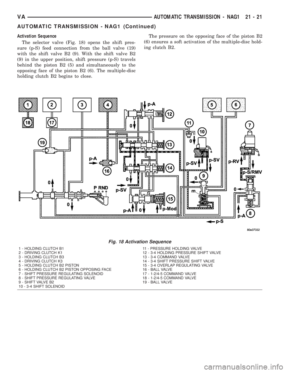
Activation Sequence
The selector valve (Fig. 18) opens the shift pres-
sure (p-S) feed connection from the ball valve (19)
with the shift valve B2 (9). With the shift valve B2
(9) in the upper position, shift pressure (p-S) travels
behind the piston B2 (5) and simultaneously to the
opposing face of the piston B2 (6). The multiple-disc
holding clutch B2 begins to close.The pressure on the opposing face of the piston B2
(6) ensures a soft activation of the multiple-disc hold-
ing clutch B2.
Fig. 18 Activation Sequence
1 - HOLDING CLUTCH B1 11 - PRESSURE HOLDING VALVE
2 - DRIVING CLUTCH K1 12 - 3-4 HOLDING PRESSURE SHIFT VALVE
3 - HOLDING CLUTCH B3 13 - 3-4 COMMAND VALVE
4 - DRIVING CLUTCH K3 14 - 3-4 SHIFT PRESSURE SHIFT VALVE
5 - HOLDING CLUTCH B2 PISTON 15 - 3-4 OVERLAP REGULATING VALVE
6 - HOLDING CLUTCH B2 PISTON OPPOSING FACE 16 - BALL VALVE
7 - SHIFT PRESSURE REGULATING SOLENOID 17 - 1-2/4-5 COMMAND VALVE
8 - SHIFT PRESSURE REGULATING VALVE 18 - 1-2/4-5 COMMAND VALVE
9 - SHIFT VALVE B2 19 - BALL VALVE
10 - 3-4 SHIFT SOLENOID
VAAUTOMATIC TRANSMISSION - NAG1 21 - 21
AUTOMATIC TRANSMISSION - NAG1 (Continued)
Page 898 of 1232
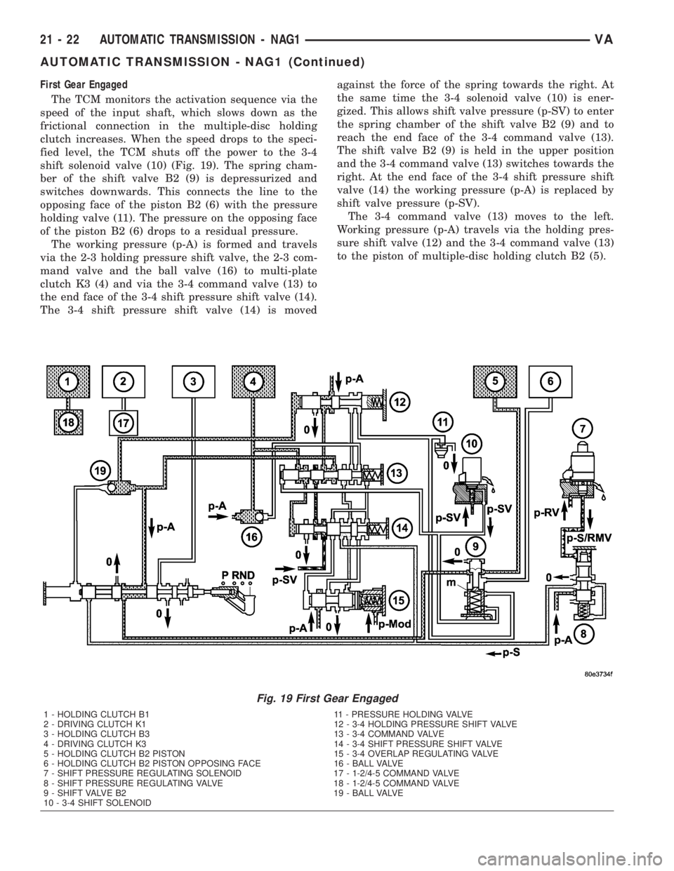
First Gear Engaged
The TCM monitors the activation sequence via the
speed of the input shaft, which slows down as the
frictional connection in the multiple-disc holding
clutch increases. When the speed drops to the speci-
fied level, the TCM shuts off the power to the 3-4
shift solenoid valve (10) (Fig. 19). The spring cham-
ber of the shift valve B2 (9) is depressurized and
switches downwards. This connects the line to the
opposing face of the piston B2 (6) with the pressure
holding valve (11). The pressure on the opposing face
of the piston B2 (6) drops to a residual pressure.
The working pressure (p-A) is formed and travels
via the 2-3 holding pressure shift valve, the 2-3 com-
mand valve and the ball valve (16) to multi-plate
clutch K3 (4) and via the 3-4 command valve (13) to
the end face of the 3-4 shift pressure shift valve (14).
The 3-4 shift pressure shift valve (14) is movedagainst the force of the spring towards the right. At
the same time the 3-4 solenoid valve (10) is ener-
gized. This allows shift valve pressure (p-SV) to enter
the spring chamber of the shift valve B2 (9) and to
reach the end face of the 3-4 command valve (13).
The shift valve B2 (9) is held in the upper position
and the 3-4 command valve (13) switches towards the
right. At the end face of the 3-4 shift pressure shift
valve (14) the working pressure (p-A) is replaced by
shift valve pressure (p-SV).
The 3-4 command valve (13) moves to the left.
Working pressure (p-A) travels via the holding pres-
sure shift valve (12) and the 3-4 command valve (13)
to the piston of multiple-disc holding clutch B2 (5).
Fig. 19 First Gear Engaged
1 - HOLDING CLUTCH B1 11 - PRESSURE HOLDING VALVE
2 - DRIVING CLUTCH K1 12 - 3-4 HOLDING PRESSURE SHIFT VALVE
3 - HOLDING CLUTCH B3 13 - 3-4 COMMAND VALVE
4 - DRIVING CLUTCH K3 14 - 3-4 SHIFT PRESSURE SHIFT VALVE
5 - HOLDING CLUTCH B2 PISTON 15 - 3-4 OVERLAP REGULATING VALVE
6 - HOLDING CLUTCH B2 PISTON OPPOSING FACE 16 - BALL VALVE
7 - SHIFT PRESSURE REGULATING SOLENOID 17 - 1-2/4-5 COMMAND VALVE
8 - SHIFT PRESSURE REGULATING VALVE 18 - 1-2/4-5 COMMAND VALVE
9 - SHIFT VALVE B2 19 - BALL VALVE
10 - 3-4 SHIFT SOLENOID
21 - 22 AUTOMATIC TRANSMISSION - NAG1VA
AUTOMATIC TRANSMISSION - NAG1 (Continued)
Page 899 of 1232
DIAGNOSIS AND TESTING
DIAGNOSIS AND TESTING - AUTOMATIC
TRANSMISSION
CAUTION: Before attempting any repair on a NAG1
automatic transmission, check for Diagnostic Trou-
ble Codes with the DRBTscan tool.
Transmission malfunctions may be caused by these
general conditions:
²Poor engine performance.
²Improper adjustments.
²Hydraulic malfunctions.
²Mechanical malfunctions.
²Electronic malfunctions.
²Transfer case performance.
Diagnosis of these problems should always begin
by checking the easily accessible variables: fluid level
and condition, gearshift cable adjustment. Then per-
form a road test to determine if the problem has been
corrected or if more diagnosis is necessary.
DIAGNOSIS AND TESTING - PRELIMINARY
Two basic procedures are required. One procedure
for vehicles that are drivable and an alternate proce-
dure for disabled vehicles (will not back up or move
forward).
VEHICLE IS DRIVABLE
(1) Check for transmission fault codes using DRBt
scan tool.
(2) Check fluid level and condition.
(3) Adjust gearshift cable if complaint was based
on delayed, erratic, or harsh shifts.
(4) Road test and note how transmission upshifts,
downshifts, and engages.
VEHICLE IS DISABLED
(1) Check fluid level and condition.(2) Check for broken or disconnected gearshift
cable.
(3) Check for cracked, leaking cooler lines, or loose
or missing pressure-port plugs.
(4) Raise and support vehicle on safety stands,
start engine, shift transmission into gear, and note
following:
(a) If propeller shaft turns but wheels do not,
problem is with differential or axle shafts.
(b) If propeller shaft does not turn and transmis-
sion is noisy, stop engine. Remove oil pan, and
check for debris. If pan is clear, remove transmis-
sion and check for damaged driveplate, converter,
oil pump, or input shaft.
(c) If propeller shaft does not turn and transmis-
sion is not noisy, perform hydraulic-pressure test to
determine if problem is hydraulic or mechanical.
DIAGNOSIS AND TESTING - ROAD TESTING
Before road testing, be sure the fluid level and con-
trol cable adjustments have been checked and
adjusted if necessary. Verify that all diagnostic trou-
ble codes have been resolved.
Observe engine performance during the road test.
A poorly tuned engine will not allow accurate analy-
sis of transmission operation.
Operate the transmission in all gear ranges. Check
for shift variations and engine flare which indicates
slippage. Note if shifts are harsh, spongy, delayed,
early, or if part throttle downshifts are sensitive.
Slippage indicated by engine flare, usually means
clutch, overrunning clutch, or line pressure problems.
A slipping clutch can often be determined by com-
paring which internal units are applied in the vari-
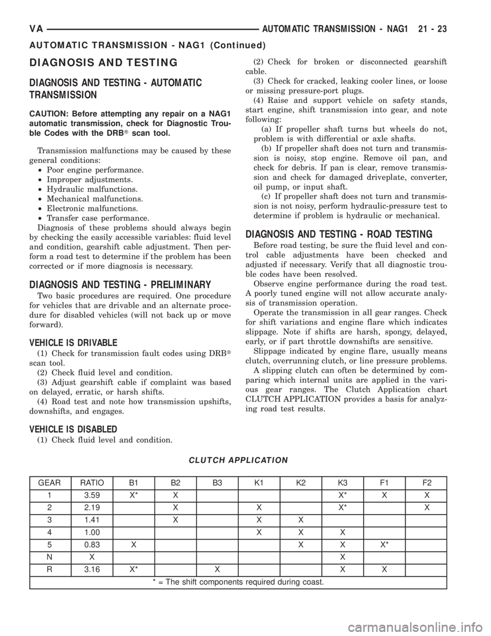
ous gear ranges. The Clutch Application chart
CLUTCH APPLICATION provides a basis for analyz-
ing road test results.
CLUTCH APPLICATION
GEAR RATIO B1 B2 B3 K1 K2 K3 F1 F2
1 3.59 X* X X* X X
2 2.19 X X X* X
3 1.41 X X X
4 1.00 X X X
5 0.83 X X X X*
NX X
R 3.16 X* X X X
* = The shift components required during coast.
VAAUTOMATIC TRANSMISSION - NAG1 21 - 23
AUTOMATIC TRANSMISSION - NAG1 (Continued)
Page 900 of 1232
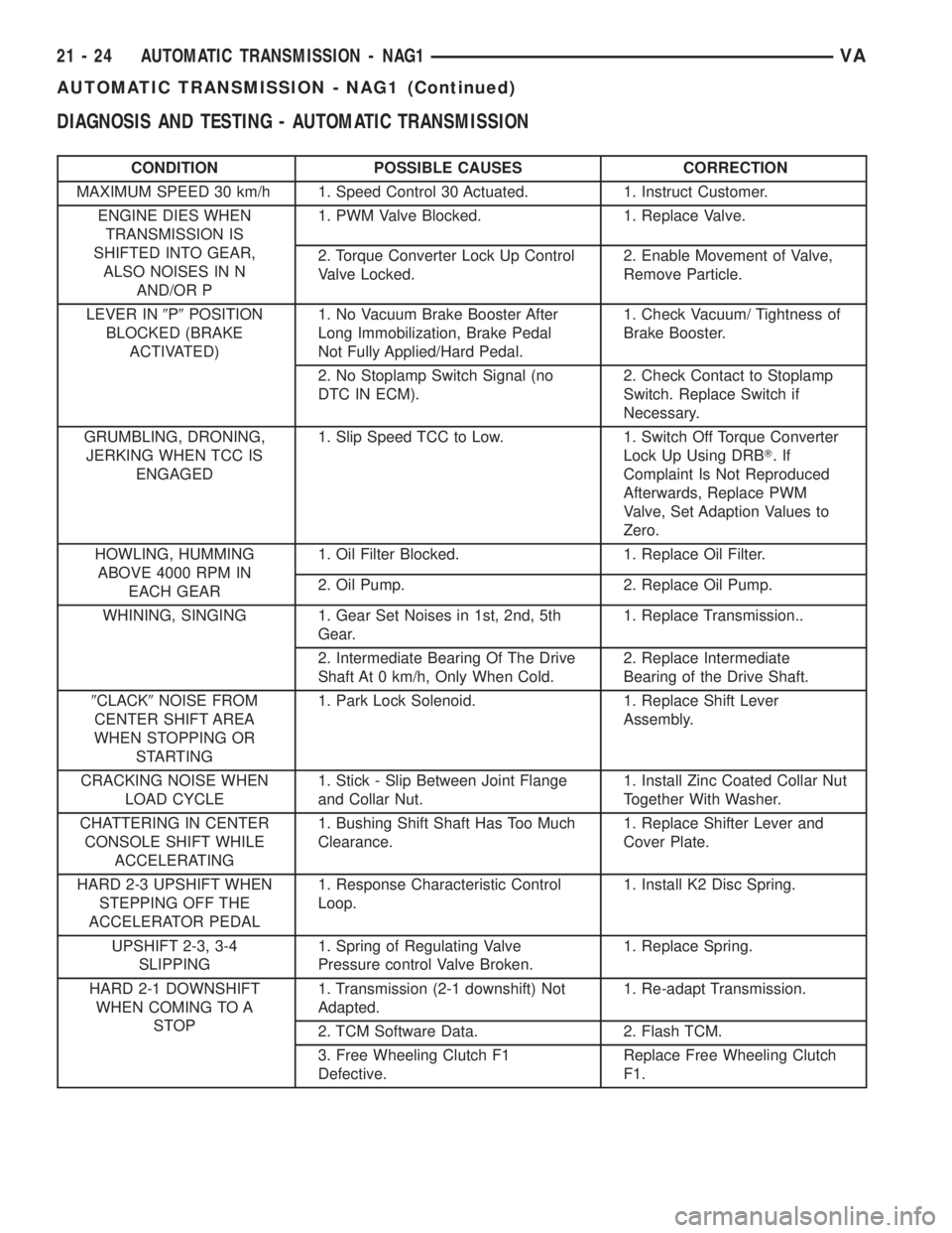
DIAGNOSIS AND TESTING - AUTOMATIC TRANSMISSION
CONDITION POSSIBLE CAUSES CORRECTION
MAXIMUM SPEED 30 km/h 1. Speed Control 30 Actuated. 1. Instruct Customer.
ENGINE DIES WHEN
TRANSMISSION IS
SHIFTED INTO GEAR,
ALSO NOISES IN N
AND/OR P1. PWM Valve Blocked. 1. Replace Valve.
2. Torque Converter Lock Up Control
Valve Locked.2. Enable Movement of Valve,
Remove Particle.
LEVER IN9P9POSITION
BLOCKED (BRAKE
ACTIVATED)1. No Vacuum Brake Booster After
Long Immobilization, Brake Pedal
Not Fully Applied/Hard Pedal.1. Check Vacuum/ Tightness of
Brake Booster.
2. No Stoplamp Switch Signal (no
DTC IN ECM).2. Check Contact to Stoplamp
Switch. Replace Switch if
Necessary.
GRUMBLING, DRONING,
JERKING WHEN TCC IS
ENGAGED1. Slip Speed TCC to Low. 1. Switch Off Torque Converter
Lock Up Using DRBT.If
Complaint Is Not Reproduced
Afterwards, Replace PWM
Valve, Set Adaption Values to
Zero.
HOWLING, HUMMING
ABOVE 4000 RPM IN
EACH GEAR1. Oil Filter Blocked. 1. Replace Oil Filter.
2. Oil Pump. 2. Replace Oil Pump.
WHINING, SINGING 1. Gear Set Noises in 1st, 2nd, 5th
Gear.1. Replace Transmission..
2. Intermediate Bearing Of The Drive
Shaft At 0 km/h, Only When Cold.2. Replace Intermediate
Bearing of the Drive Shaft.
9CLACK9NOISE FROM
CENTER SHIFT AREA
WHEN STOPPING OR
STARTING1. Park Lock Solenoid. 1. Replace Shift Lever
Assembly.
CRACKING NOISE WHEN
LOAD CYCLE1. Stick - Slip Between Joint Flange
and Collar Nut.1. Install Zinc Coated Collar Nut
Together With Washer.
CHATTERING IN CENTER
CONSOLE SHIFT WHILE
ACCELERATING1. Bushing Shift Shaft Has Too Much
Clearance.1. Replace Shifter Lever and
Cover Plate.
HARD 2-3 UPSHIFT WHEN
STEPPING OFF THE
ACCELERATOR PEDAL1. Response Characteristic Control
Loop.1. Install K2 Disc Spring.
UPSHIFT 2-3, 3-4
SLIPPING1. Spring of Regulating Valve
Pressure control Valve Broken.1. Replace Spring.
HARD 2-1 DOWNSHIFT
WHEN COMING TO A
STOP1. Transmission (2-1 downshift) Not
Adapted.1. Re-adapt Transmission.
2. TCM Software Data. 2. Flash TCM.
3. Free Wheeling Clutch F1
Defective.Replace Free Wheeling Clutch
F1.
21 - 24 AUTOMATIC TRANSMISSION - NAG1VA
AUTOMATIC TRANSMISSION - NAG1 (Continued)