MERCEDES-BENZ SPRINTER 2006 Service Manual
Manufacturer: MERCEDES-BENZ, Model Year: 2006, Model line: SPRINTER, Model: MERCEDES-BENZ SPRINTER 2006Pages: 2305, PDF Size: 48.12 MB
Page 2131 of 2305
(8) Charge the rear refrigerant system (Refer to 24
- HEATING & AIR CONDITIONING/PLUMBING -
STANDARD PROCEDURE - REFRIGERANT SYS-
TEM CHARGE).
(9) Install the cover onto the rear A/C evaporator
housing (Refer to 24 - HEATING & AIR CONDI-
TIONING/DISTRIBUTION - REAR/A/C EVAPORA-
TOR COVER-REAR - INSTALLATION).
(10) Install the cover onto the rear A/C condenser
housing (Refer to 24 - HEATING & AIR CONDI-
TIONING/DISTRIBUTION - REAR/A/C CON-
DENSER COVER - INSTALLATION).
REAR RECEIVER / DRIER
REMOVAL
WARNING: Refer to the applicable warnings and
cautions for this system before performing the fol-
lowing operation (Refer to 24 - HEATING & AIR
CONDITIONING/PLUMBING - WARNINGS) and (Refer
to 24 - HEATING & AIR CONDITIONING/PLUMBING -
CAUTIONS). Failure to follow the warnings and cau-
tions could result in possible personal injury or
death.
(1) Disconnect and isolate the negative battery
cable.
(2) Remove the air filter from the rear A/C evapo-
rator housing (Refer to 24 - HEATING & AIR CON-
DITIONING/DISTRIBUTION - REAR/AIR FILTER -
REMOVAL).
(3) Recover the refrigerant from the rear refriger-
ant system (Refer to 24 - HEATING & AIR CONDI-
TIONING/PLUMBING - STANDARD PROCEDURE -
REFRIGERANT RECOVERY).
(4) Remove the cover from the rear A/C condenser
housing (Refer to 24 - HEATING & AIR CONDI-
TIONING/DISTRIBUTION - REAR/A/C CON-
DENSER COVER - REMOVAL).
(5) Disconnect the rear refrigerant reservoir from
the rear receiver/drier and remove and discard the
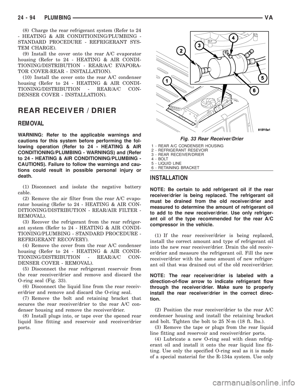
O-ring seal (Fig. 33).
(6) Disconnect the liquid line from the rear receiv-
er/drier and remove and discard the O-ring seal.
(7) Remove the bolt and retaining bracket that
secures the rear receiver/drier to the rear A/C con-
denser housing and remove the receiver/drier.
(8) Install plugs into, or tape over the opened rear
liquid line fitting and reservoir and receiver/drier
ports.
INSTALLATION
NOTE: Be certain to add refrigerant oil if the rear
receiver/drier is being replaced. The refrigerant oil
must be drained from the old receiver/drier and
measured to determine the amount of refrigerant oil
to add to the new receiver/drier. Use only refriger-
ant oil of the type recommended for the rear A/C
compressor in the vehicle.
(1) If the rear receiver/drier is being replaced,
install the correct amount and type of refrigerant oil
into the new rear receiver/drier. Drain the old receiv-
er/drier and measure the refrigerant oil. Fill the new
receiver/drier with the same amount of new refriger-
ant oil that was drained out of the old receiver/drier.
NOTE: The rear receiver/drier is labeled with a
direction-of-flow arrow to indicate refrigerant flow
through the receiver/drier. Make sure to properly
install the rear receiver/drier in the correct direc-
tion.
(2) Position the rear receiver/drier to the rear A/C
condenser housing and install the retaining bracket
and bolt. Tighten the bolt to 25 N´m (18 ft. lbs.).
(3) Remove the tape or plugs from the rear liquid
line fitting and reservoir and receiver/drier ports.
(4) Lubricate a new O-ring seal with clean refrig-
erant oil and install it onto the rear liquid line fit-
ting. Use only the specified O-ring seal as it is made
of a special material for the R-134a system. Use only
Fig. 33 Rear Receiver/Drier
1 - REAR A/C CONDENSER HOUSING
2 - REFRIGERANT RESEVOIR
3 - REAR RECEIVER/DRIER
4 - BOLT
5 - LIQUID LINE
6 - RETAINING BRACKET
24 - 94 PLUMBINGVA
Page 2132 of 2305
refrigerant oil of the type recommended for the rear
A/C compressor in the vehicle.
(5) Connect the rear liquid line to the rear receiv-
er/drier. Tighten the nut to 35 N´m (26 ft. lbs.).
(6) Lubricate a new O-ring seal with clean refrig-
erant oil and install it onto the receiver/drier outlet
fitting. Use only the specified O-ring seal as it is
made of a special material for the R-134a system.
Use only refrigerant oil of the type recommended for
the rear A/C compressor in the vehicle.
(7) Connect the rear refrigerant reservoir to the
rear receiver/drier. Tighten the nut to 35 N´m (26 ft.
lbs.).
(8) Reconnect the negative battery cable.
(9) Evacuate the rear refrigerant system (Refer to
24 - HEATING & AIR CONDITIONING/PLUMBING
- STANDARD PROCEDURE - REFRIGERANT SYS-
TEM EVACUATE).
(10) Charge the rear refrigerant system (Refer to
24 - HEATING & AIR CONDITIONING/PLUMBING
- STANDARD PROCEDURE - REFRIGERANT SYS-
TEM CHARGE).
(11) Install the rear air filter (Refer to 24 - HEAT-
ING & AIR CONDITIONING/DISTRIBUTION -
REAR/AIR FILTER - INSTALLATION).
(12) Install the cover onto the rear A/C condenser
housing (Refer to 24 - HEATING & AIR CONDI-
TIONING/DISTRIBUTION - REAR/A/C CON-
DENSER COVER - INSTALLATION).
REAR REFRIGERANT RESER-
VOIR
REMOVAL
WARNING: Refer to the applicable warnings and
cautions for this system before performing the fol-
lowing operation (Refer to 24 - HEATING & AIR
CONDITIONING/PLUMBING - WARNINGS) and (Refer
to 24 - HEATING & AIR CONDITIONING/PLUMBING -
CAUTIONS). Failure to follow the warnings and cau-
tions could result in possible personal injury or
death.
(1) Disconnect and isolate the negative battery
cable.
(2) Remove the air filter from the rear A/C evapo-
rator housing (Refer to 24 - HEATING & AIR CON-
DITIONING/DISTRIBUTION - REAR/AIR FILTER -
REMOVAL).
(3) Recover the refrigerant from the rear refriger-
ant system (Refer to 24 - HEATING & AIR CONDI-
TIONING/PLUMBING - STANDARD PROCEDURE -
REFRIGERANT RECOVERY).
(4) Remove the cover from the rear A/C condenser
housing (Refer to 24 - HEATING & AIR CONDI-TIONING/DISTRIBUTION - REAR/A/C CON-
DENSER COVER - REMOVAL).
(5) Disconnect the rear liquid line from the rear
refrigerant reservoir and remove and discard the
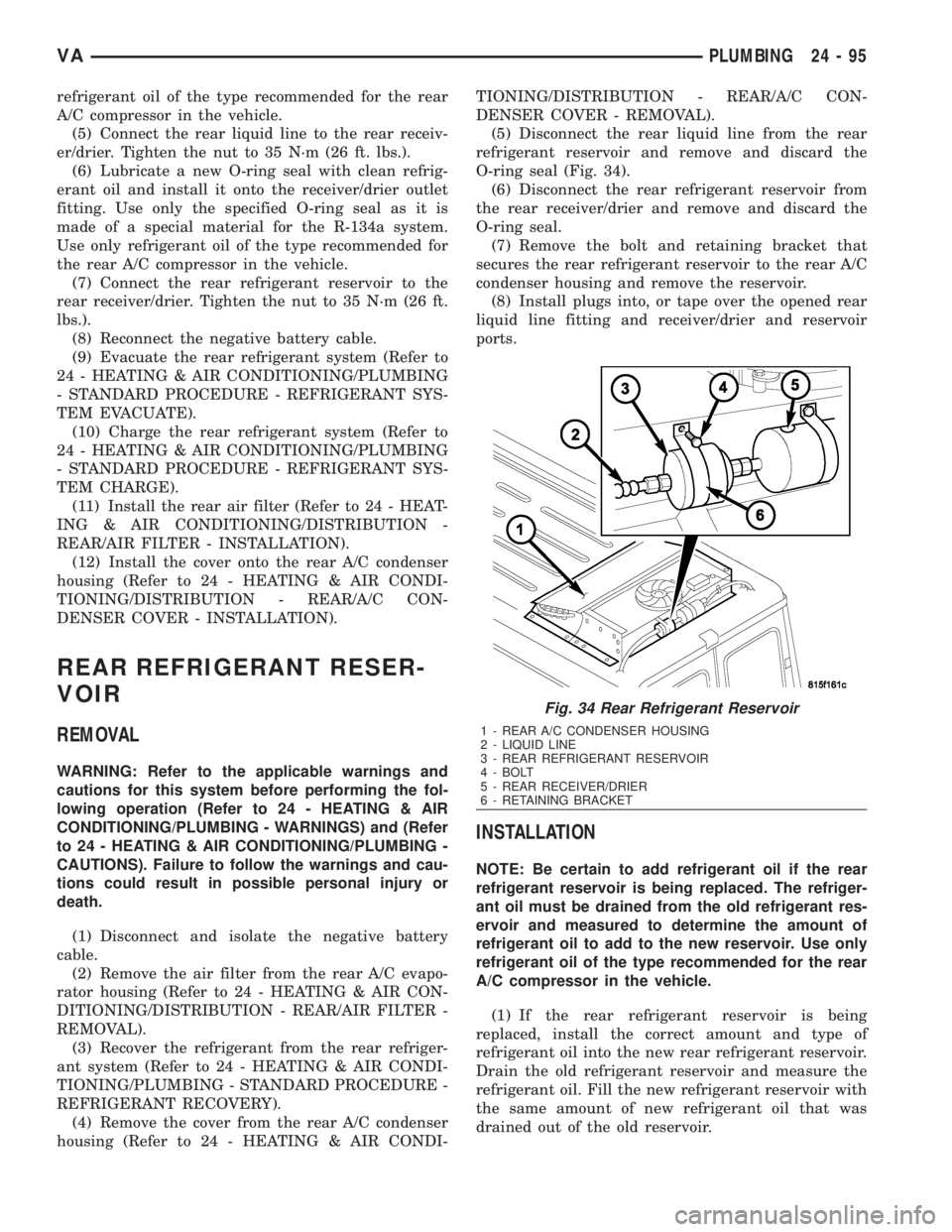
O-ring seal (Fig. 34).
(6) Disconnect the rear refrigerant reservoir from
the rear receiver/drier and remove and discard the
O-ring seal.
(7) Remove the bolt and retaining bracket that
secures the rear refrigerant reservoir to the rear A/C
condenser housing and remove the reservoir.
(8) Install plugs into, or tape over the opened rear
liquid line fitting and receiver/drier and reservoir
ports.
INSTALLATION
NOTE: Be certain to add refrigerant oil if the rear
refrigerant reservoir is being replaced. The refriger-
ant oil must be drained from the old refrigerant res-
ervoir and measured to determine the amount of
refrigerant oil to add to the new reservoir. Use only
refrigerant oil of the type recommended for the rear
A/C compressor in the vehicle.
(1) If the rear refrigerant reservoir is being
replaced, install the correct amount and type of
refrigerant oil into the new rear refrigerant reservoir.
Drain the old refrigerant reservoir and measure the
refrigerant oil. Fill the new refrigerant reservoir with
the same amount of new refrigerant oil that was
drained out of the old reservoir.
Fig. 34 Rear Refrigerant Reservoir
1 - REAR A/C CONDENSER HOUSING
2 - LIQUID LINE
3 - REAR REFRIGERANT RESERVOIR
4 - BOLT
5 - REAR RECEIVER/DRIER
6 - RETAINING BRACKET
VAPLUMBING 24 - 95
Page 2133 of 2305
(2) Install a new rear receiver/drier (Refer to 24 -
HEATING & AIR CONDITIONING/PLUMBING/
REAR RECEIVER/DRIER - INSTALLATION).
(3) Position the rear refrigerant reservoir to the
rear A/C condenser housing and install the retaining
bracket and bolt. Tighten the bolt to 25 N´m (18 ft.
lbs.).
(4) Remove the tape or plugs from the rear liquid
line fitting and receiver/drier and reservoir ports.
(5) Lubricate a new O-ring seal with clean refrig-
erant oil and install it onto the rear receiver/drier fit-
ting. Use only the specified O-ring seal as it is made
of a special material for the R-134a system. Use only
refrigerant oil of the type recommended for the rear
A/C compressor in the vehicle.
(6) Connect the rear receiver/drier to the rear
refrigerant reservoir. Tighten the nut to 35 N´m (26
ft. lbs.).
(7) Lubricate a new O-ring seal with clean refrig-
erant oil and install it onto the rear liquid line fit-
ting. Use only the specified O-ring seal as it is made
of a special material for the R-134a system. Use only
refrigerant oil of the type recommended for the rear
A/C compressor in the vehicle.
(8) Connect the rear liquid line to the rear refrig-
erant reservoir. Tighten the nut to 35 N´m (26 ft.
lbs.).
(9) Reconnect the negative battery cable.
(10) Evacuate the rear refrigerant system (Refer to
24 - HEATING & AIR CONDITIONING/PLUMBING
- STANDARD PROCEDURE - REFRIGERANT SYS-
TEM EVACUATE).
(11) Charge the rear refrigerant system (Refer to
24 - HEATING & AIR CONDITIONING/PLUMBING
- STANDARD PROCEDURE - REFRIGERANT SYS-
TEM CHARGE).
(12) Install the rear air filter (Refer to 24 - HEAT-
ING & AIR CONDITIONING/DISTRIBUTION -
REAR/AIR FILTER - INSTALLATION).
(13) Install the cover onto the rear A/C condenser
housing (Refer to 24 - HEATING & AIR CONDI-
TIONING/DISTRIBUTION - REAR/A/C CON-
DENSER COVER - INSTALLATION).
REAR SUCTION LINE
DESCRIPTION
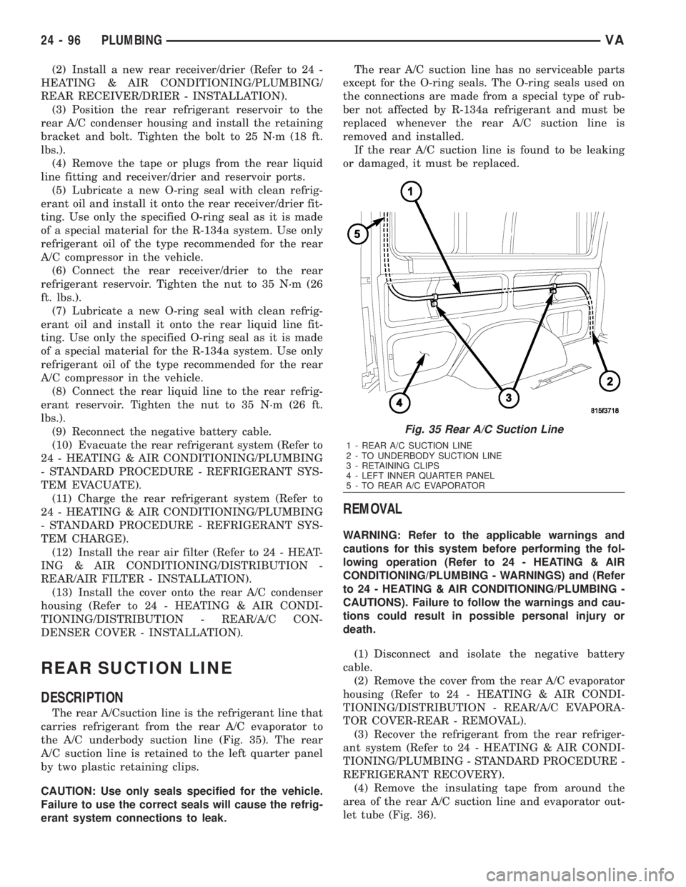
The rear A/Csuction line is the refrigerant line that
carries refrigerant from the rear A/C evaporator to
the A/C underbody suction line (Fig. 35). The rear
A/C suction line is retained to the left quarter panel
by two plastic retaining clips.
CAUTION: Use only seals specified for the vehicle.
Failure to use the correct seals will cause the refrig-
erant system connections to leak.The rear A/C suction line has no serviceable parts
except for the O-ring seals. The O-ring seals used on
the connections are made from a special type of rub-
ber not affected by R-134a refrigerant and must be
replaced whenever the rear A/C suction line is
removed and installed.
If the rear A/C suction line is found to be leaking
or damaged, it must be replaced.
REMOVAL
WARNING: Refer to the applicable warnings and
cautions for this system before performing the fol-
lowing operation (Refer to 24 - HEATING & AIR
CONDITIONING/PLUMBING - WARNINGS) and (Refer
to 24 - HEATING & AIR CONDITIONING/PLUMBING -
CAUTIONS). Failure to follow the warnings and cau-
tions could result in possible personal injury or
death.
(1) Disconnect and isolate the negative battery
cable.
(2) Remove the cover from the rear A/C evaporator
housing (Refer to 24 - HEATING & AIR CONDI-
TIONING/DISTRIBUTION - REAR/A/C EVAPORA-
TOR COVER-REAR - REMOVAL).
(3) Recover the refrigerant from the rear refriger-
ant system (Refer to 24 - HEATING & AIR CONDI-
TIONING/PLUMBING - STANDARD PROCEDURE -
REFRIGERANT RECOVERY).
(4) Remove the insulating tape from around the
area of the rear A/C suction line and evaporator out-
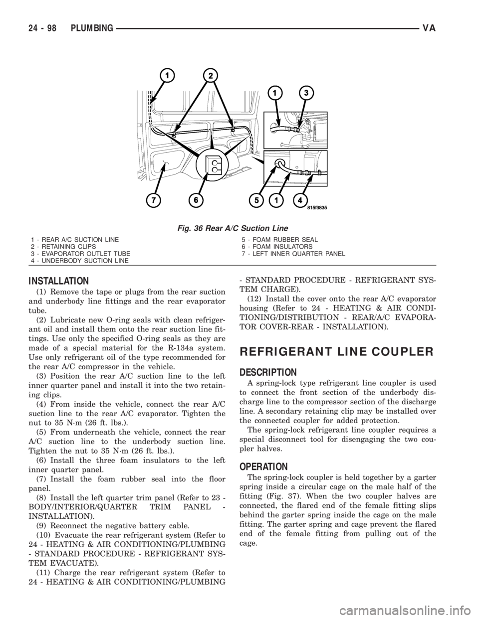
let tube (Fig. 36).
Fig. 35 Rear A/C Suction Line
1 - REAR A/C SUCTION LINE
2 - TO UNDERBODY SUCTION LINE
3 - RETAINING CLIPS
4 - LEFT INNER QUARTER PANEL
5 - TO REAR A/C EVAPORATOR
24 - 96 PLUMBINGVA
Page 2134 of 2305
(5) From inside the vehicle, disconnect the rear
A/C suction line from the rear A/C evaporator and
remove and discard the O-ring seal.
(6) From underneath the vehicle, disconnect the
rear A/C suction line from the underbody suction line
and remove and discard the O-ring seal.
(7) Remove the left quarter trim panel (Refer to 23
- BODY/INTERIOR/QUARTER TRIM PANEL -
REMOVAL).
(8) Remove the three foam insulators from the left
inner quarter panel.
(9) Remove the foam rubber seal from the opening
in the floor of the cargo compartment.
(10) Disengage the rear A/C suction line from the
two retaining clips located on the inner quarter panel
and remove the suction line.
(11) Install plugs into, or tape over the opened
rear suction and underbody line fittings and evapora-
tor tube.
VAPLUMBING 24 - 97
Page 2135 of 2305
INSTALLATION
(1) Remove the tape or plugs from the rear suction
and underbody line fittings and the rear evaporator
tube.
(2) Lubricate new O-ring seals with clean refriger-
ant oil and install them onto the rear suction line fit-
tings. Use only the specified O-ring seals as they are
made of a special material for the R-134a system.
Use only refrigerant oil of the type recommended for
the rear A/C compressor in the vehicle.
(3) Position the rear A/C suction line to the left
inner quarter panel and install it into the two retain-
ing clips.
(4) From inside the vehicle, connect the rear A/C
suction line to the rear A/C evaporator. Tighten the
nut to 35 N´m (26 ft. lbs.).
(5) From underneath the vehicle, connect the rear
A/C suction line to the underbody suction line.
Tighten the nut to 35 N´m (26 ft. lbs.).
(6) Install the three foam insulators to the left
inner quarter panel.
(7) Install the foam rubber seal into the floor
panel.
(8) Install the left quarter trim panel (Refer to 23 -
BODY/INTERIOR/QUARTER TRIM PANEL -
INSTALLATION).
(9) Reconnect the negative battery cable.
(10) Evacuate the rear refrigerant system (Refer to
24 - HEATING & AIR CONDITIONING/PLUMBING
- STANDARD PROCEDURE - REFRIGERANT SYS-
TEM EVACUATE).
(11) Charge the rear refrigerant system (Refer to
24 - HEATING & AIR CONDITIONING/PLUMBING- STANDARD PROCEDURE - REFRIGERANT SYS-
TEM CHARGE).
(12) Install the cover onto the rear A/C evaporator
housing (Refer to 24 - HEATING & AIR CONDI-
TIONING/DISTRIBUTION - REAR/A/C EVAPORA-
TOR COVER-REAR - INSTALLATION).
REFRIGERANT LINE COUPLER
DESCRIPTION
A spring-lock type refrigerant line coupler is used
to connect the front section of the underbody dis-
charge line to the compressor section of the discharge
line. A secondary retaining clip may be installed over
the connected coupler for added protection.
The spring-lock refrigerant line coupler requires a
special disconnect tool for disengaging the two cou-
pler halves.
OPERATION
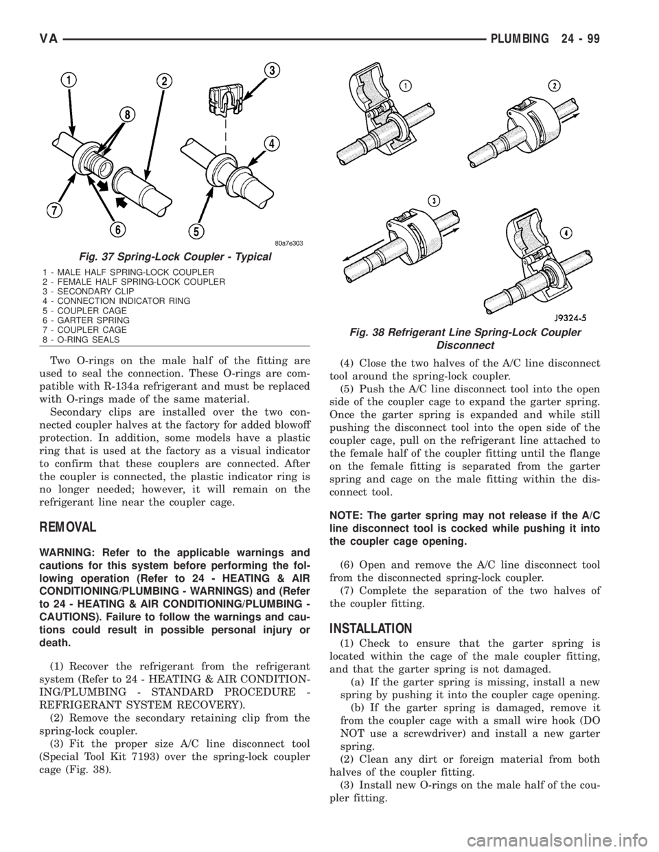
The spring-lock coupler is held together by a garter
spring inside a circular cage on the male half of the
fitting (Fig. 37). When the two coupler halves are
connected, the flared end of the female fitting slips
behind the garter spring inside the cage on the male
fitting. The garter spring and cage prevent the flared
end of the female fitting from pulling out of the
cage.
Fig. 36 Rear A/C Suction Line
1 - REAR A/C SUCTION LINE
2 - RETAINING CLIPS
3 - EVAPORATOR OUTLET TUBE
4 - UNDERBODY SUCTION LINE5 - FOAM RUBBER SEAL
6 - FOAM INSULATORS
7 - LEFT INNER QUARTER PANEL
24 - 98 PLUMBINGVA
Page 2136 of 2305
Two O-rings on the male half of the fitting are
used to seal the connection. These O-rings are com-
patible with R-134a refrigerant and must be replaced
with O-rings made of the same material.
Secondary clips are installed over the two con-
nected coupler halves at the factory for added blowoff
protection. In addition, some models have a plastic
ring that is used at the factory as a visual indicator
to confirm that these couplers are connected. After
the coupler is connected, the plastic indicator ring is
no longer needed; however, it will remain on the
refrigerant line near the coupler cage.
REMOVAL
WARNING: Refer to the applicable warnings and
cautions for this system before performing the fol-
lowing operation (Refer to 24 - HEATING & AIR
CONDITIONING/PLUMBING - WARNINGS) and (Refer
to 24 - HEATING & AIR CONDITIONING/PLUMBING -
CAUTIONS). Failure to follow the warnings and cau-
tions could result in possible personal injury or
death.
(1) Recover the refrigerant from the refrigerant
system (Refer to 24 - HEATING & AIR CONDITION-
ING/PLUMBING - STANDARD PROCEDURE -
REFRIGERANT SYSTEM RECOVERY).
(2) Remove the secondary retaining clip from the
spring-lock coupler.
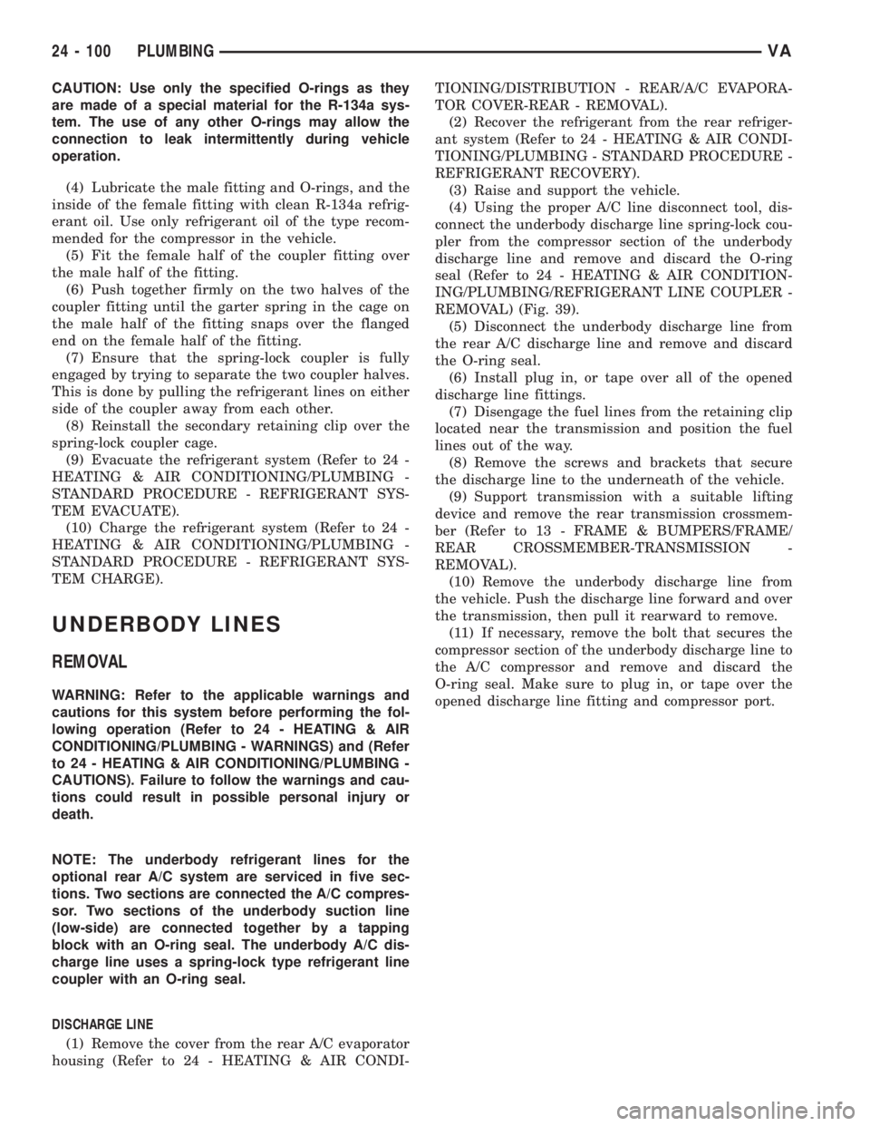
(3) Fit the proper size A/C line disconnect tool
(Special Tool Kit 7193) over the spring-lock coupler
cage (Fig. 38).(4) Close the two halves of the A/C line disconnect
tool around the spring-lock coupler.
(5) Push the A/C line disconnect tool into the open
side of the coupler cage to expand the garter spring.
Once the garter spring is expanded and while still
pushing the disconnect tool into the open side of the
coupler cage, pull on the refrigerant line attached to
the female half of the coupler fitting until the flange
on the female fitting is separated from the garter
spring and cage on the male fitting within the dis-
connect tool.
NOTE: The garter spring may not release if the A/C
line disconnect tool is cocked while pushing it into
the coupler cage opening.
(6) Open and remove the A/C line disconnect tool
from the disconnected spring-lock coupler.
(7) Complete the separation of the two halves of
the coupler fitting.
INSTALLATION
(1) Check to ensure that the garter spring is
located within the cage of the male coupler fitting,
and that the garter spring is not damaged.
(a) If the garter spring is missing, install a new
spring by pushing it into the coupler cage opening.
(b) If the garter spring is damaged, remove it
from the coupler cage with a small wire hook (DO
NOT use a screwdriver) and install a new garter
spring.
(2) Clean any dirt or foreign material from both
halves of the coupler fitting.
(3) Install new O-rings on the male half of the cou-
pler fitting.
Fig. 37 Spring-Lock Coupler - Typical
1 - MALE HALF SPRING-LOCK COUPLER
2 - FEMALE HALF SPRING-LOCK COUPLER
3 - SECONDARY CLIP
4 - CONNECTION INDICATOR RING
5 - COUPLER CAGE
6 - GARTER SPRING
7 - COUPLER CAGE
8 - O-RING SEALS
Fig. 38 Refrigerant Line Spring-Lock Coupler
Disconnect
VAPLUMBING 24 - 99
Page 2137 of 2305
CAUTION: Use only the specified O-rings as they
are made of a special material for the R-134a sys-
tem. The use of any other O-rings may allow the
connection to leak intermittently during vehicle
operation.
(4) Lubricate the male fitting and O-rings, and the
inside of the female fitting with clean R-134a refrig-
erant oil. Use only refrigerant oil of the type recom-
mended for the compressor in the vehicle.
(5) Fit the female half of the coupler fitting over
the male half of the fitting.
(6) Push together firmly on the two halves of the
coupler fitting until the garter spring in the cage on
the male half of the fitting snaps over the flanged
end on the female half of the fitting.
(7) Ensure that the spring-lock coupler is fully
engaged by trying to separate the two coupler halves.
This is done by pulling the refrigerant lines on either
side of the coupler away from each other.
(8) Reinstall the secondary retaining clip over the
spring-lock coupler cage.
(9) Evacuate the refrigerant system (Refer to 24 -
HEATING & AIR CONDITIONING/PLUMBING -
STANDARD PROCEDURE - REFRIGERANT SYS-
TEM EVACUATE).
(10) Charge the refrigerant system (Refer to 24 -
HEATING & AIR CONDITIONING/PLUMBING -
STANDARD PROCEDURE - REFRIGERANT SYS-
TEM CHARGE).
UNDERBODY LINES
REMOVAL
WARNING: Refer to the applicable warnings and
cautions for this system before performing the fol-
lowing operation (Refer to 24 - HEATING & AIR
CONDITIONING/PLUMBING - WARNINGS) and (Refer
to 24 - HEATING & AIR CONDITIONING/PLUMBING -
CAUTIONS). Failure to follow the warnings and cau-
tions could result in possible personal injury or
death.
NOTE: The underbody refrigerant lines for the
optional rear A/C system are serviced in five sec-
tions. Two sections are connected the A/C compres-
sor. Two sections of the underbody suction line
(low-side) are connected together by a tapping
block with an O-ring seal. The underbody A/C dis-
charge line uses a spring-lock type refrigerant line
coupler with an O-ring seal.
DISCHARGE LINE
(1) Remove the cover from the rear A/C evaporator
housing (Refer to 24 - HEATING & AIR CONDI-TIONING/DISTRIBUTION - REAR/A/C EVAPORA-
TOR COVER-REAR - REMOVAL).
(2) Recover the refrigerant from the rear refriger-
ant system (Refer to 24 - HEATING & AIR CONDI-
TIONING/PLUMBING - STANDARD PROCEDURE -
REFRIGERANT RECOVERY).
(3) Raise and support the vehicle.
(4) Using the proper A/C line disconnect tool, dis-
connect the underbody discharge line spring-lock cou-
pler from the compressor section of the underbody
discharge line and remove and discard the O-ring
seal (Refer to 24 - HEATING & AIR CONDITION-
ING/PLUMBING/REFRIGERANT LINE COUPLER -
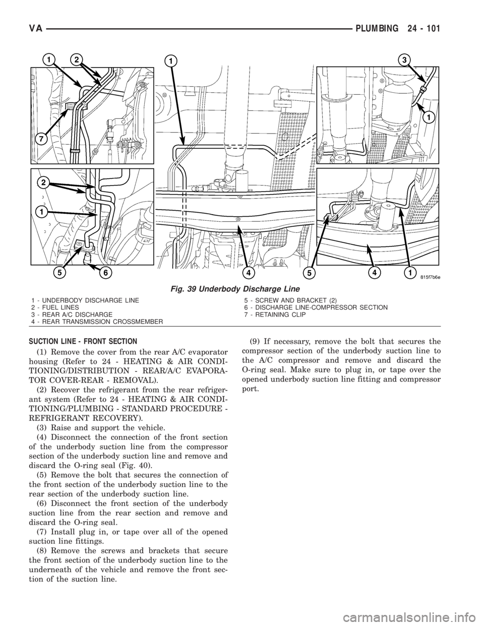
REMOVAL) (Fig. 39).
(5) Disconnect the underbody discharge line from
the rear A/C discharge line and remove and discard
the O-ring seal.
(6) Install plug in, or tape over all of the opened
discharge line fittings.
(7) Disengage the fuel lines from the retaining clip
located near the transmission and position the fuel
lines out of the way.
(8) Remove the screws and brackets that secure
the discharge line to the underneath of the vehicle.
(9) Support transmission with a suitable lifting
device and remove the rear transmission crossmem-
ber (Refer to 13 - FRAME & BUMPERS/FRAME/
REAR CROSSMEMBER-TRANSMISSION -
REMOVAL).
(10) Remove the underbody discharge line from
the vehicle. Push the discharge line forward and over
the transmission, then pull it rearward to remove.
(11) If necessary, remove the bolt that secures the
compressor section of the underbody discharge line to
the A/C compressor and remove and discard the
O-ring seal. Make sure to plug in, or tape over the
opened discharge line fitting and compressor port.
24 - 100 PLUMBINGVA
Page 2138 of 2305
SUCTION LINE - FRONT SECTION
(1) Remove the cover from the rear A/C evaporator
housing (Refer to 24 - HEATING & AIR CONDI-
TIONING/DISTRIBUTION - REAR/A/C EVAPORA-
TOR COVER-REAR - REMOVAL).
(2) Recover the refrigerant from the rear refriger-
ant system (Refer to 24 - HEATING & AIR CONDI-
TIONING/PLUMBING - STANDARD PROCEDURE -
REFRIGERANT RECOVERY).
(3) Raise and support the vehicle.
(4) Disconnect the connection of the front section
of the underbody suction line from the compressor
section of the underbody suction line and remove and
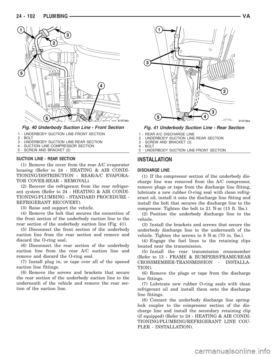
discard the O-ring seal (Fig. 40).
(5) Remove the bolt that secures the connection of
the front section of the underbody suction line to the
rear section of the underbody suction line.
(6) Disconnect the front section of the underbody
suction line from the rear section and remove and
discard the O-ring seal.
(7) Install plug in, or tape over all of the opened
suction line fittings.
(8) Remove the screws and brackets that secure
the front section of the underbody suction line to the
underneath of the vehicle and remove the front sec-
tion of the suction line.(9) If necessary, remove the bolt that secures the
compressor section of the underbody suction line to
the A/C compressor and remove and discard the
O-ring seal. Make sure to plug in, or tape over the
opened underbody suction line fitting and compressor
port.
Fig. 39 Underbody Discharge Line
1 - UNDERBODY DISCHARGE LINE
2 - FUEL LINES
3 - REAR A/C DISCHARGE
4 - REAR TRANSMISSION CROSSMEMBER5 - SCREW AND BRACKET (2)
6 - DISCHARGE LINE-COMPRESSOR SECTION
7 - RETAINING CLIP
VAPLUMBING 24 - 101
Page 2139 of 2305
SUCTION LINE - REAR SECTION
(1) Remove the cover from the rear A/C evaporator
housing (Refer to 24 - HEATING & AIR CONDI-
TIONING/DISTRIBUTION - REAR/A/C EVAPORA-
TOR COVER-REAR - REMOVAL).
(2) Recover the refrigerant from the rear refriger-
ant system (Refer to 24 - HEATING & AIR CONDI-
TIONING/PLUMBING - STANDARD PROCEDURE -
REFRIGERANT RECOVERY).
(3) Raise and support the vehicle.
(4) Remove the bolt that secures the connection of
the front section of the underbody suction line to the
rear section of the underbody suction line (Fig. 41).
(5) Disconnect the front section of the underbody
suction line from the rear section and remove and
discard the O-ring seal.
(6) Disconnect the rear section of the underbody
suction line from the rear A/C suction line and
remove and discard the O-ring seal.
(7) Install plug in, or tape over all of the opened
suction line fittings.
(8) Remove the screws and brackets that secure
the rear section of the underbody suction line to the
underneath of the vehicle and remove the rear sec-
tion of the suction line.INSTALLATION
DISCHARGE LINE
(1) If the compressor section of the underbody dis-
charge line was removed from the A/C compressor,
remove plugs or tape from the discharge line fitting,
lubricate a new rubber O-ring seal with clean refrig-
erant oil, install it onto the discharge line fitting and
install the bolt that secures the discharge line to the
compressor. Tighten the bolt to 21 N´m (15 ft. lbs.).
(2) Position the underbody discharge line to the
vehicle.
(3) Install the brackets and screws that secure the
underbody discharge line to the underneath of the
vehicle. Tighten the screws to 8 N´m (70 in. lbs.).
(4) Engage the fuel lines to the retaining clips
located near the transmission.
(5) Install the rear transmission crossmember
(Refer to 13 - FRAME & BUMPERS/FRAME/REAR
CROSSMEMBER-TRANSMISSION - INSTALLA-
TION).
(6) Remove the plugs or tape from the discharge
line fittings.
(7) Lubricate new rubber O-ring seals with clean
refrigerant oil and install them onto the discharge
line fittings.
(8) Connect the underbody discharge line spring-
lock coupler to the compressor section of the dis-
charge line and install the secondary retaining clip
(if equipped) (Refer to 24 - HEATING & AIR CONDI-
TIONING/PLUMBING/REFRIGERANT LINE COU-
PLER - INSTALLATION).
Fig. 40 Underbody Suction Line - Front Section
1 - UNDERBODY SUCTION LINE-FRONT SECTION
2 - BOLT
3 - UNDERBODY SUCTION LINE-REAR SECTION
4 - SUCTION LINE-COMPRESSOR SECTION
5 - SCREW AND BRACKET (2)
Fig. 41 Underbody Suction Line - Rear Section
1 - REAR A/C DISCHARGE LINE
2 - UNDERBODY SUCTION LINE-REAR SECTION
3 - SCREW AND BRACKET (3)
4 - BOLT
5 - UNDERBODY SUCTION LINE-FRONT SECTION
24 - 102 PLUMBINGVA
Page 2140 of 2305
(9) Connect the rear A/C discharge line to the
underbody discharge line. Tighten the nut to 35 N´m
(26 ft. lbs.).
(10) Lower the vehicle.
(11) Evacuate the rear refrigerant system (Refer to
24 - HEATING & AIR CONDITIONING/PLUMBING
- STANDARD PROCEDURE - REFRIGERANT SYS-
TEM EVACUATE).
(12) Charge the rear refrigerant system (Refer to
24 - HEATING & AIR CONDITIONING/PLUMBING
- STANDARD PROCEDURE - REFRIGERANT SYS-
TEM CHARGE).
(13) Install the cover onto the rear A/C evaporator
housing (Refer to 24 - HEATING & AIR CONDI-
TIONING/DISTRIBUTION - REAR/A/C EVAPORA-
TOR COVER-REAR - INSTALLATION).
SUCTION LINE - FRONT SECTION
(1) If the compressor section of the underbody suc-
tion line was removed from the A/C compressor,
remove plugs or tape from the suction line fitting,
lubricate a new rubber O-ring seal with clean refrig-
erant oil, install it onto the suction line fitting and
install the bolt that secures the suction line to the
compressor. Tighten the bolt to 21 N´m (15 ft. lbs.).
(2) Position the front section of the underbody suc-
tion line to the vehicle.
(3) Install the brackets and screws that secure the
front section of the underbody suction line to the
underneath of the vehicle. Tighten the screws to 8
N´m (70 in. lbs.).
(4) Remove the plugs or tape from the suction line
fittings.
(5) Lubricate new rubber O-ring seals with clean
refrigerant oil and install them onto the suction line
fittings.
(6) Connect the front section of the underbody suc-
tion line to the compressor section of the suction line.
Tighten the nut to 35 N´m (26 ft. lbs.).
(7) Connect the front section of the underbody suc-
tion line to the rear section of the suction line and
install the retaining bolt. Tighten the bolt to 25 N´m
(18 ft. lbs.).
(8) Lower the vehicle.
(9) Evacuate the rear refrigerant system (Refer to
24 - HEATING & AIR CONDITIONING/PLUMBING
- STANDARD PROCEDURE - REFRIGERANT SYS-
TEM EVACUATE).
(10) Charge the rear refrigerant system (Refer to
24 - HEATING & AIR CONDITIONING/PLUMBING
- STANDARD PROCEDURE - REFRIGERANT SYS-
TEM CHARGE).
(11) Install the cover onto the rear A/C evaporator
housing (Refer to 24 - HEATING & AIR CONDI-
TIONING/DISTRIBUTION - REAR/A/C EVAPORA-
TOR COVER-REAR - INSTALLATION).SUCTION LINE - REAR SECTION
(1) Position the rear section of the underbody suc-
tion line to the vehicle.
(2) Install the brackets and screws that secure the
rear section of the underbody suction line to the
underneath of the vehicle. Tighten the screws to 8
N´m (70 in. lbs.).
(3) Remove the plugs or tape from the suction line
fittings.
(4) Lubricate new rubber O-ring seals with clean
refrigerant oil and install them onto the suction line
fittings.
(5) Connect the rear section of the underbody suc-
tion line to the front section of the suction line and
install the retaining bolt. Tighten the bolt to 25 N´m
(18 ft. lbs.).
(6) Connect the rear section of the underbody suc-
tion line to the rear A/C suction line. Tighten the nut
to 35 N´m (26 ft. lbs.).
(7) Lower the vehicle.
(8) Evacuate the rear refrigerant system (Refer to
24 - HEATING & AIR CONDITIONING/PLUMBING
- STANDARD PROCEDURE - REFRIGERANT SYS-
TEM EVACUATE).
(9) Charge the rear refrigerant system (Refer to 24
- HEATING & AIR CONDITIONING/PLUMBING -
STANDARD PROCEDURE - REFRIGERANT SYS-
TEM CHARGE).
(10) Install the cover onto the rear A/C evaporator
housing (Refer to 24 - HEATING & AIR CONDI-
TIONING/DISTRIBUTION - REAR/A/C EVAPORA-
TOR COVER-REAR - INSTALLATION).
VAPLUMBING 24 - 103