MITSUBISHI 3000GT 1991 Service Manual
3000GT 1991
MITSUBISHI
MITSUBISHI
https://www.carmanualsonline.info/img/19/57085/w960_57085-0.png
MITSUBISHI 3000GT 1991 Service Manual
Trending: hood release, fuel cap, wiring, flat tire, washer fluid, seats, 4WD
Page 141 of 1146
FUEL SYSTEM - Service Adjustment Procedures13-35
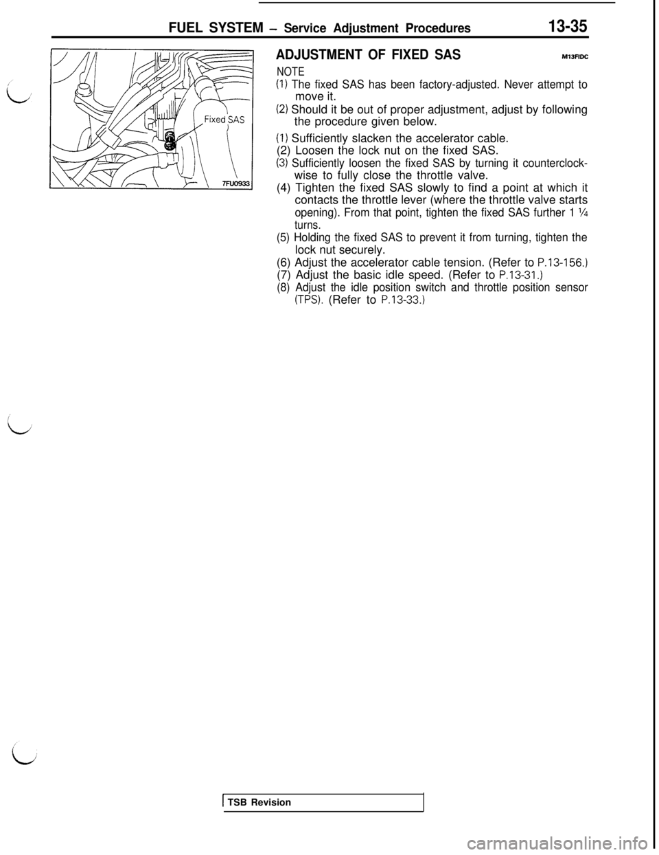
ADJUSTMENT OF FIXED SASMlJFlDC
NOTE
(1) The fixed SAS has been factory-adjusted. Never attempt tomove it.
(2) Should it be out of proper adjustment, adjust by following
the procedure given below.(I) Sufficiently slacken the accelerator cable.
(2) Loosen the lock nut on the fixed SAS.
(3) Sufficiently loosen the fixed SAS by turning it counterclock-wise to fully close the throttle valve.
(4) Tighten the fixed SAS slowly to find a point at which it
contacts the throttle lever (where the throttle valve starts
opening). From that point, tighten the fixed SAS further 1 l/4
turns.
(5) Holding the fixed SAS to prevent it from turning, tighten thelock nut securely.
(6) Adjust the accelerator cable tension. (Refer to
P.13-156.)(7) Adjust the basic idle speed. (Refer to
P.13-31.)
(8) Adjust the idle position switch and throttle position sensor
(TPS). (Refer to P.13-33.)
1 TSB Revision
Page 142 of 1146
13-36FUEL SYSTEM - 0
n-vehicle Inspection of MPI Components
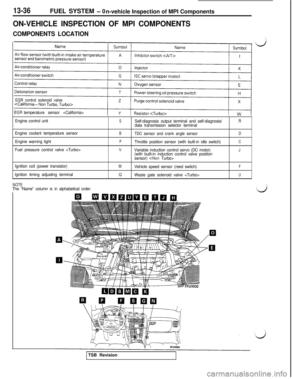
ON-VEHICLE INSPECTION OF MPI COMPONENTS
COMPONENTS LOCATION
EGR control solenoid valve
temperature sensor
Engine control unit
Engine coolant temperature sensor
Engine warning light
Fuel pressure control valve
Ignition coil (power transistor)
Ignition timing adjusting terminal
SSelf-diagnosis output terminal and self-diagnosis/Rdata transmission selector terminal
BTDC sensor and crank angle sensorD
PThrottle position sensor (with built-in idle switch)C
vVariable induction control servo (DC motor)J(with built-in induction control valve position
sensor)
MVehicle speed sensor (reed switch)F
QWaste gate solenoid valve U
NOTEThe “Name” column is in alphabetical order.TSB Revision
Page 143 of 1146
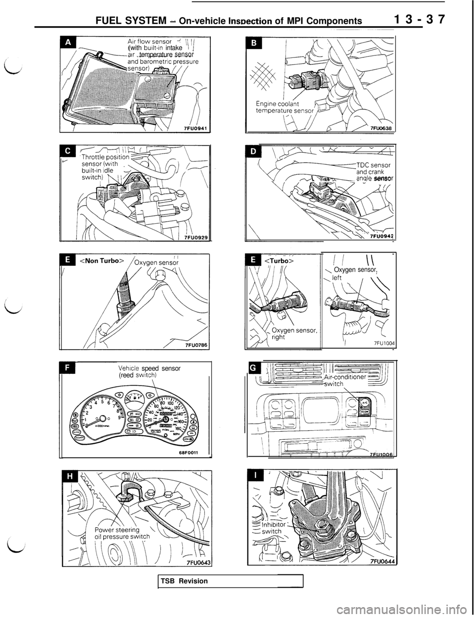
FUEL SYSTEM d On-vehicle lnwection of MPI Components13-37(with built-in intakeIair temperaturesensor
Vehicle speed sensor
(reed switch)J
wF~~::~:~~or- A.anale sensor
y\\ v 7Fbd942
ii \\\ Oxygensensor,
I7FU1004
//
\:/TSB Revision
Page 144 of 1146
13-38FUEL SYSTEM - Onaehicle Inspection of MPI Components
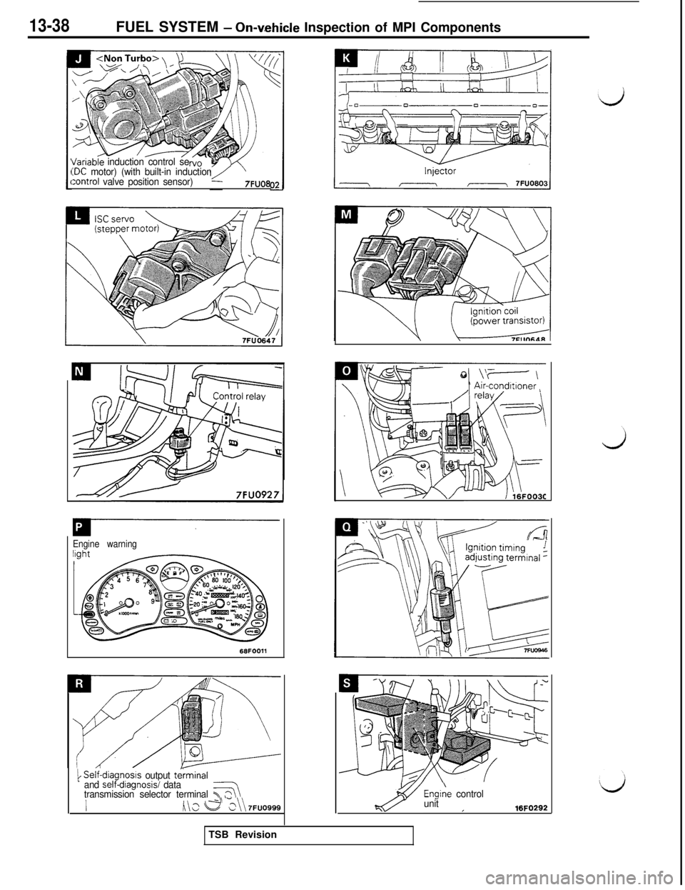
I/ariableinduction control se:DC motor) (with built-in induction:ontrol valve position sensor)7FUO8
Engine warning
1 Self-diagn,osls output terminal
and self-dlagnosisi data
transmission selector terminal T37
h\s e >\\ 7FUO999Engiie
control
unit
I16FO292TSB Revision
Page 145 of 1146
FUEL SYSTEM * On-vehicle Inspection of MPI Components
13-39
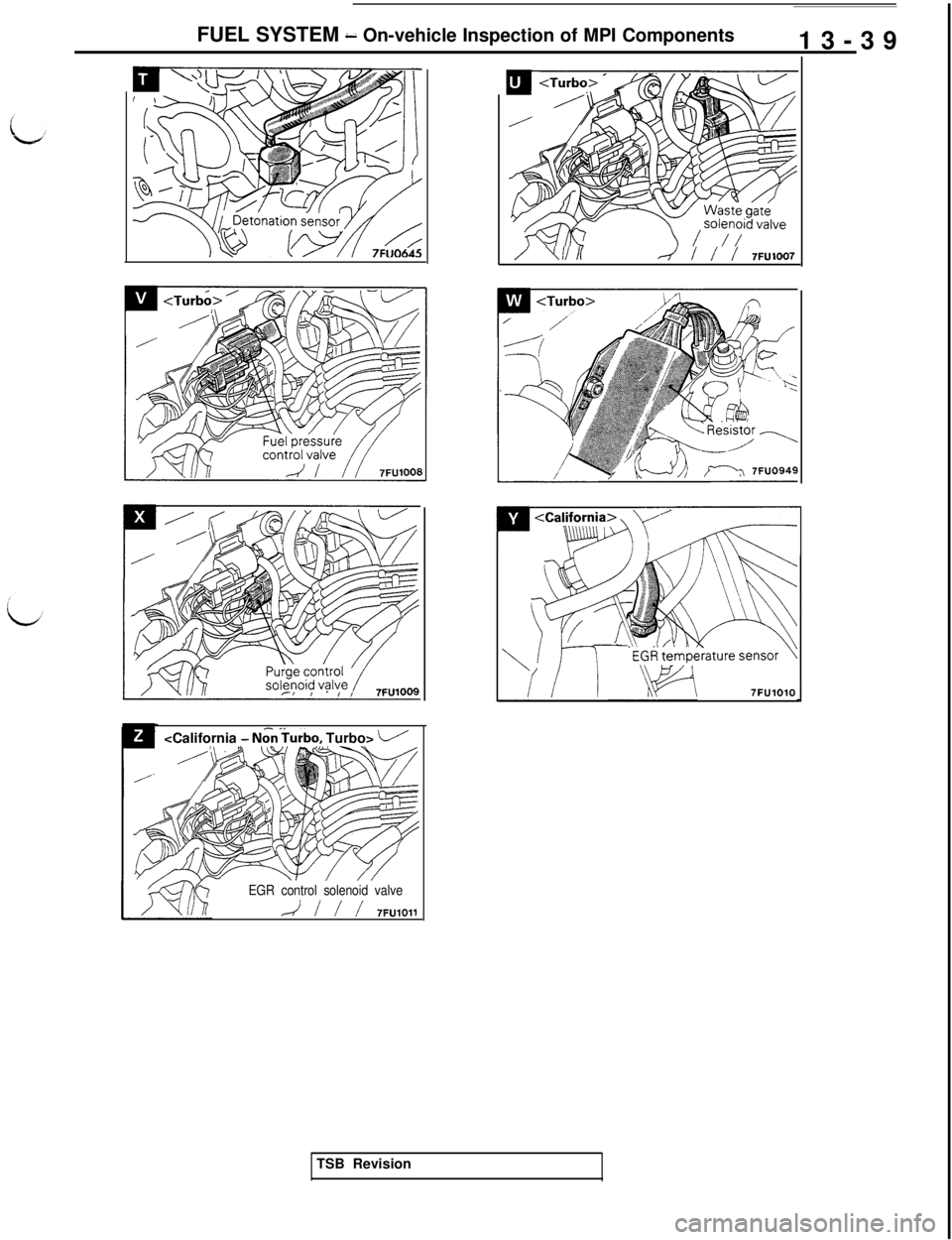
- N&Turbo, Turbo> i/
EGR control solenoid valve
A / / / 7FUlOll
/ Ylilr--/ / / / 7FU1007
7FUlOlOTSB Revision
Page 146 of 1146
13-40FUEL SYSTEM -On-vehicle Inspection of MPI Components
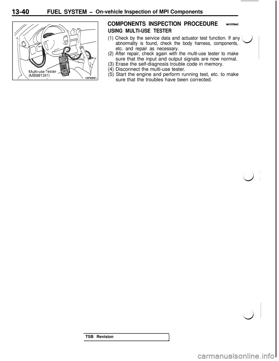
COMPONENTS INSPECTION PROCEDUREM13YBAC
USING MULTI-USE TESTER
(1) Check by the service data and actuator test function. If any ij
abnormality is found, check the body harness, components,
etc. and repair as necessary.
(2) After repair, check again with the multi-use tester to makesure that the input and output signals are now normal.
(3) Erase the self-diagnosis trouble code in memory.
(4) Disconnect the multi-use tester.
(5) Start the engine and perform running test, etc. to make
sure that the troubles have been corrected.
TSB Revision
Page 147 of 1146
FUEL SYSTEM - On-vehicle Inspection of MPI Components13-41
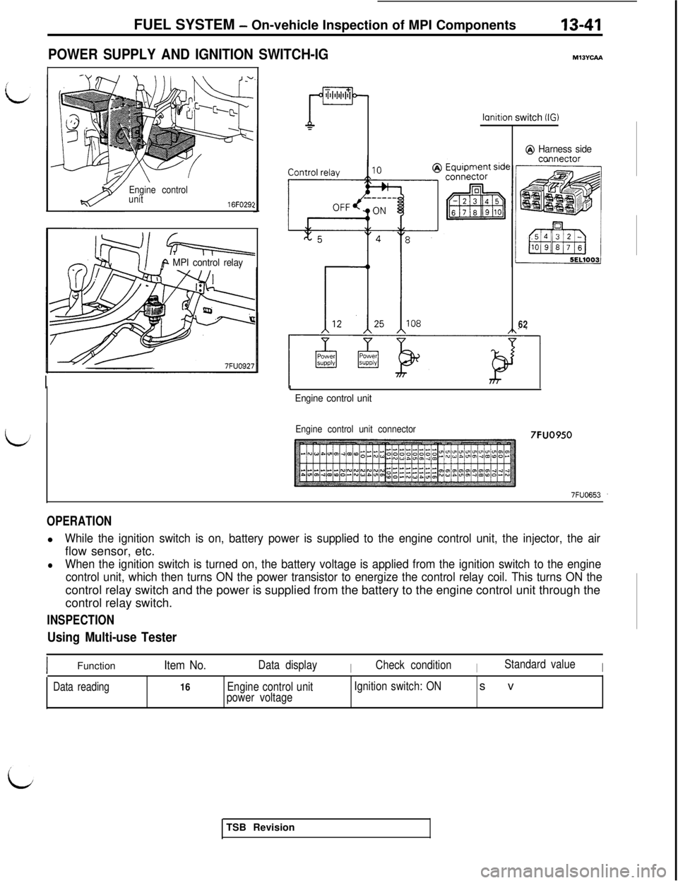
POWER SUPPLY AND IGNITION SWITCH-IG
Engine control
unit
16FO29:
Q-i=++=
iA MPI control relay
ml3Yuu
lcmition switch (IG)
@ Harness sideccmnector
62
I
Engine control unit
Engine control unit connector7FUO950
OPERATIONl
While the ignition switch is on, battery power is supplied to the engine control unit, the injector, the airflow sensor, etc.
lWhen the ignition switch is turned on, the battery voltage is applied from the ignition switch to the engine
control unit, which then turns ON the power transistor to energize the control relay coil. This turns ON thecontrol relay switch and the power is supplied from the battery to the engine control unit through the
control relay switch.
INSPECTION
Using Multi-use Tester
IFunctionItem No.Data displayICheck conditionIStandard valueI
Data reading16Engine control unit
power voltageIgnition switch: ONsv
TSB Revision
Page 148 of 1146
IS-42FUEL SYSTEM - On-vehicle Inspection of MPI Components
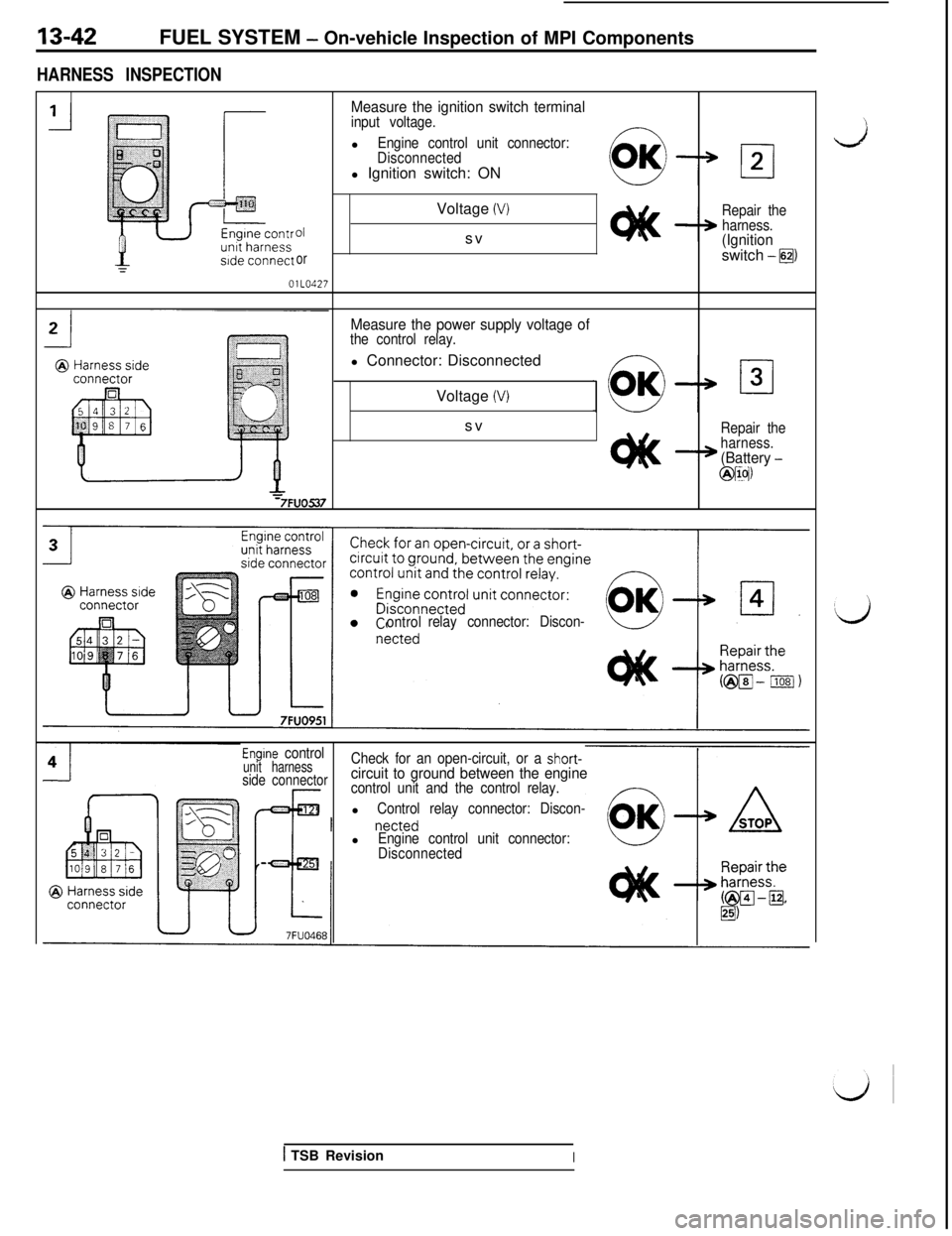
HARNESS INSPECTION
Measure the ignition switch terminalinput voltage.l
Engine control unit connector:
Disconnectedl Ignition switch: ON
01
orOlLO427Voltage
(V)svRepair the
harness.
(Ignitionswitch -@I
Measure the power supply voltage ofthe control relay.l Connector: Disconnected
Voltage
(V)sv
Repair the
harness.
(Battery -
@IIN
ontrolrelay connector: Discon-
Engine controlunit harnessCheck for an open-circuit, or a short-
side connectorcircuit to ground between the enginecontrol unit and the control relay.l
Control relay connector: Discon-l
Engine control unit connector:
Disconnected
1 TSB RevisionI
Page 149 of 1146
FUEL SYSTEM - On-vehicle Inspection of MPI Components13-43OlLO521
01 LO220
011022:
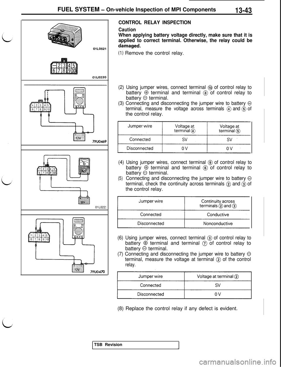
CONTROL RELAY INSPECTION
Caution
When applying battery voltage directly, make sure that it is
applied to correct terminal. Otherwise, the relay could be
damaged.
(1) Remove the control relay.
(2) Using jumper wires, connect terminal @ of control relay tobattery
0 terminal and terminal @ of control relay to
battery
0 terminal.
(3) Connecting and disconnecting the jumper wire to battery 0
terminal, measure the voltage across terminals @ and @ ofthe control relay.
(4) Using jumper wires, connect terminal @ of control relay tobattery
0 terminal and terminal @ of control relay to
battery
0 terminal.
(5)Connecting and disconnecting the jumper wire to battery 0
terminal, check the continuity across terminals @ and @ ofthe control relay.
(6) Using jumper wires, connect terminal @ of control relay tobattery
0 terminal and terminal @ of control relay to
battery
0 terminal.
(7) Connecting and disconnecting the jumper wire to battery 0
terminal, measure the voltage at terminal @ of the control
relay.(8) Replace the control relay if any defect is evident.
TSB Revision
Page 150 of 1146
13-44FUEL SYSTEM - On-vehicle Inspection of MPI Components
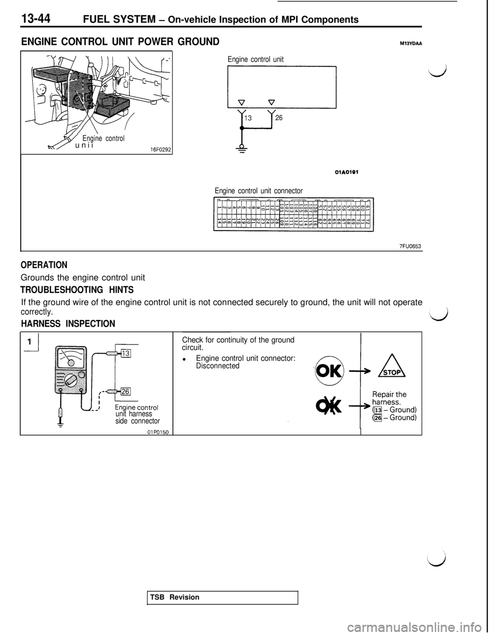
ENGINE CONTROL UNIT POWER GROUNDMlBYD~
wEngine controld/ unii16FO292
Engine control unit
L-7-l d
1326
Yx
01A01@1
Engine control unit connector
7FUO653
OPERATIONGrounds the engine control unit
TROUBLESHOOTING HINTSIf the ground wire of the engine control unit is not connected securely to ground, the unit will not operate
correctly.
HARNESS INSPECTION
unit harness
side connector
Check for continuity of the ground
circuit.l
Engine control unit connector:DisconnectedTSB Revision
Trending: diagnostic menu, length, oil reset, spark plugs, reset, clock setting, seat adjustment
